-
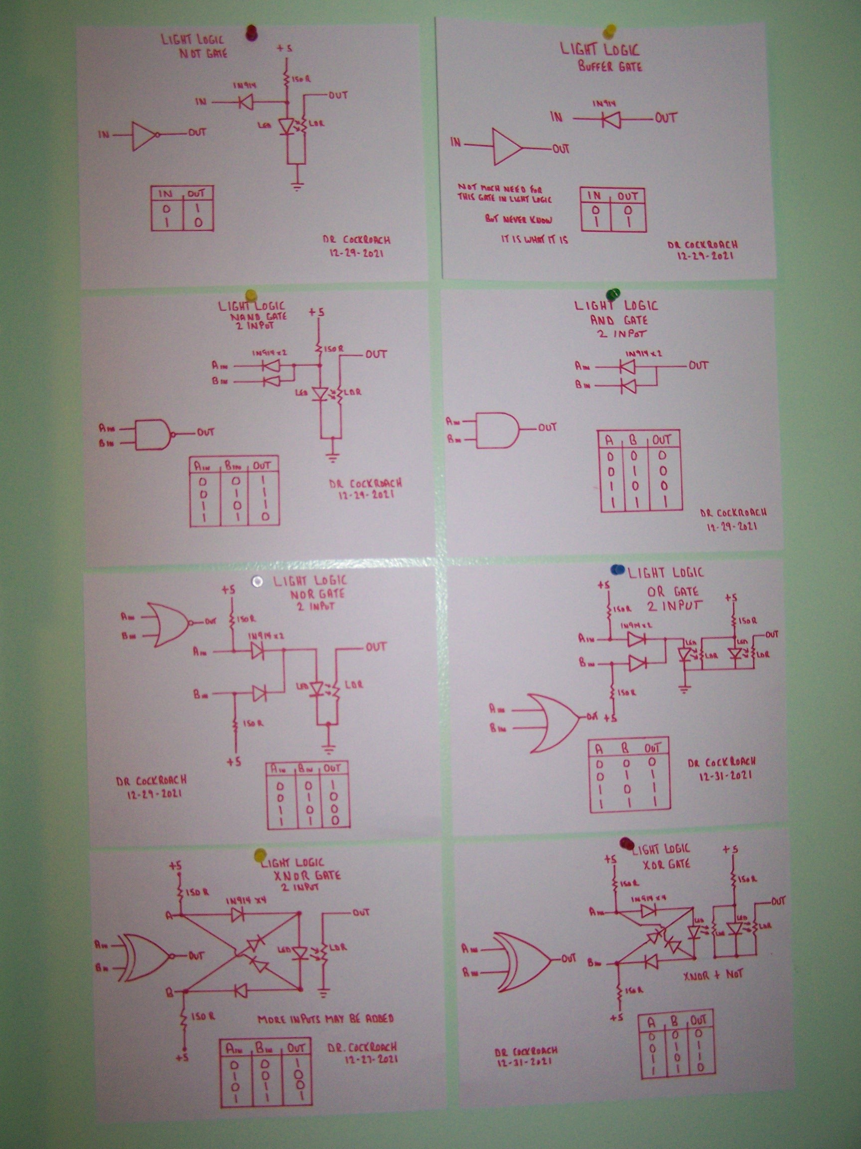
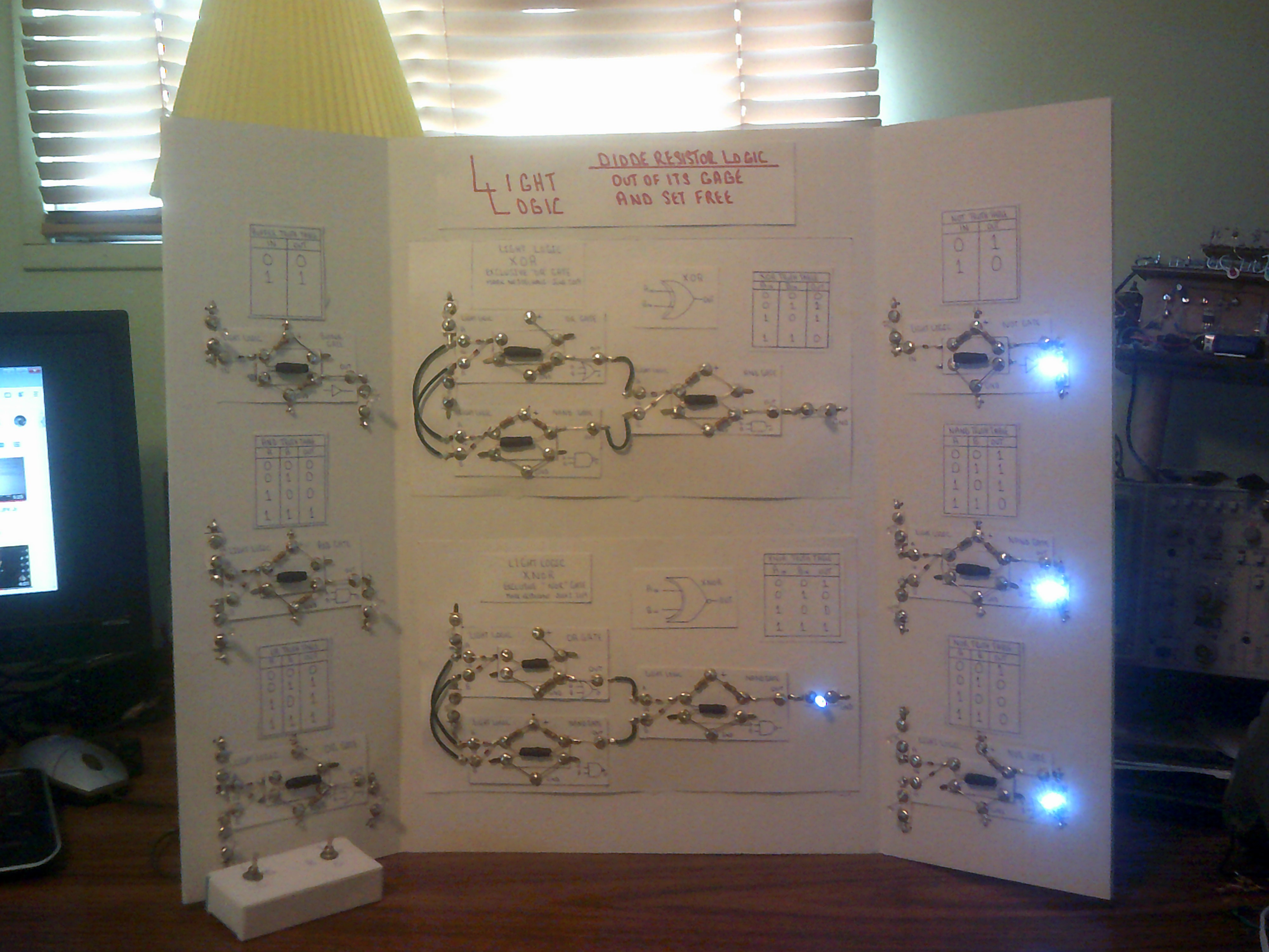
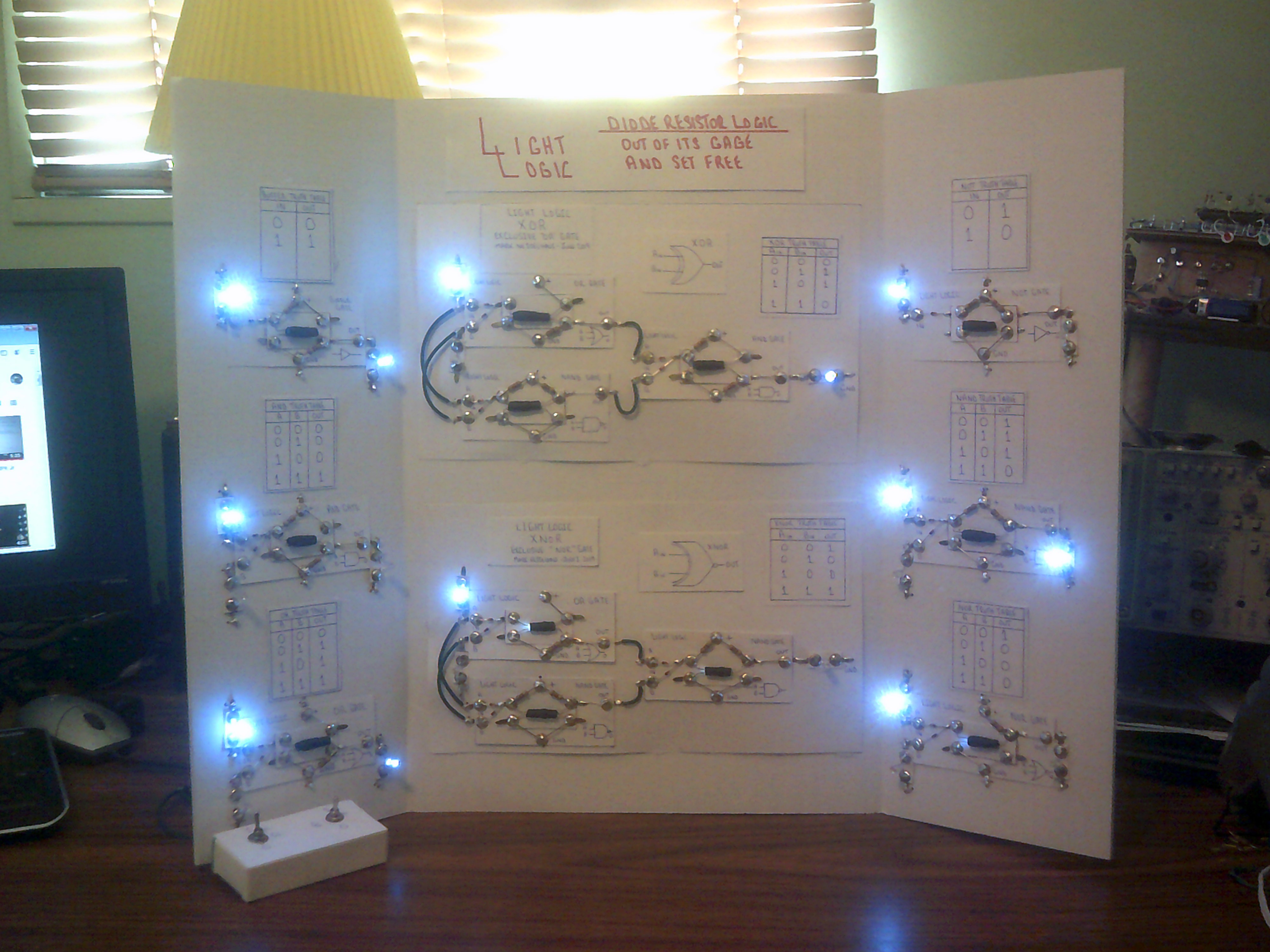
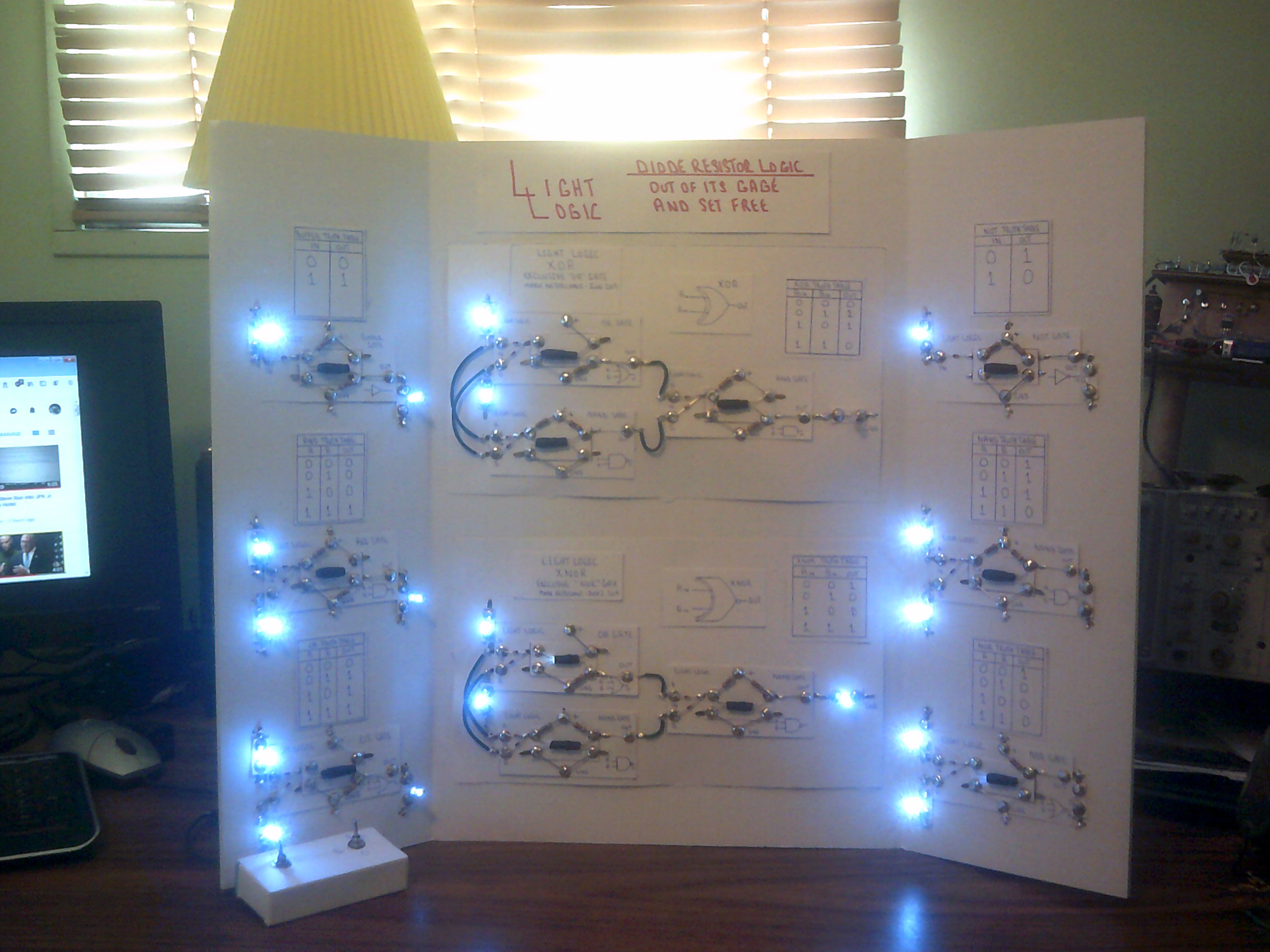
End of 2021 final Light Logic circuits
12/31/2021 at 23:55 • 0 commentsDecember 31, 2021
Not earth shattering but here are the final circuits for Light Logic. Happy New Year to everyone.
-
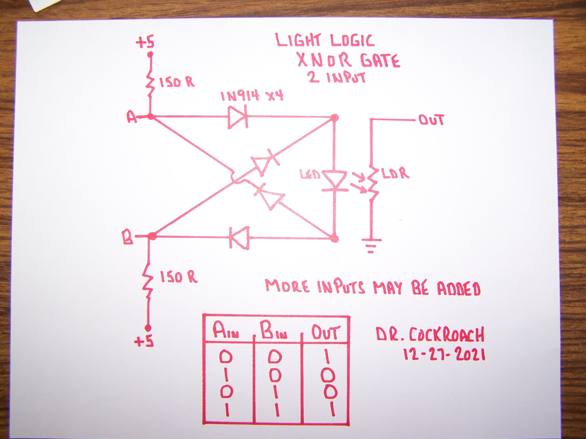
Improved XNOR gate
12/28/2021 at 14:10 • 2 commentsDecember 28, 2021 - After a bit of an absence I started improving on some of my Light Logic gate circuits. I was never satisfied with how my XNOR gate turned out so I ended up having a dream last night and when I woke up this morning I got to working on what I had dreamed about. The simple change is that I now feed 5 volts to the inputs continuously through a pair of 150R resistors. If there is no input at either A or B then the input is considered HIGH. If either A or B is grounded through a previous gate then the input is LOW. The Out of the LDR can be followed by a Light Logic Inverter gate to create a XOR gate or wired to any other gate as needed. I have this circuit on a bread board and it is working as it should. Remember, with Light Logic the output MUST be through the LDR to ground to be a counted as a solid Zero / Low. Anything else is counted as a One / High
-
Sequencer meets display
08/30/2019 at 00:32 • 0 commentsThis a great example of what diodes can do. The sequencer is just diodes, resistors and caps. The display and matrix from the IO project uses diodes only.
-
A Sequencer - The Next Addition
08/20/2019 at 18:58 • 0 commentsI might as well add my seven step sequencer to the demo panel. This sequencer will find its way into my processor build this winter using only Light Logic circuits.
-
Adding more to the Educational Demo Panel
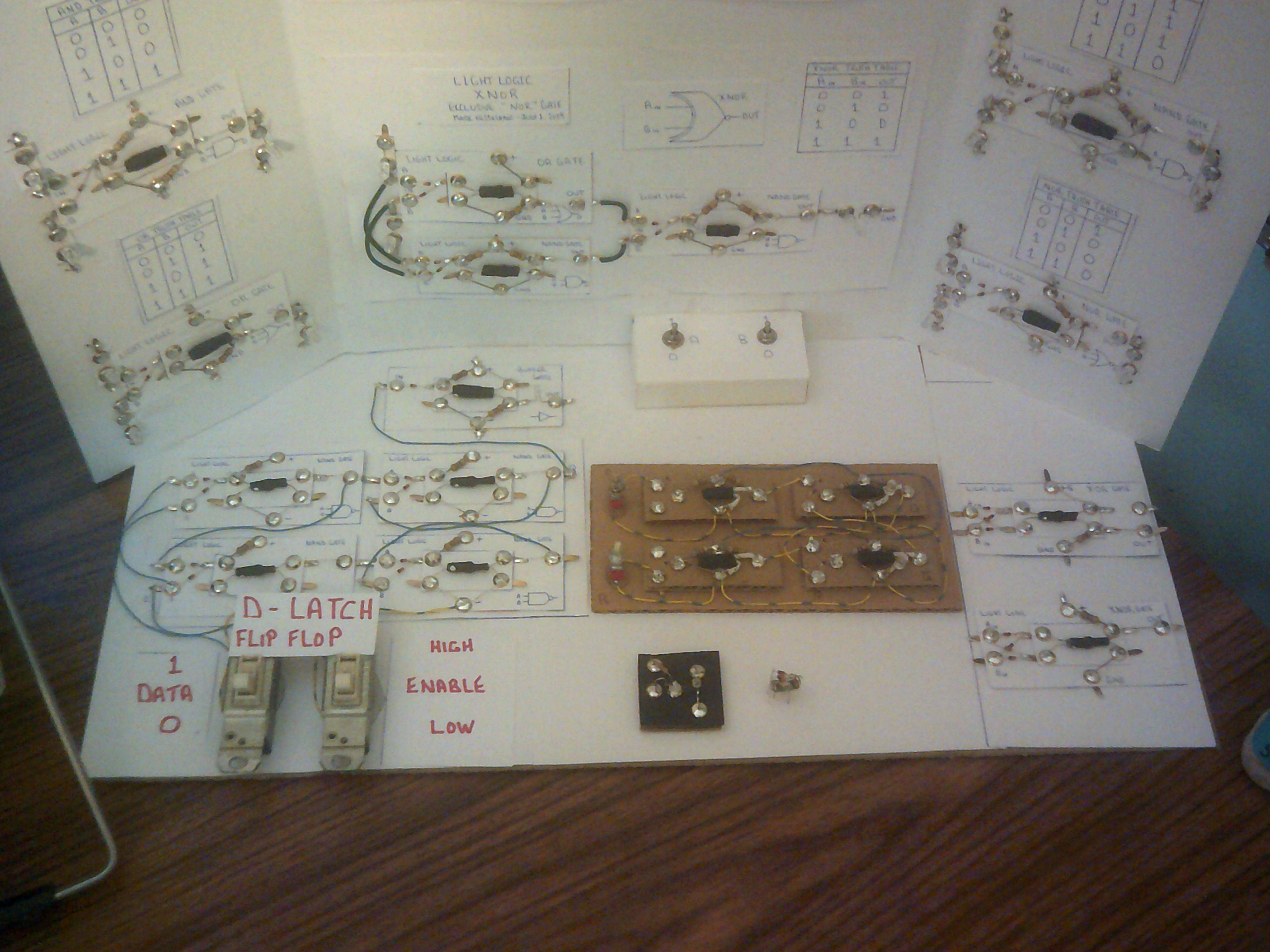
07/18/2019 at 23:31 • 0 commentsI am planning to add other Light Logic circuits to the panel in order to showcase the progress of developing these logic circuits. I will add the original S-R Latch, a gate using a 0402 SMD Led, my smallest 3 input NAND gate constructed and of course the new XOR and XNOR single gate modules. There will be more to come.
-
A D-Latch added
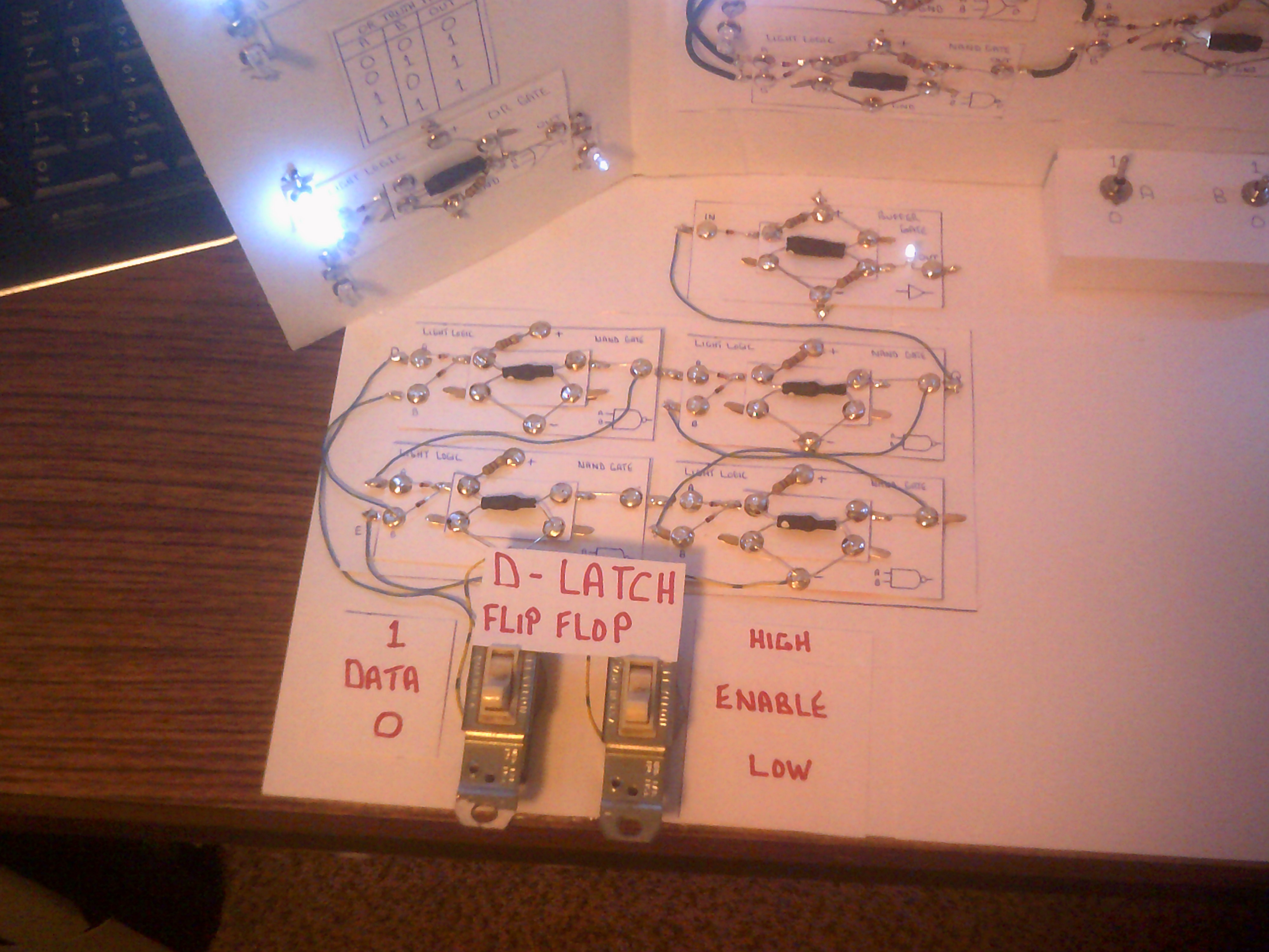
07/14/2019 at 17:32 • 0 commentsThe demo panel now sports a working D-Latch flip-flop that includes a led driver in the form of a Buffer gate on the Q output. You might notice that the NAND gates have had their CdS voltage supply resistors removed. These NAND gates as wired do not need a voltage to indicate a ONE output. Indeed the output can be a floating 0 volts and still count as a ONE unless the following gate is either a OR or NOR gate. It is the ground connection that makes a firm ZERO output do the job. That is why I am using a Buffer for the output Led indicator.
-
The truth of Light Logic
07/04/2019 at 15:31 • 0 commentsHere are the four stages of Light Logic gate operation.
Switch setting 0,0
Switch setting 0,1
Switch setting 1,0
Switch setting 1,1
 Dr. Cockroach