 kodera2t
Now let's start measurement. One important point before measurement is,
We should NOT connect adaptor before calibration finishing!
In the software named "scopy" by Analog Devices, initially it will recognize USB connection to the computer and click "connect" and the button will turn to "calibrating". Still we should not connect anything,
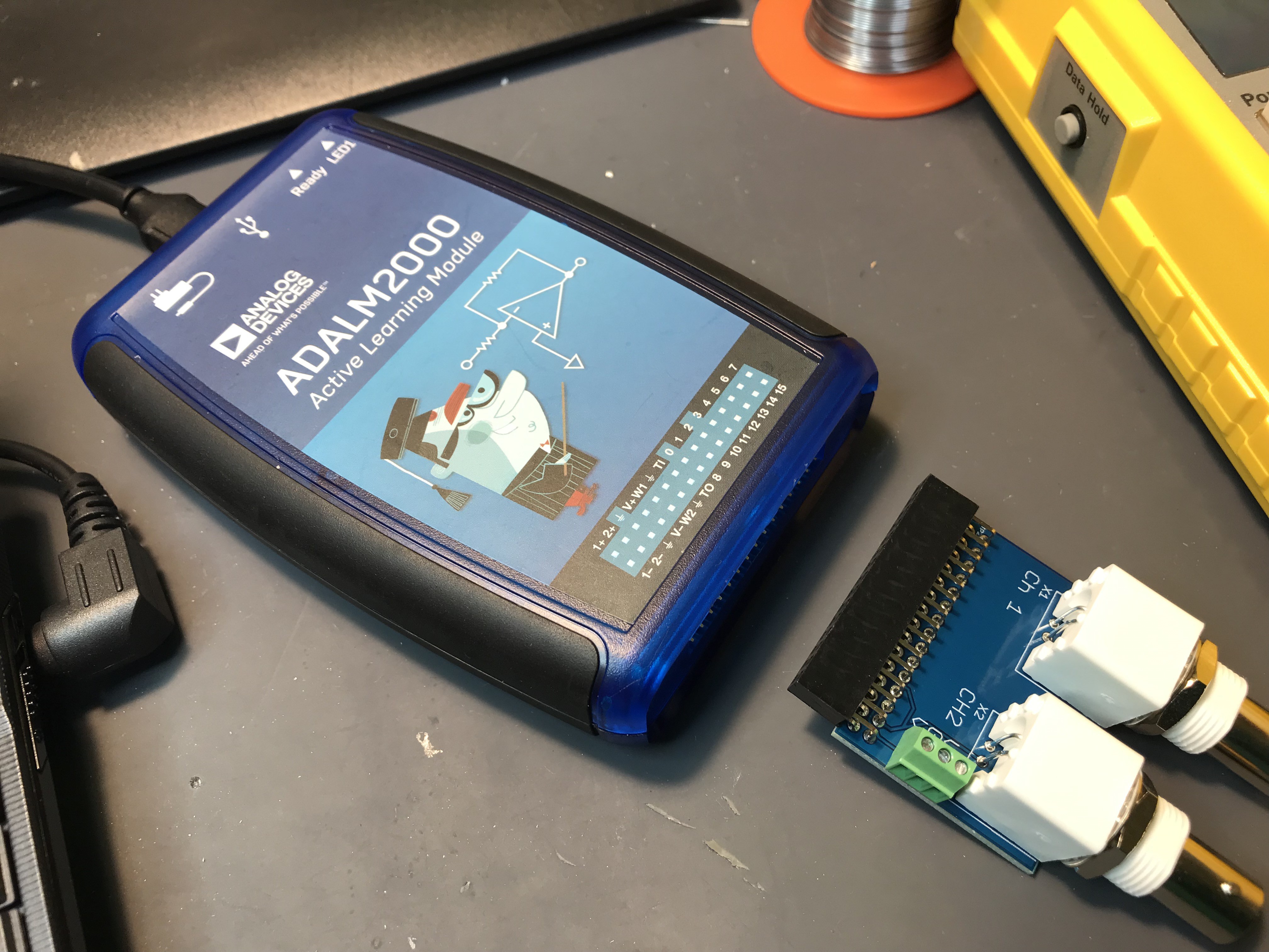
and when the button turns to "disconnect", we can connect adaptor to ADALM2000 as below.
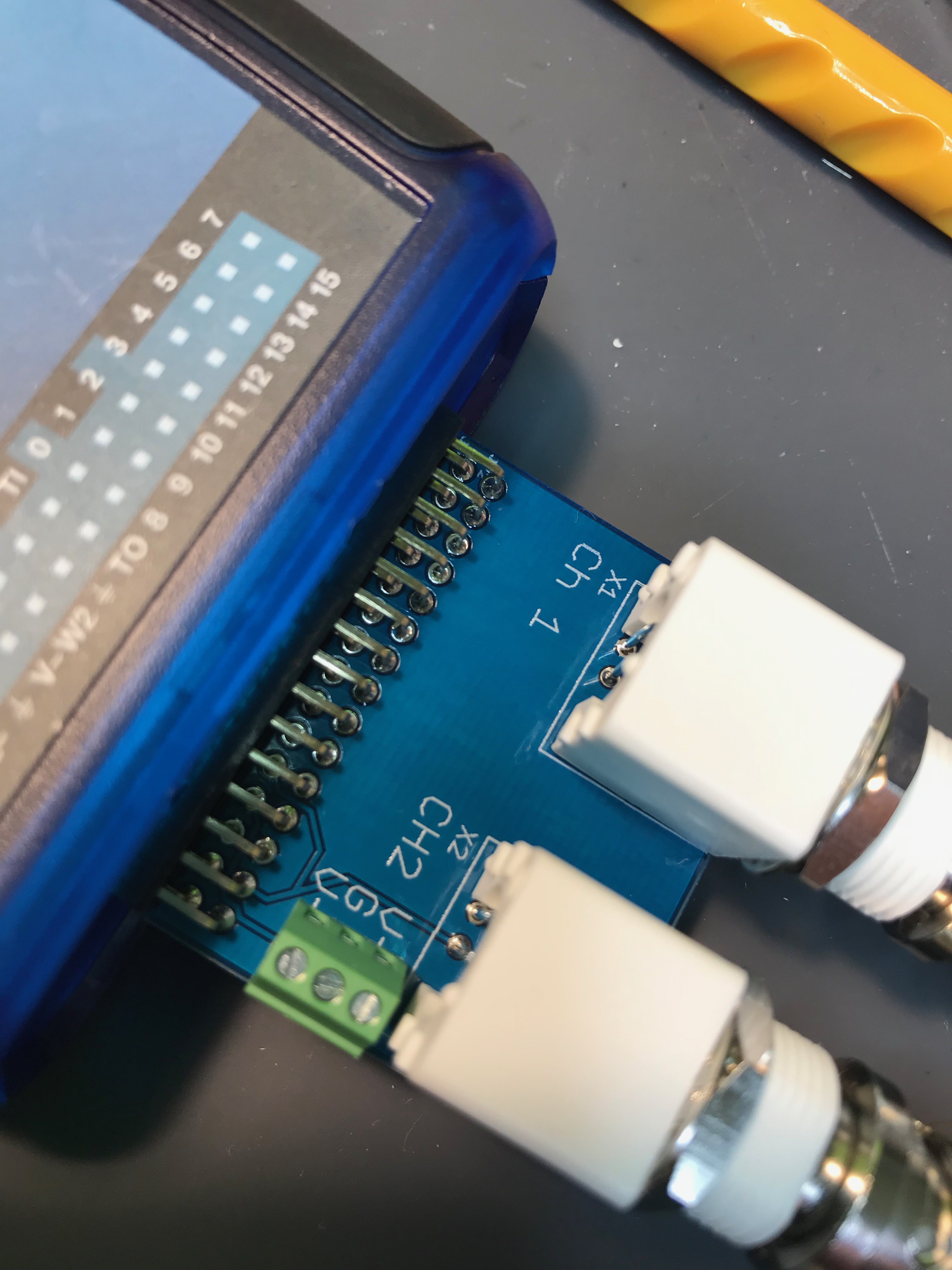
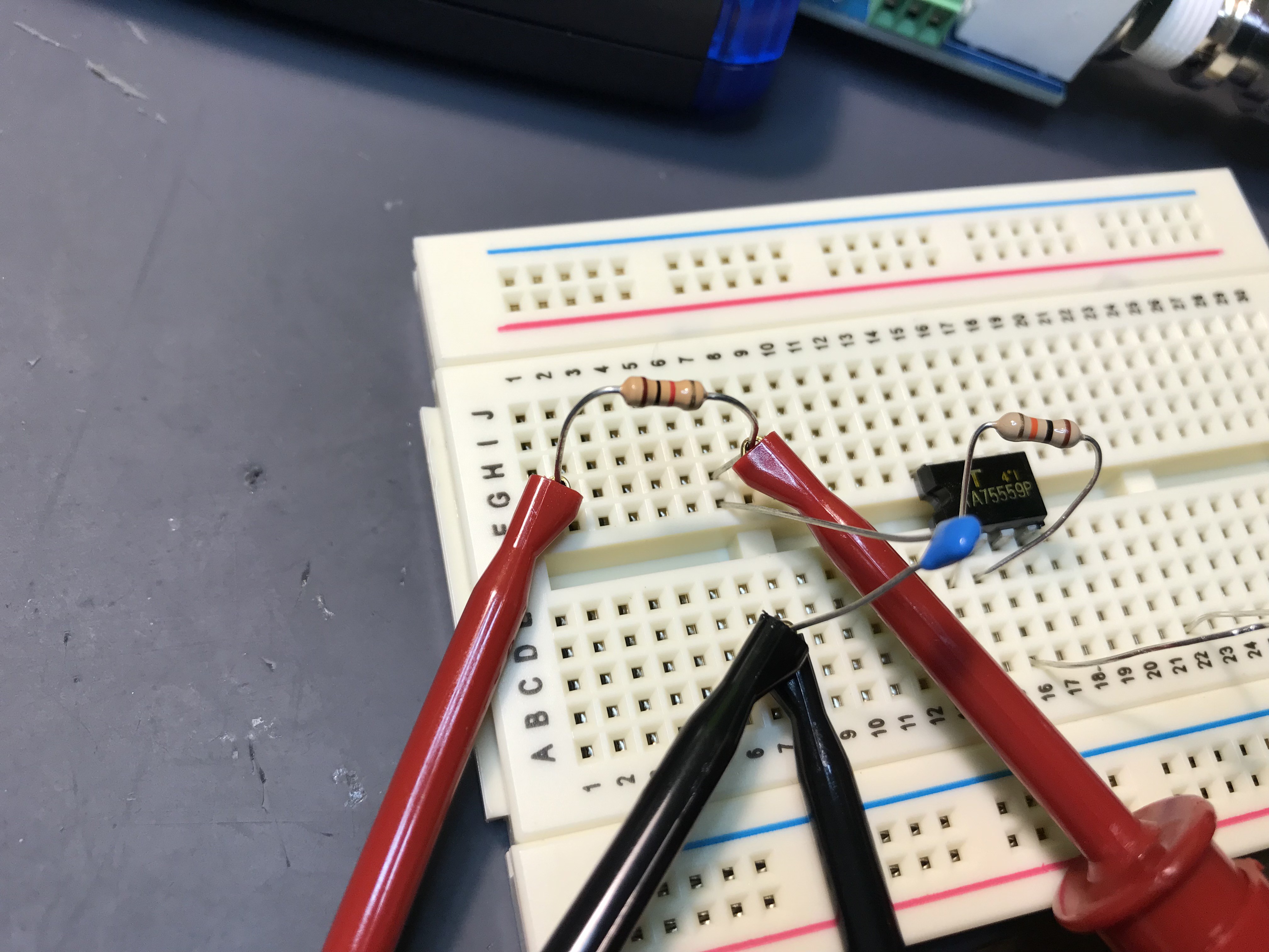
The board as Ch1, Ch2, and green terminal for the embedded power supply. Now let' make a simple connection of RC circuit (In my case, 1k and 0.1 uF). Red clip are in/out of DUT and black ones are GND.
Now let's go to Scopy. Indeed, all of available network analyzers are automatic for parameter setting, but NWA (network analyzer) of ADALM2000 is "full manual". All of parameter should be cared to get proper result.
We have to set
(1) Start, stop, step of frequency (as same as VNA).
(2) Measurement signal level. If it is too small, S/N of the measurement will get worse, and if too large, some active DUT device will saturate and wrong response will be shown.
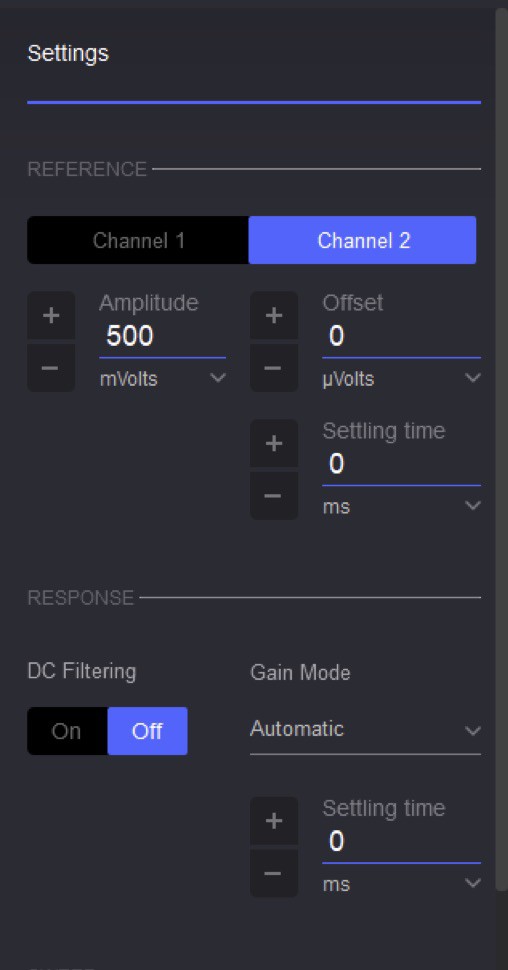
(3) If you will use my adaptor, please set "REFERENCE" to "Channel 2" as above.
If 1k/1uF LPF is measured with range from 100 Hz to 100 kHz, you will get the response as above by clicking "single".
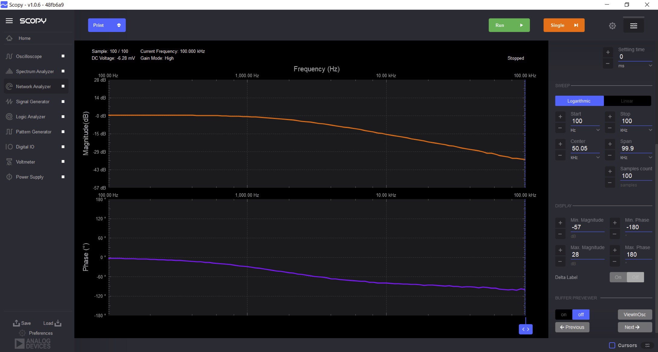
This circuit is not dynamic one and we don't need continuous measurement but if you prefer refreshing result, just click green "Run" button.
Discussions
Become a Hackaday.io Member
Create an account to leave a comment. Already have an account? Log In.