Kyle Isom
I couldn't sleep one night because I got it in my head to build this. The original journal entry can be found here.
The goal is to start really simple, and to build everything on top of ROS.
Kyle's robotics experimentation platform.
Already have an account? Log in.
To make the experience fit your profile, pick a username and tell us what interests you.
I couldn't sleep one night because I got it in my head to build this. The original journal entry can be found here.
The goal is to start really simple, and to build everything on top of ROS.
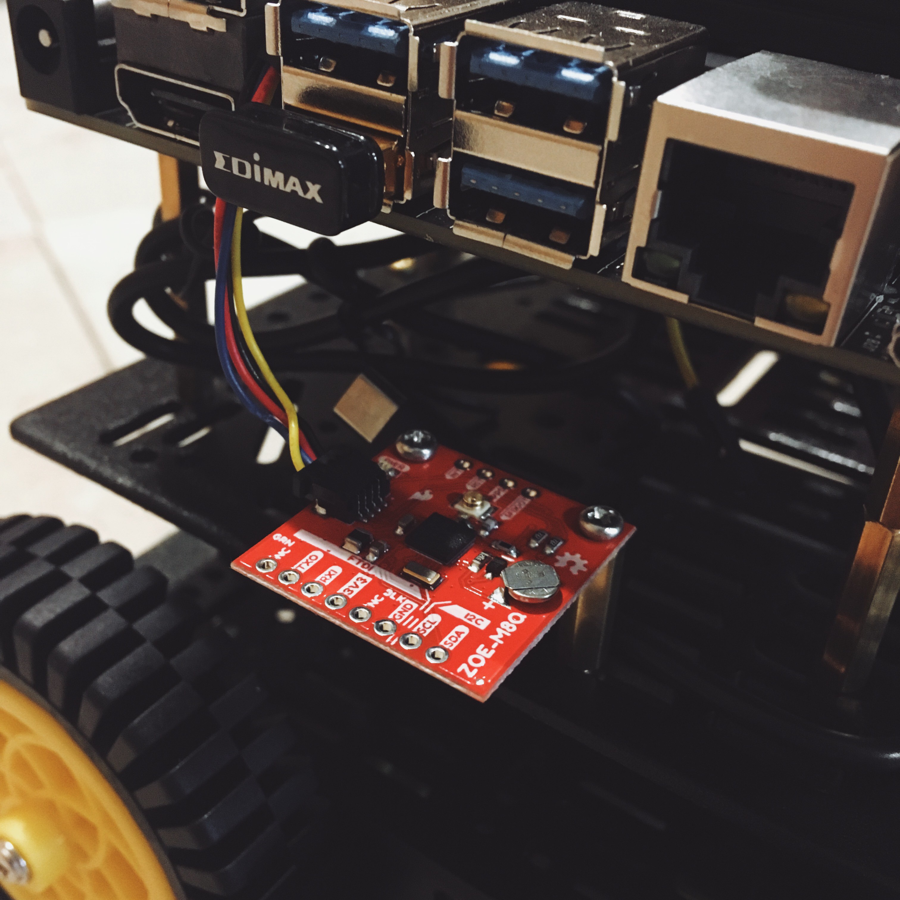
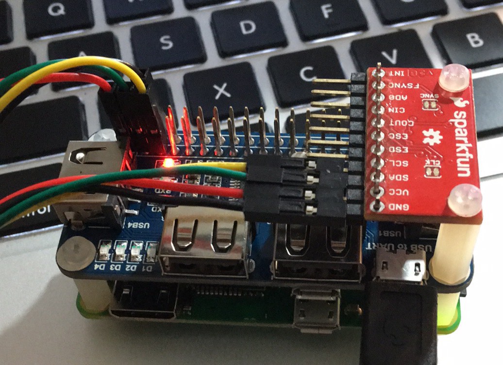
Wired up a ZOE-M8Q GPS that communicates over I2C. I picked it up during a SparkFun sale, and figured I should do something with it.
All right, I've got a direct-control drivetrain test work; the ROS node part works too. The next step is to write a general motion control cognitive process to start integrating motor control with sensor input.
For example, the motion control cognitive process needs to continually estimate its motion; if the motors are supposed to going and the robot isn't moving, the motors are stalled and will pull too much current - even at 3.3V, this will cause a lockup.
Here's a video:
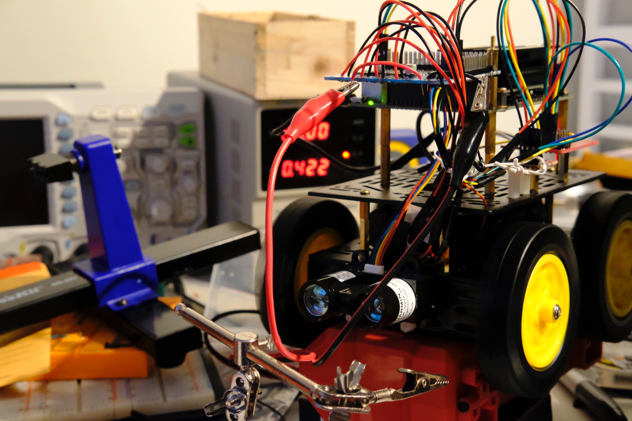
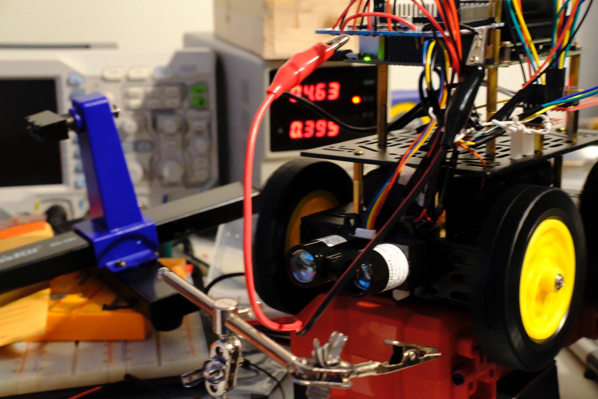
I did some experiments hooking up the motor controller to a bench power supply. Here's the motors running on full speed with a 5V, 1A current limit (they're running at about 422mA).
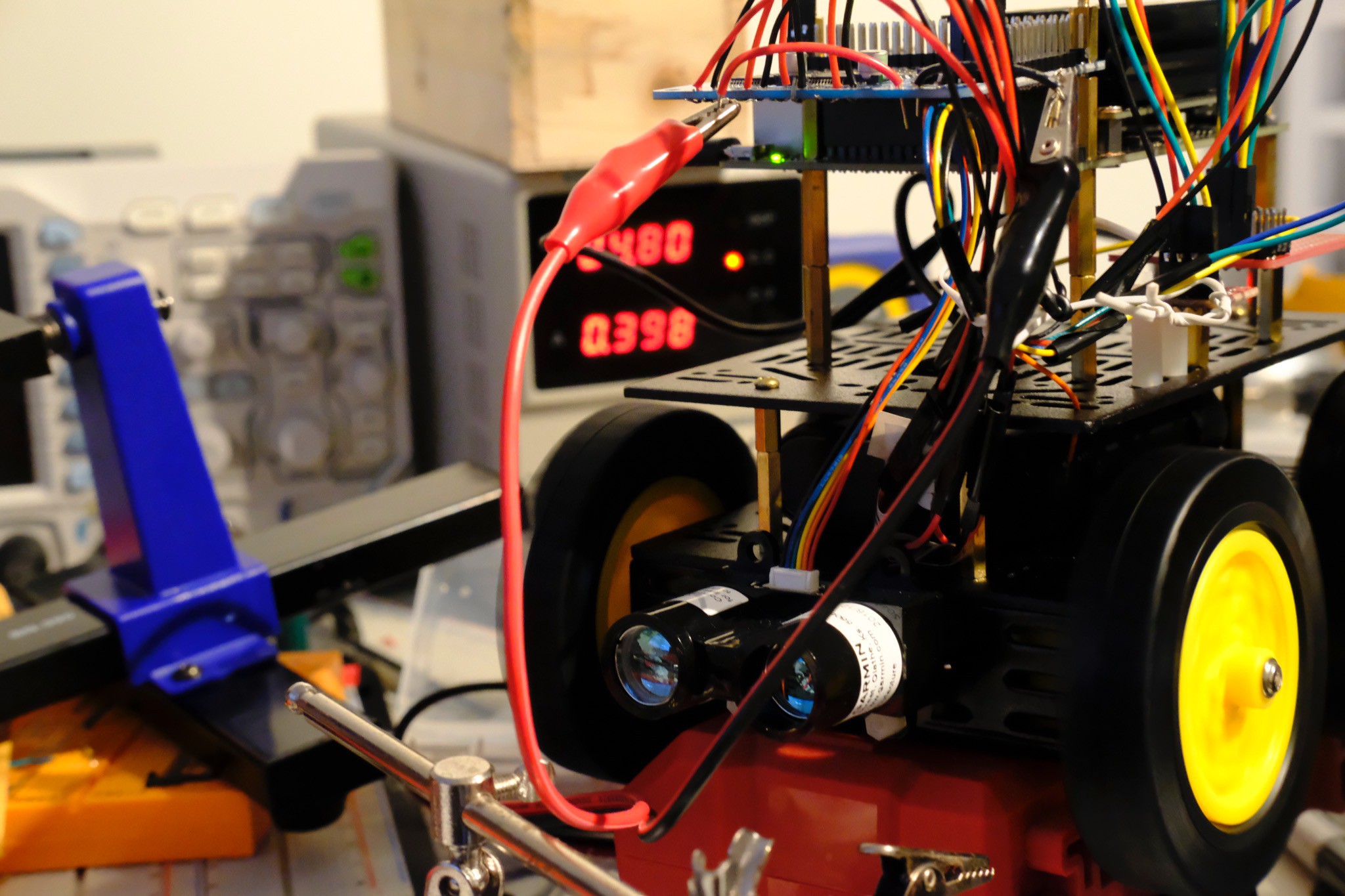
I experimented with current limiting: a limit of about 398mA causes the voltage to fluctuate between about 4.7 and 4.8V.
Since the Jetson isn't connected to this, the power supply doesn't cut out - which means the motors just get a lower voltage, and they're okay with that.
I had a "genius" idea; I could connect the motor power supply to the 3.3V rail instead of the 5V rail to act as a current limiter. It sort of works, as long as it's not on carpet... there's just too much friction, I guess. It'll at least buy me some time while I figure out a better power solution.
I wrote a quick C++ program (src/krex/src/util/powermon.cc) to dump the current, power, voltage, and temperature every millisecond; I found that when I was saving to file on the SD card, the immediate power off would cause me to lose data. So, I used nc(1) to pipe the data to my laptop, and it was revealing.
Each line in the log file is a comma-separate list of values; for example, a representative baseline with nothing running is
240,1205,5024,34000
That's 240mA of current, 1.205W, 5.024V, and 34ºC.
Let's take a look at what happens when I initiate a driving action:
432,2132,4936,34500
432,2132,4936,34000
432,2132,4936,34000
432,2132,4936,34500
432,2132,4936,34000
432,2132,4936,34000
432,2132,4936,34000
432,2132,4936,34000
424,2092,4936,34500
424,2092,4936,34500
424,2092,4936,34500
424,2092,4936,34500
424,2092,4936,34500
424,2092,4936,34000
424,2092,4936,34000
424,2092,4936,34500
424,2092,4936,34500
424,2092,4936,34500
424,2092,4936,34500
424,2092,4928,34500
432,2132,4936,34500
432,2132,4936,34000
432,2125,4920,34000
432,2111,4888,34000
440,2140,4864,34000
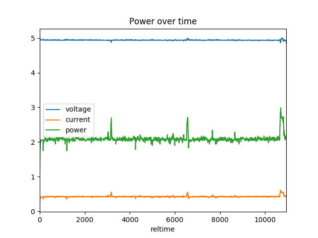
You can see the current usage stabilize around 430 mA with a power usage of 2.1W. The temperature remains about constant. The voltage, however, starts dropping:
You can see a current spike when the motors start, and that's when the voltage starts to drop. From Nvidia's docs:
The critical point is that the Jetson Nano module requires a minimum of 4.75V to operate.
The voltage drop from the current spike is pretty clearly causing the undervoltage. So, what can I do? Well, I think the easiest thing is to cut up a USB cable, providing output for both the motor hat and the Jetson. I could probably buffer voltage using a cap, too.
Not the most confidence-inspiring power setup :)
Honestly, what I need to do is to build out a battery pack for this. Maybe an 18650-based LiPo pack, I don't know. The USB power pack is both convenient and a real pain. Ideally, if I could get something the size of the PowerCore 10000 with a pair of USB ports, that would be nice. So power is going to be an issue for a bit until I can sort it out, and I'm backpacking next week, so nothing will get done. I can probably find some time tonight to wire up a battery pack to it though to at least verify my hypothesis about the issue.
Thankfully, these appear to be sorted out, except for the lidar. For that, I think I need to create a second class of I2C interface that has separate read and write file descriptors.
Once I set up the MPU9250 properly, the initialization problems went away and all seems well with it. Now I need to actually add an interface to the data from it, and support the AK8963 magnetometer.
I mirrored the current sources to Github, and I'll update it occasionally as I get things working.
I haven't completely sorted out the power issues; they seem to be somewhat mitigated by ramping up the motors (which I'm doing manually). I still get random shortages, though. I wonder if it's just drawing too much power, so I need to consider that. The datasheet mentions a max of 170mA max draw at 3V, and looking around on the internet makes it look like it's under 200mA. So, let's say 200mA per motor * 4 motors, which is 800mA. Now the motor hat is rated to provide 1.2A per motor with a max draw of 3A, so it seems like that's well within the design specs.
The other problem I'm facing is with the I2C bus. I can talk to the motor controller just fine, but I'm having issues talking to the IMU with what looks like a bus issue. Occasionally, there are arbitration issues on the bus, random NAKs, and the rest of the time it's a crapshoot whether the who am I register (which should return a fixed value) actually returns that value. I'm using the Linux i2c-dev library, which provides a file descriptor onto the bus. When it fails, I get one of two issues: "remote GPIO failed" or "resource temporarily unavailable." I haven't correlated the two yet to figure out which is the arbitration issue and which is the NAK.
The arbitration issues sound like competing masters. The IMU (an MPU-9250) has a master mode, so I should probably make sure that's disabled.
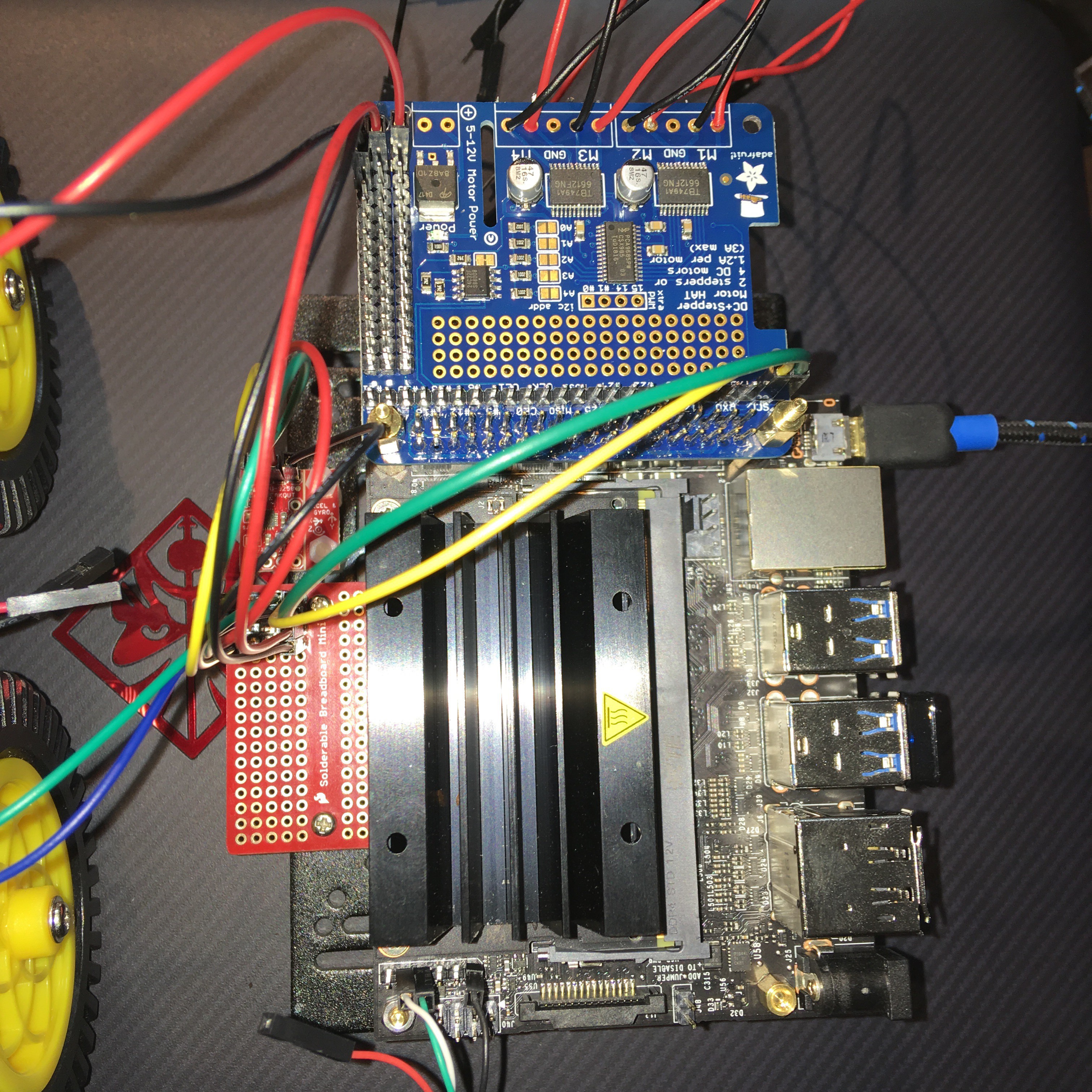
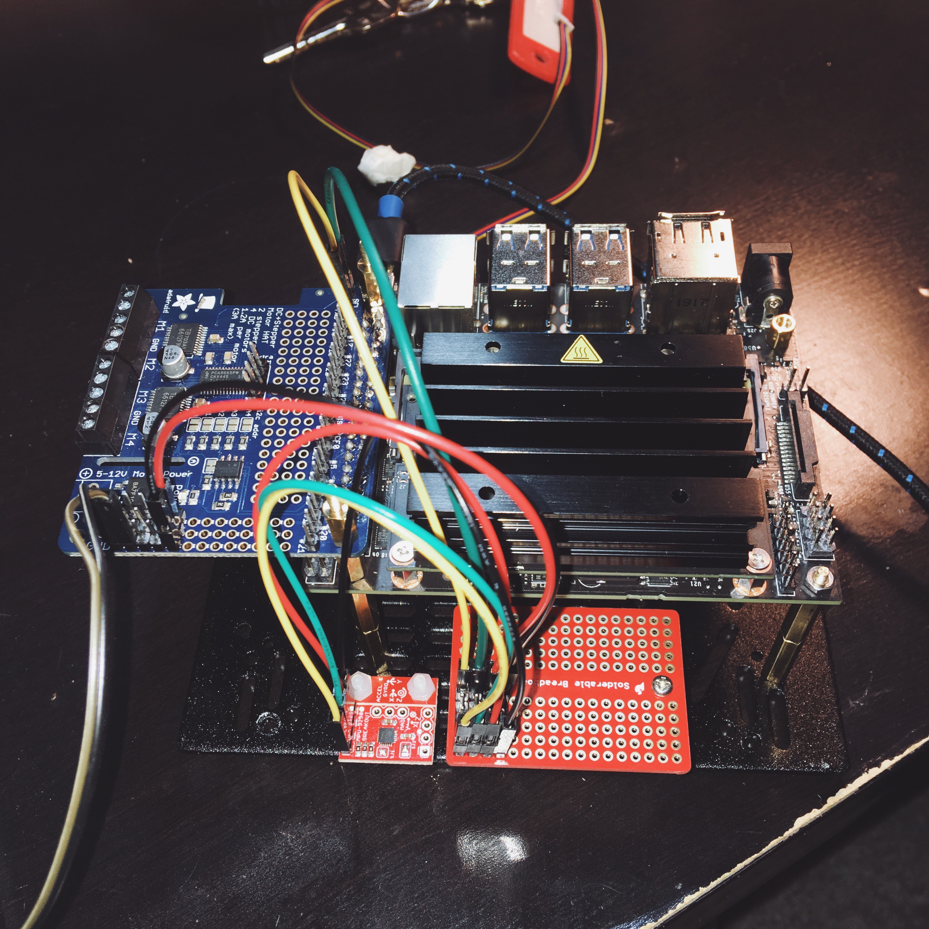
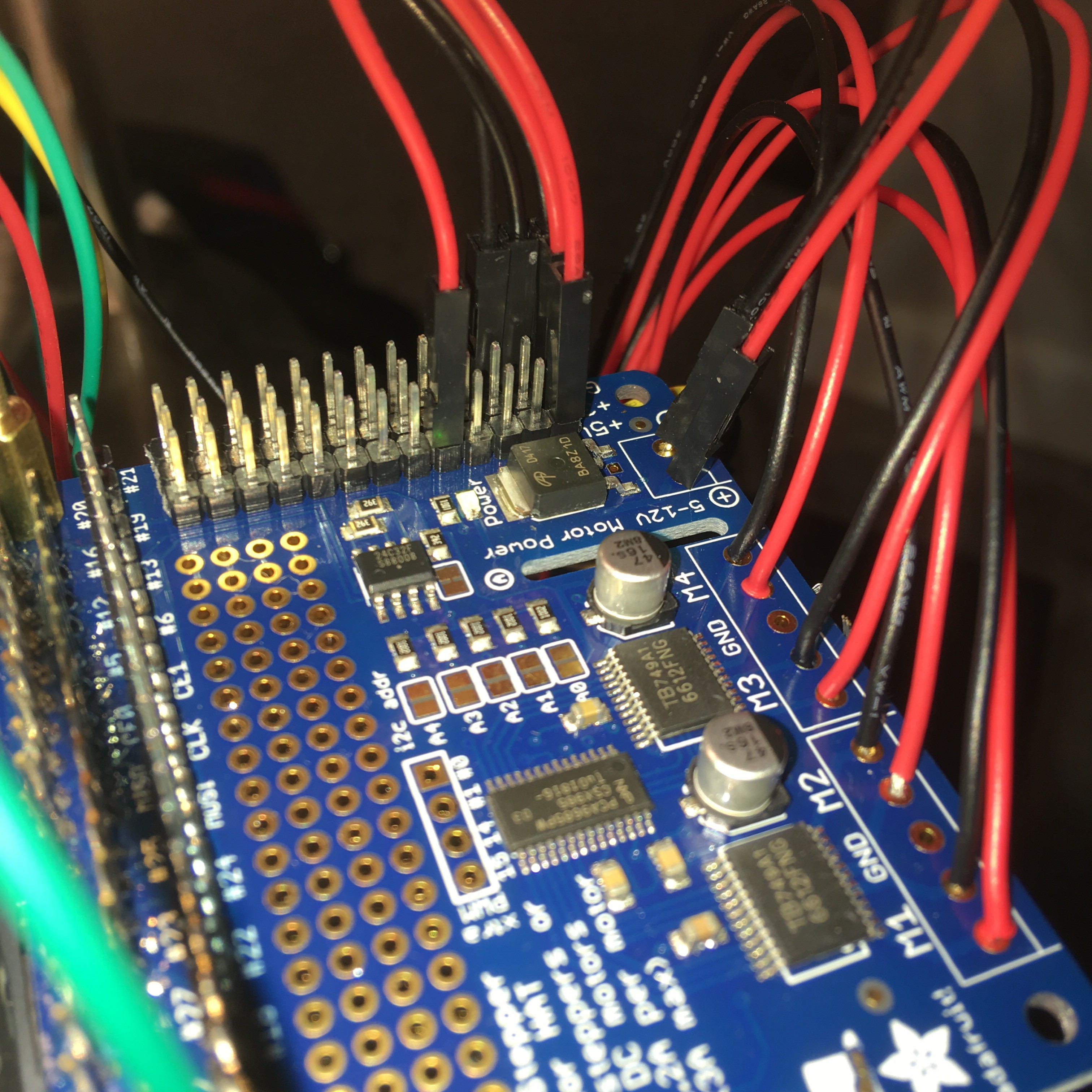
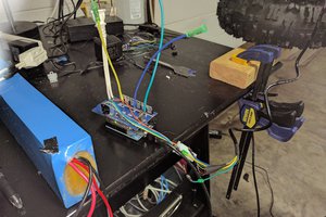
Hardware-wise, I basically have this:
jetson -> motorhat -> expander -> IMU
The expander is just a solderable breadboard that acts as a bus multiplexer: it lets me connect a bunch of things to the I2C bus. One row of pins is connected to the motor hat's I2C pins (which break out the I2C bus from the Jetson), ground, and a 3.3V connection. The IMU is a 3.3V device and it's definitely powered.
Both the motorhat and the IMU have pull-up resistors, so that's something else to consider.
So, the next steps to sort out the I2C problems are
And the next steps for debugging the power problems are
A few more tests and it looks like I'm running into power issues. I was dreading the prospect that my battery isn't up to par (2.4A @ 5V, with a 10Ah rating), but the issues happen with a wired connection, too.
What happens is that I kick power to the motors, and the whole thing shuts down. Well, I can still see the motor controller is powered, but the Jetson is dead in the water - even on serial console. The power light's out, so it's probably an overcurrent situation. I need to break out the multimeter when I have more time.
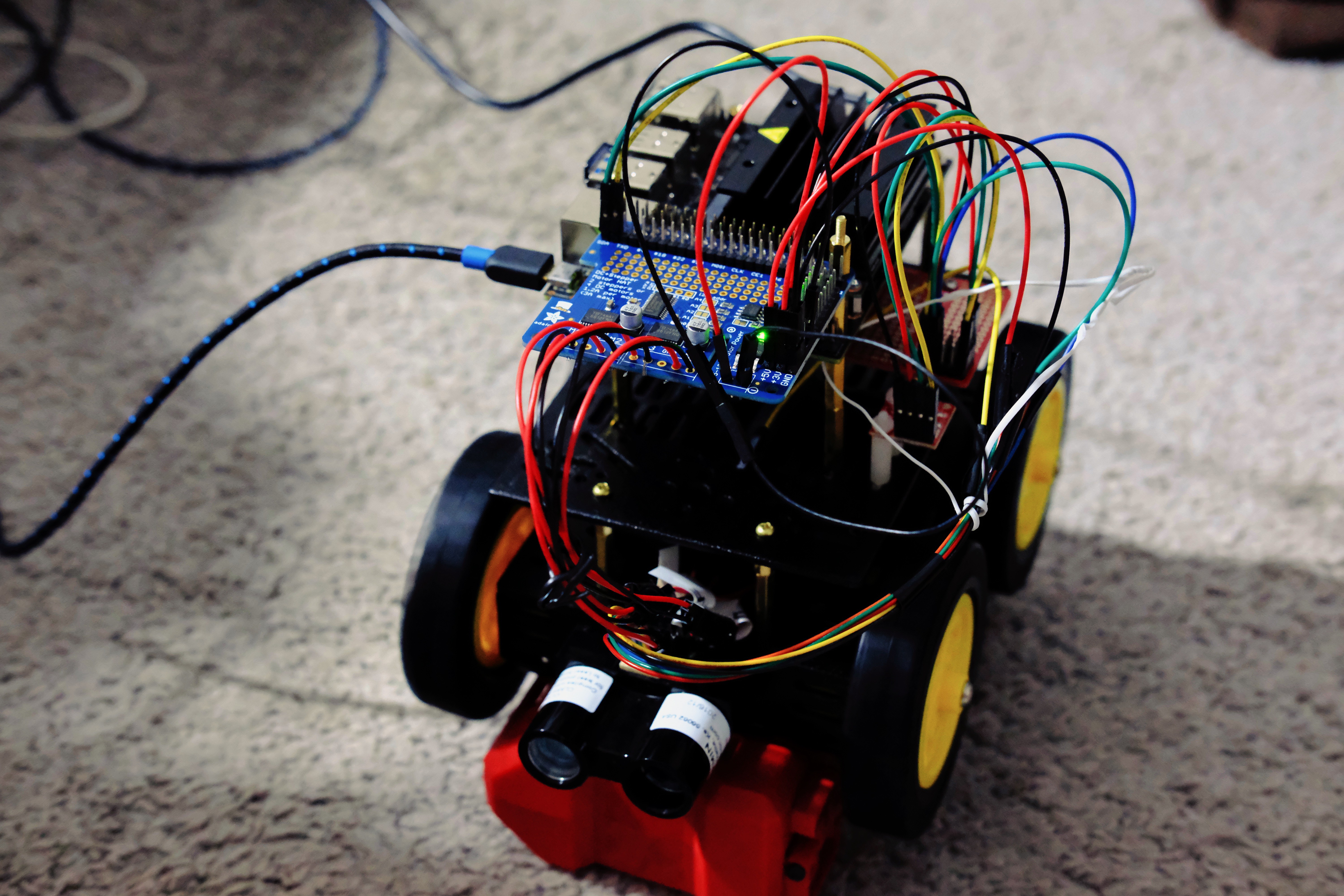
It moves!
I've got the motor controller working and sorted out a few misunderstandings with the PCA9685 (that's what I get for writing a bunch of code and not testing on the robot as I was building it... though that wasn't an option), and it drives. It even turns. It's basically hardware complete, though I'm still thinking about adding a camera to it.
I'm not too disappointed in the code I wrote, either (it's all C++). This validates a bunch of things:
Next up: getting the IMU working. I don't have to write an I2C library, and I don't have to process incoming messages - just read, calibrate, and so forth.
So I got the replacement motor controller and ended up soldering in jumper wires to the motor ports to simplify connecting the motors; I also did the same to the LIDAR-Lite harness. The Jetson still doesn’t want to see the lidar, but some minor googling indicates that this is due to the use of a repeated start by the I2C bus, so I need to investigate further.
The top plate is too big to take on the bus, and the first tasks are all low-level control tasks, so I put together a Pi Zero dev board to work on these. I’m writing most of these in C++ with a ROS interface, so while I don’t have ROS working on the Pi Zero, I can get the components working.
So, it turns out that the wheels being as close to the chassis as they are, and the footprints of my components, I either had to go with an awkward layout or find another top plate to stack. I decided to go with the latter, and it should be here Monday.For now, I’ve got the top plate set up like this.
 nerd.king
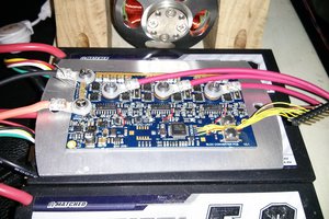
 Jarrod