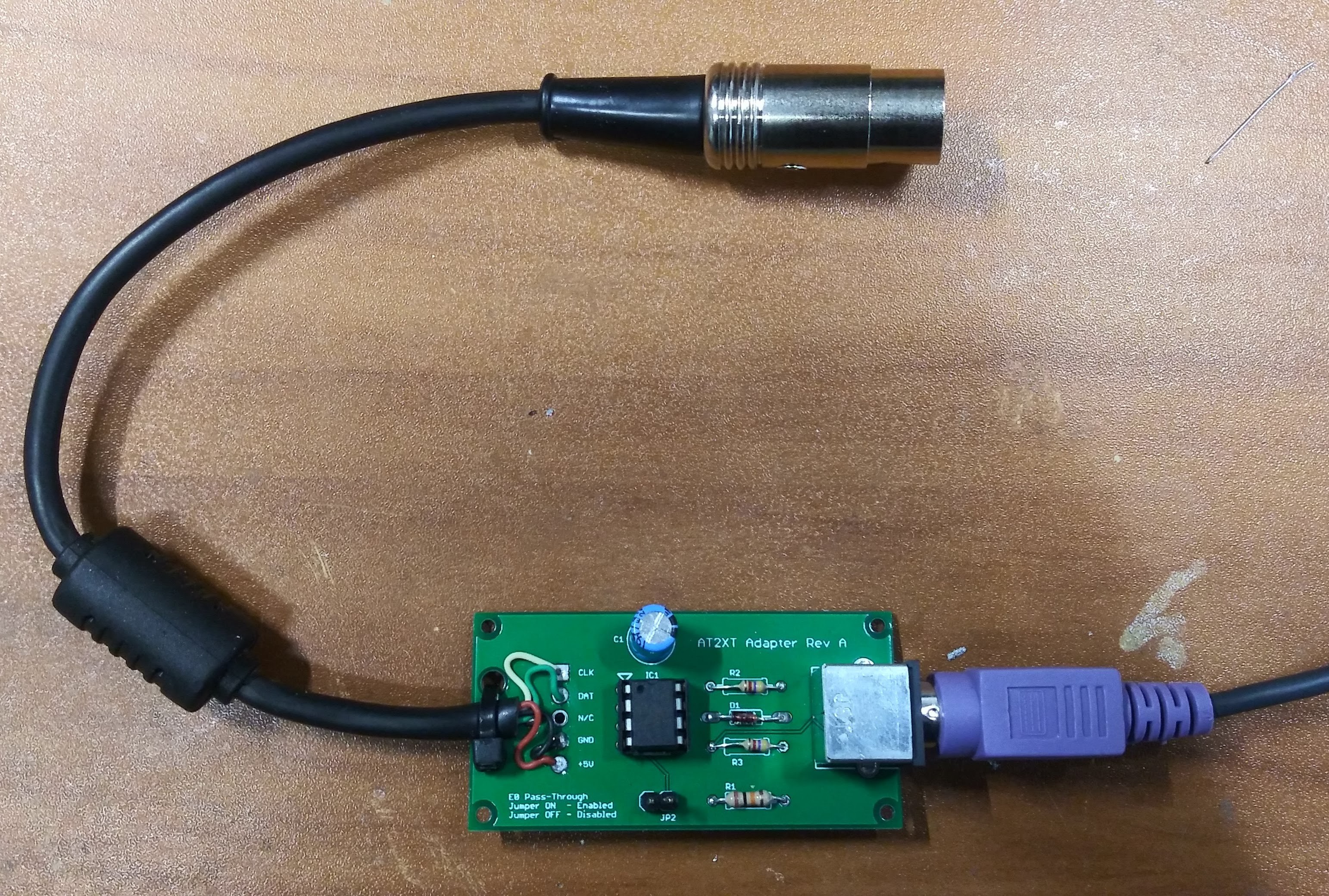
A simple adapter to enable the use of a modern PS2 keyboard on IBM XT computers
To make the experience fit your profile, pick a username and tell us what interests you.
We found and based on your interests.
at2xt-board-reva.zipEagle CAD Design Files - This work is licensed under a Creative Commons Attribution-NonCommercial 4.0 International License. CC-BY-NC 4.0, Copyright (C) 2019, David Anders. All Rights Reserved.Zip Archive - 58.73 kB - 07/08/2019 at 01:14 |
|
|
at2xt-board-reva-gerbers.zipGerber Manufacturing Files - This work is licensed under a Creative Commons Attribution-NonCommercial 4.0 International License. CC-BY-NC 4.0, Copyright (C) 2019, David Anders. All Rights Reserved.Zip Archive - 35.93 kB - 07/08/2019 at 01:13 |
|
|
XTATKEY_RT01.ZIPPIC Firmware Source Code and Intel Hex File - Copyright by Charles P. Guzis, all rights reserved. Chuck Guzis retains all rights to this code, but gives permission to use and modify it for non-commercial, non-profit applications, provided that this copyright notice is reproduced in its entirety.Zip Archive - 14.24 kB - 07/08/2019 at 00:45 |
|
|
XTAT094S.ZIPPIC Firmware Source Code - Copyright by Charles P. Guzis, all rights reserved. Chuck Guzis retains all rights to this code, but gives permission to use and modify it for non-commercial, non-profit applications, provided that this copyright notice is reproduced in its entirety.Zip Archive - 12.22 kB - 07/07/2019 at 23:48 |
|
|
XTATKEY_094.HEXIntel Hex PIC Firmware - Copyright by Charles P. Guzis, all rights reserved. Chuck Guzis retains all rights to this code, but gives permission to use and modify it for non-commercial, non-profit applications, provided that this copyright notice is reproduced in its entirety.x-hex - 2.68 kB - 07/07/2019 at 23:27 |
|
The PCBs arrived today from JLCPCB ! I quickly assembled the board and did some tests. Worked on the first try! The original reference design for this called out 4.7K Ohm resistors which is what i tested with first, however I wanted to see if worked using 10K Ohm resistors as well and it did. I also made the design with large spacing for both the diode and resistors so that you can using 1/8, 1/4 and 1/2 Watt resistors or alternative diodes int he design! After final testing, I mounted the adapter along with the ATX PSU Adapter on a piece of scrap acrylic....
Create an account to leave a comment. Already have an account? Log In.
Become a member to follow this project and never miss any updates