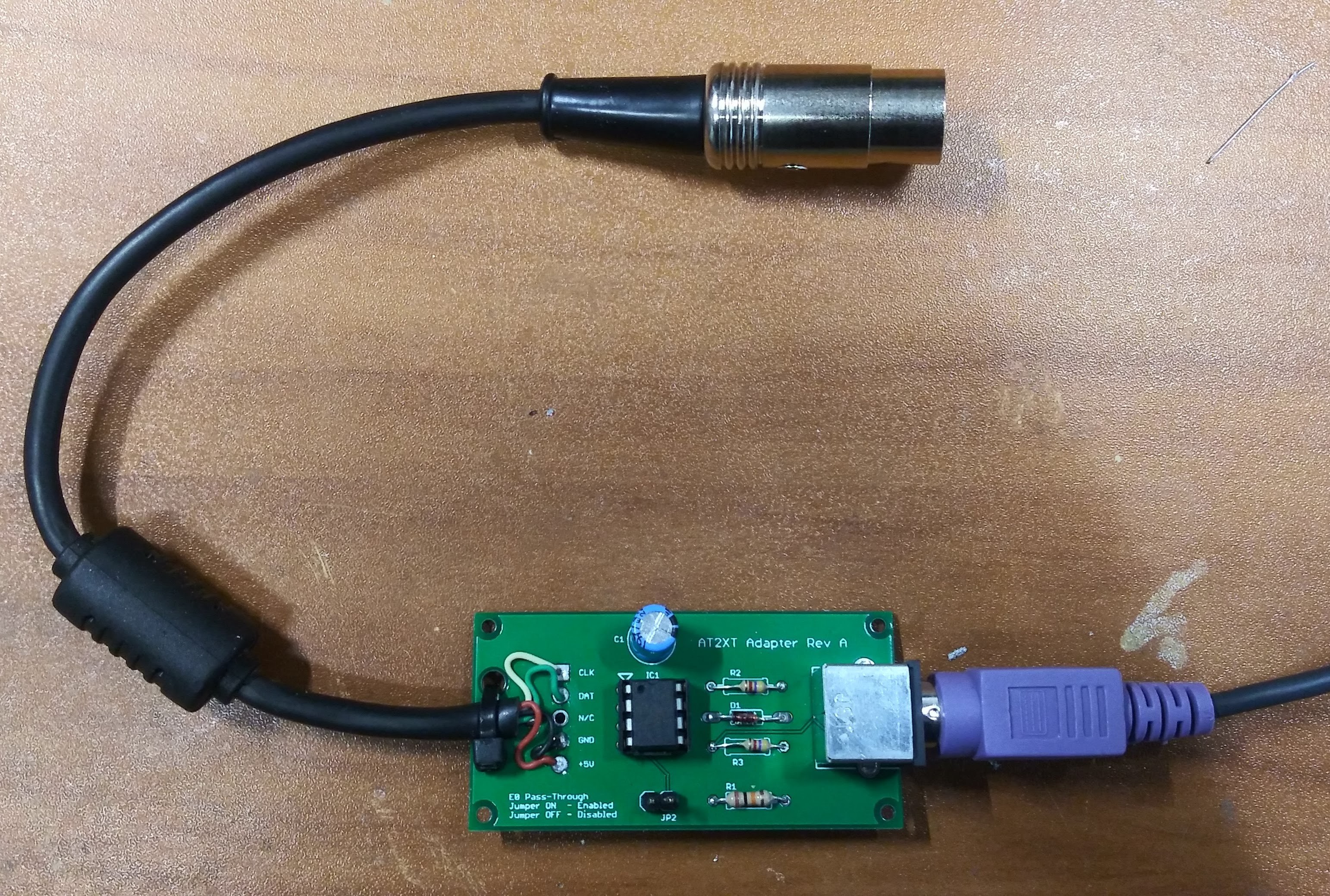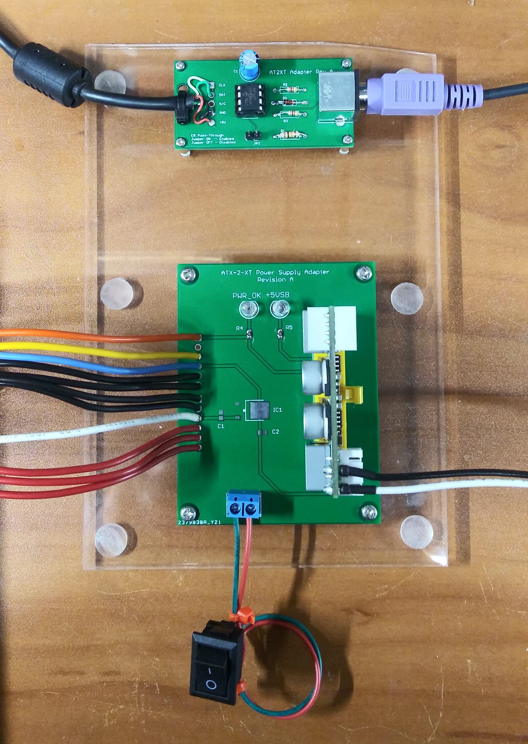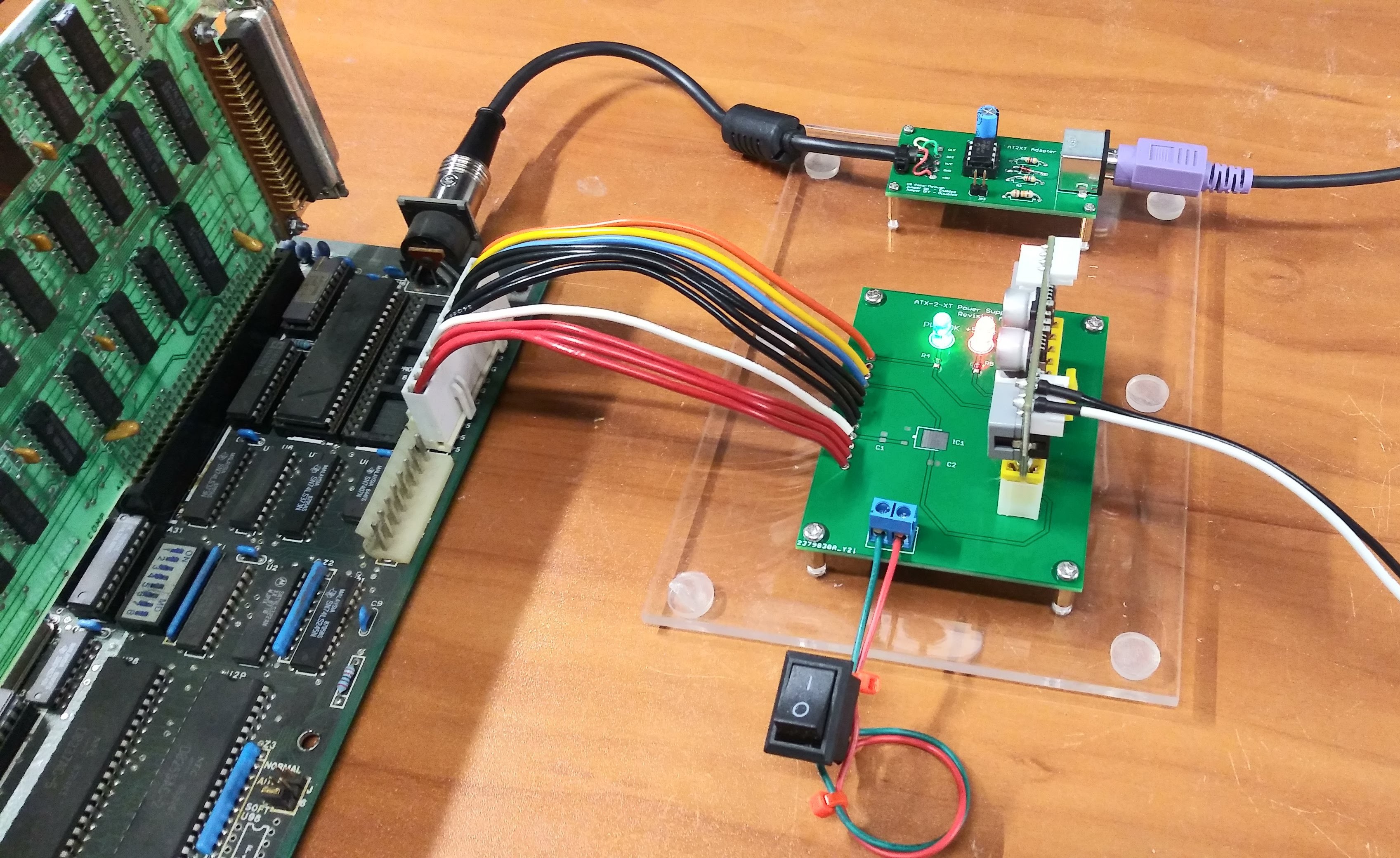
The PCBs arrived today from JLCPCB ! I quickly assembled the board and did some tests. Worked on the first try! The original reference design for this called out 4.7K Ohm resistors which is what i tested with first, however I wanted to see if worked using 10K Ohm resistors as well and it did. I also made the design with large spacing for both the diode and resistors so that you can using 1/8, 1/4 and 1/2 Watt resistors or alternative diodes int he design! After final testing, I mounted the adapter along with the ATX PSU Adapter on a piece of scrap acrylic....


 Dave's Dev Lab
Discussions
Become a Hackaday.io Member
Create an account to leave a comment. Already have an account? Log In.