ReTest - Relay timing tester
Characterise relay performance data as a one-shot or over millions of operations.
Characterise relay performance data as a one-shot or over millions of operations.
To make the experience fit your profile, pick a username and tell us what interests you.
We found and based on your interests.
[ A severe brainfart made me type us instead of ms in this post. It's now corrected. Thanks @Yann ]
I bought three different cheap & small 12 volt relays and tested them at 12.0 volts.
The blue is a SONGLE model SRD-12VDC-SL-C The black is a SONGLE model SRC-12VDC-SH The yellow is a HUI KE model HK19F-DC 12V-SHG | 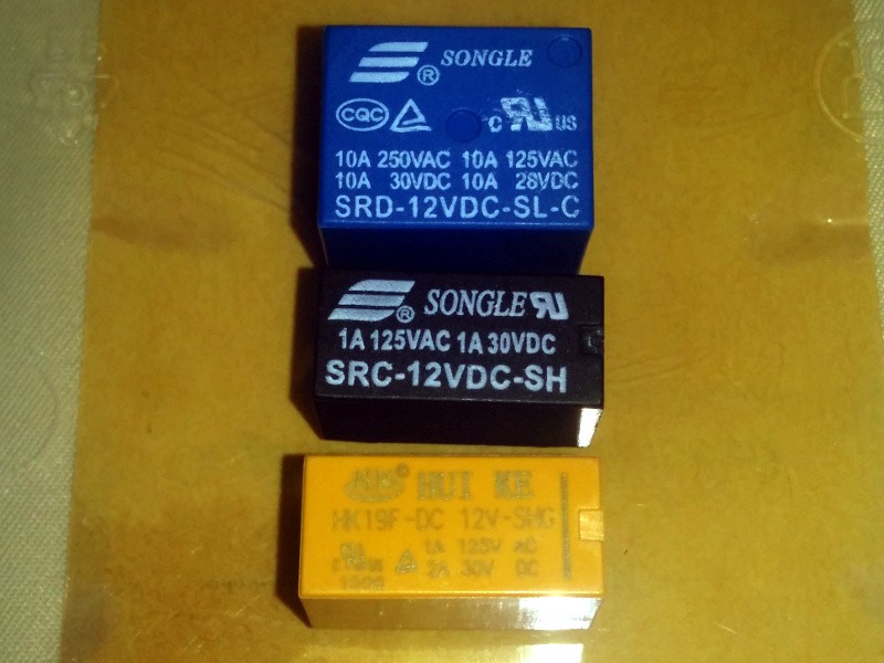 |
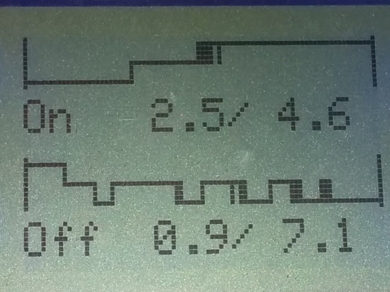
The blue is much more noisy than the two others, probably because it's a bit more heavy-duty supporting up 10 Amps at both 250 Volt AC as well as 30 Volt DC. It takes 2.5ms to start moving the reed after power is applied and then some fast bounces and is stable after 4.6ms. This is about the same as the other two relays. But the de-energizing is clearly different - almost double the time compared to the others to start dropping the reed, and then spending a long time with really slow bounces clocking at at 7.1ms. The spring pulling back the reed in this relay might be very loose to get this bounciness.
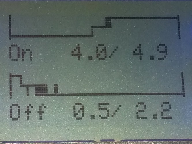
Looking at the other Songle relay, the black one we can see that it takes quite a while to start moving after energizing, but spends less time between the poles and finished up in about the same time as its bigger brother. The de-energizing is just 0.5ms to start moving followed by a short burst of bounces and stabilizes in a nice and fast 2.2ms. So the total time is 7.1ms meaning that we in theory could fully switch this relay on and off at rate of 140Hz
The final yellow HUI KE relay with the same form factor as the black Songle is rather similar in the electrical characteristics as well. It bounces a bit more at energizing and is a tad slower at de-energizing.
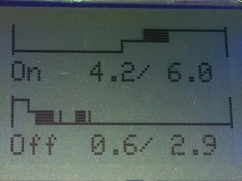
These differences on the black Songle and yellow Hui Ke might just be coincidental and might also show up on different specimens of the same model. I need to get a few of each and see if there are any major variations within the same type....
But first I'll run some tests and see if the 5, 12 and 24 volt models of the relays have any noticeable differences in speed and bounces. And also make some graphs in Excel of the energizing times when the voltage is varied +/-50% of the nominal coil voltage.
To get it all a bit more stable and prettier I soldered 1mm copper wires from most of the mounting holes in the modules and stuck them into a piece of acrylic and just bent the wires over at the bottom. It turned out not too bad in the end... ^_^
I also added the missing boost smps and a dismantled ftdi module (the red at the top left corder) and glued it down onto the acrylic securely so I can use that USB connector as the main supply input. Then I don't risk working any of the connections on the Nano loose by plugging/unplugging the USB connector on it all the time.
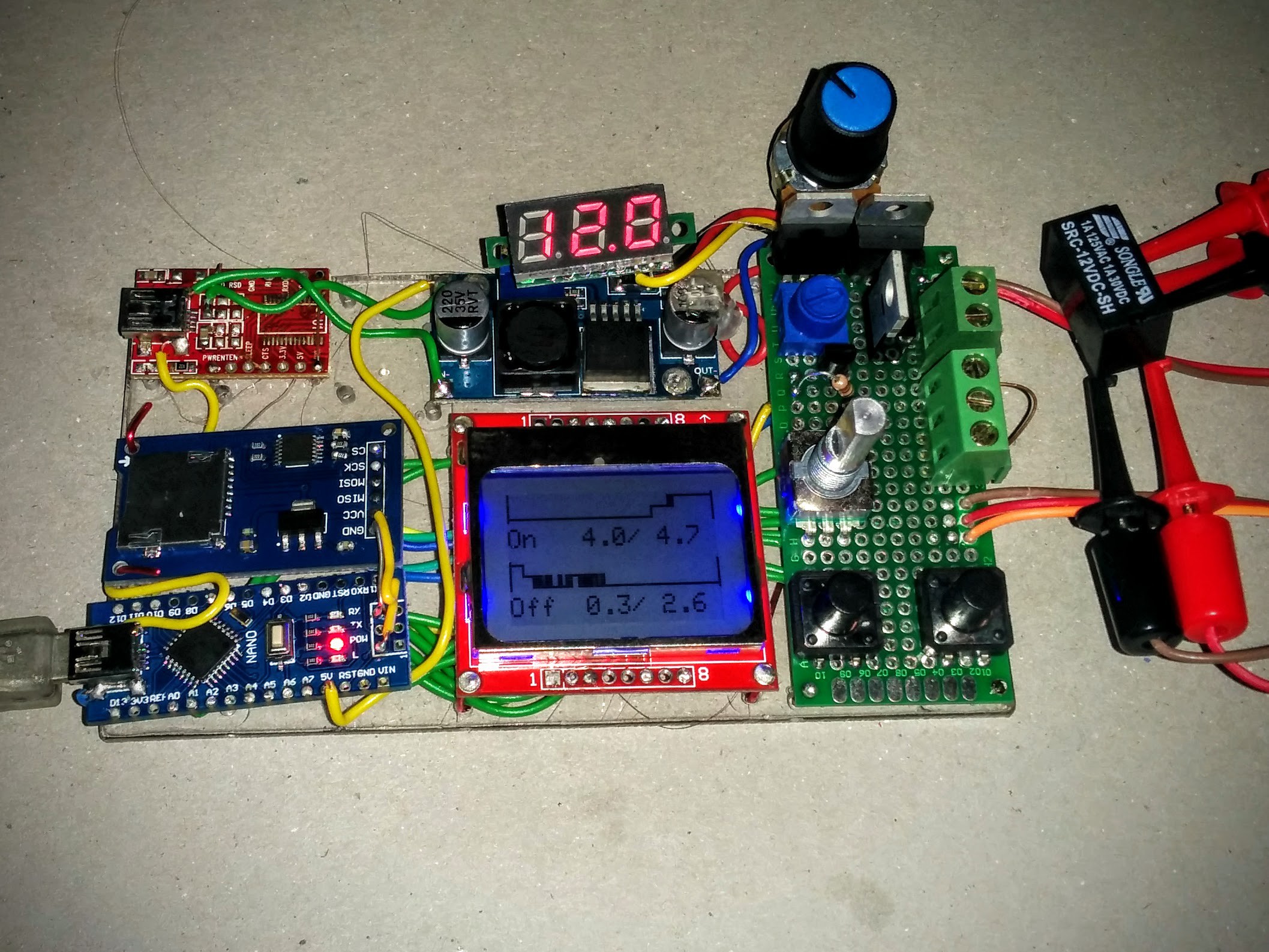
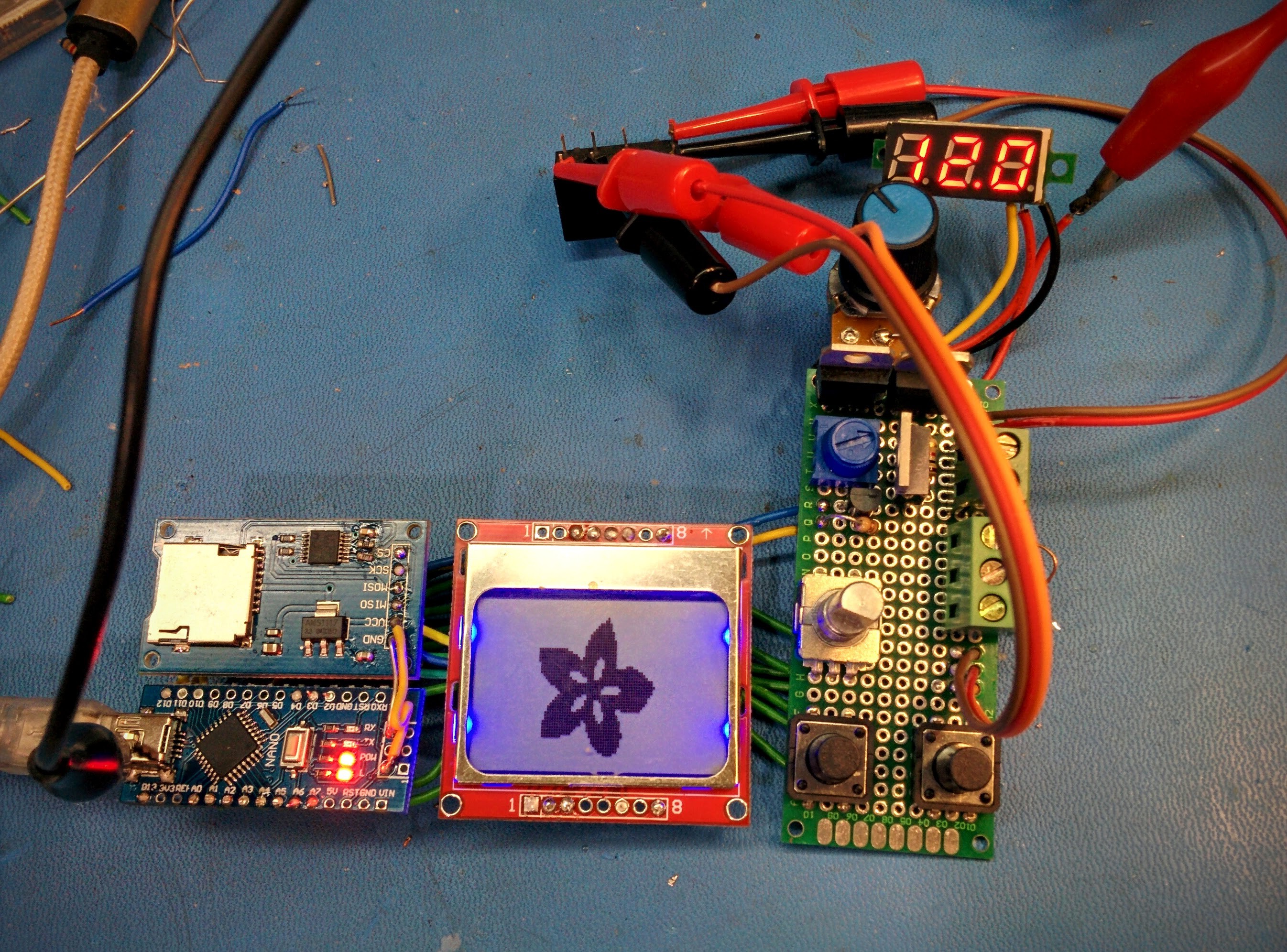
Not having access to my own lab while travelling I used the very nice Makerspace in Penang, Malaysia to just hook up some modules I got by mail order to some parts I got from the shelves of the space to cobble up an ugly contraption worthy of being called a hack. ^__^
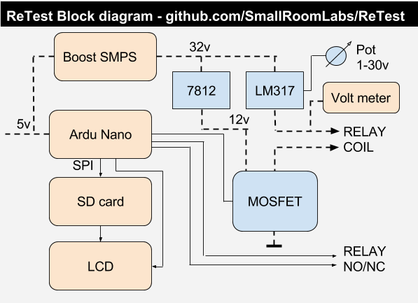
I got an Arduino Nano (not used as an Arduino, just for the '328 on a PCB with USB), a SD-card reader module, a Nokia LCD module, a LED voltage meter module, a boost SMPS module (which I promptly lost, therefore not visible yet on the pictures, a replacement is on order) and a handful of miscellaneous parts like a LM317 variable vreg with a potentiometer, a LM7812, a IRF640 MOSFET, buttons and a Rotary Quadrature Encoder on a small donut board.
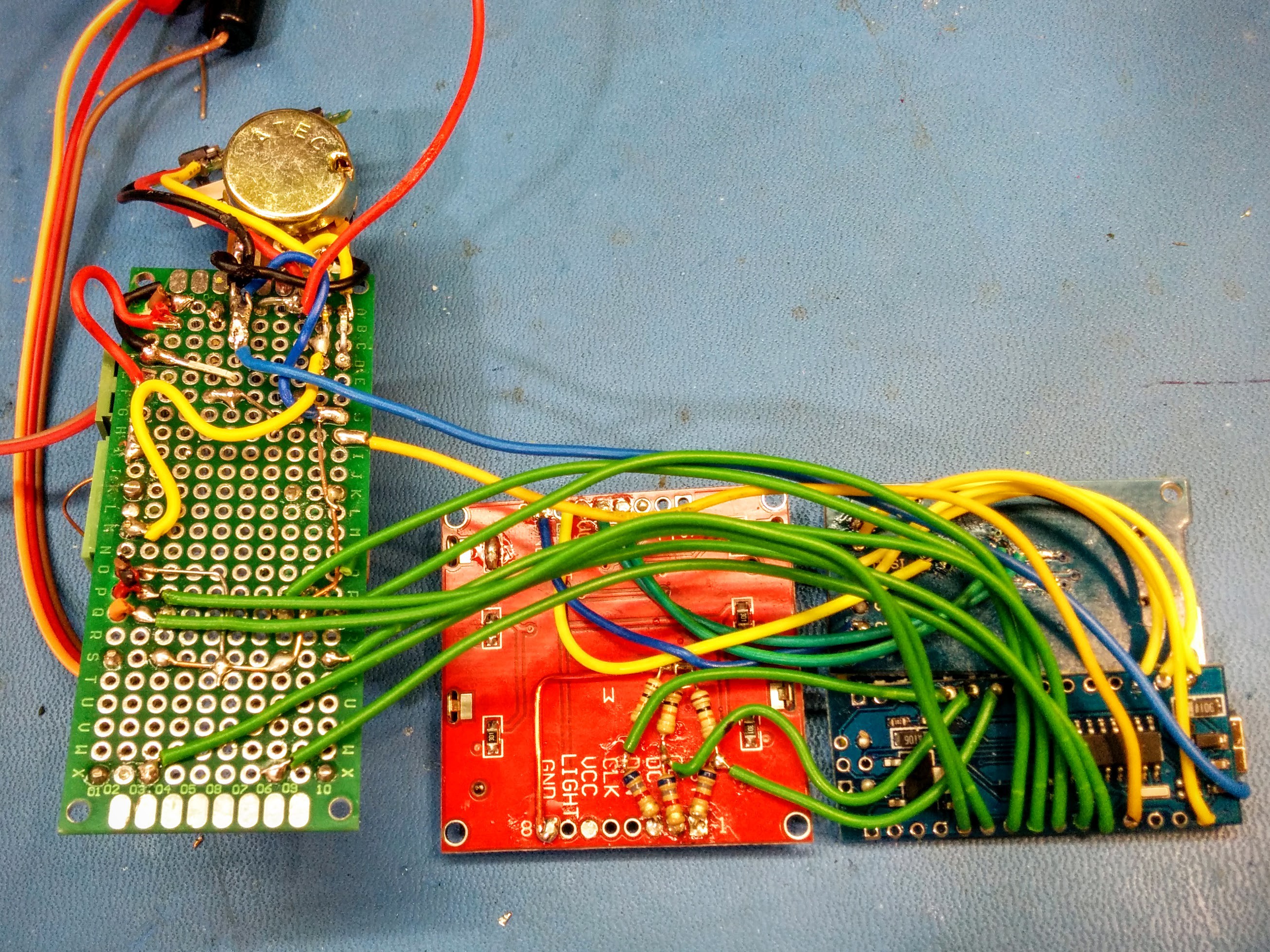
Patched together with single core hookup wires it looks like a total mess from the bottom - the top looks a bit better though. :-)
Create an account to leave a comment. Already have an account? Log In.
Hmmmm good/interesting consideration... Maybe I should include a wet/dry mode in #ReTest-RPi ?
Any plan to enhance the system so it can measure the Von and Voff automatically ?
This would be awesome to create tables like in https://hackaday.io/project/14628-ambap-a-modest-bitslice-architecture-proposal/log/45438-pre-biased-or-hysteresis-relay-logic
Just a remark...
The pins are directly sampled, so there could be unseen events between two samplings....
What about an additive capacitive coupling sample that "latches" a spike or glitch ? something simple like I did with #Discrete watchdog
This way you are certain to catch all the noise...
Yes, this is true. I'm only sampling at 100KHz (10us) intervals. The interrupt handler is today eating up about 50% cpu while running, but with a bit of optimizing I should be able to sample at 5us intervals. This will improve the glitch detection a bit but of course not elliminate lost events.
I actually was thinking of adding a some analog filters, but I had problems with getting somethng working that would handle short connects as well as short disconnects.... :-(
I think I've found a method, using 3×74HC74, a 74HC138, a 74HC253 and possibly an extra gate :-P I might have to create YET ANOTHER project (oh my, not again...)
I could, should and eventually will use such a system !
This will be precious for my curent endeavour #AMBAP: A Modest Bitslice Architecture Proposal
(I use low-voltage coils btw, how do you change it ?)
When can you sell me one ???
The pot in the upper right corner varies the coil voltage between 1.2 and 30 volts, so you can tune it as your heart desires. ^__^
I guess that this will be the only unit - the demand for relay tester can't be that big. So you have to patch one together out of crappy Chinese modules yourself. But you can steal my firmware ^__^
I guess I'll make my own RPi-based version ;-)
Interesting, so the graphs on the screen are showing the bouncing of the relay's contacts...? How are you measuring those "half"-voltages... an ADC, or...?
Great layout, BTW :)
Originally I did plan to use a voltage divider to get a half-voltage and read it with the ADC (like the A in the picture here), but I realised that it would be less a hassle to use two digital pins instead like the B.
If I read 11 on the pins the reed is floating between the contacts, 10 respective 01 is for NC or NO.

Ahhhhhh... you're measuring both sides of the double-throw relay. Great idea, with the two-inputs!
I think I can make a better system with a few HC circuit... I'm currently sketching stuff now :-D
Stay tuned for more hacks.
Groovy
I just saw some "high-speed" relays somewhere... I swear I remember seeing switching-times in the 10s of milliseconds, but this is the only one I'm finding again:
http://www.goldmine-elec-products.com/prodinfo.asp?number=G21707&mc_cid=5410c8e681&mc_eid=2766ec2b15
Clamping circuit:
1. You use a zener diode with a voltage above the supply voltage.
2. You connect its cathode to the drain of the MOSFET
3. You connect its anode to the anode of a silicon diode (1N4148 is sufficient)
4. You connect the cathode of the silicon diode to the gate
Net result: if the voltage at drain rises above (zener_voltage+diode_drop) the gate voltage rises. If the gate voltage rises above the gate_threshold_voltage the MOSFET starts to conduct. The drain voltage is clamped at (zener_voltage+diode_drop+gate_threshold_voltage).
The reason to do this is, that a MOSFET in normal operation can handle much more power than if it just avalanches due to overvoltage. Although the IRF640 is quite sturdy, rated at 580mJ single pulse and 13mJ repetitve. You can use the whole pulse power rating of the device if you use active clamping.
The RC combination has to be a series R-C that has to be in parallel to the coil!
Ah! I understand now. That sounds reasonable... At first I was like What! That will just be a feedback loop that will lock the mosfet in its on-state. But then the penny dropped. I'm not too old to still learn :-) Thanks.
Well, the RC combo I mentioned was not for snubbing, but rather for speeding up the relay when energizing by raising the supply voltage. The cap will then allow the full voltage to be applied while charging and then the current will just pass thru the resistor when the cap is fully charged. This means I can run a 12 volt relay at 24 volts if the resistor has the same value as the coil resistance, but I still get a nice high energy peak at the moment of turn on to really force the relay into action. This without overheating the relay from a continous overvoltage.
Hello Matseng,
Unfortunately I forgot one important detail of the clamping circuit:
You have to place a resistor (1kOhm) between the gate driver circuit and the gate pin(where the diode connects). Otherwise the gate driver would (try to) short out the clamping diodes and the circuit would not work or damage the driver circuit.
Right... I figured out the nessecity of a gate resistor myself. It's kinda obvious. ;-). Thanks for the reminder though.
I would strongly recommend to use a logic level MOSFET, as it is just a relay driver, probably never more than 1A. This would be driveable with 5V, I have some LL FETs with less than 20mOhm R_ds_on. Then you can do away with the linear regulators and adjust the boost module for the exact relay voltage.
I also would think about a circuit against the inductive kick back. In your case it seems to be absorbed by the avalancheing of the MOSFET. This gives the highest demagnetization voltage and thus the fastest switching. This is good for the relay contacts (least wear) but stresses the MOSFET. You can use a zener diode (with anti-serial diode) from gate to drain. This controls the MOSFET for defined clamping. An RC series combination in parallel to the coil is another option. The well known freewheeling diode gives slower switching of the relay.
You could even nicely investigate the differences in switching speed with your circuit.
Agree on the logic level MOSFET, but I didn't want to order anything from a proper electronics supplier like Farnell or Mouser. I just used a local hobbyist level outlet and what I could find in the Makerspace here. Patching in a PWM'ed DAC into the feedback circuity of the SMPS would be rather easy so I'll probably do that in my next iteration of this project (if there ever is one since the current version seems to work pretty well)
Yes, the IRF640 might give up the ghost sooner or later, I guess I should put a high voltage zener across the Drain/Source of it to keep it happy in the long term. But I really don't follow you on the Gate/Drain thingie you mentioned. Please elaborate.
The two green screw terminals are put there for testing different scenarios. One is connected in parallel with the relay and the other in series for testing.
Just by connecting the classic anti-back-emf diode across the relay made the off timing of a 5 volt relay about 4 times as long. A 12 volt relay just doubled the off time. But as expected no change in the on-time.
I'll make some experiments with raising the voltage a bit and then add a parallel R/C in series with the relay and see how much I can lower the on-timing.
Become a member to follow this project and never miss any updates
So, I've been looking into relays for some unrelated project (although I suffer the same ailment as many here, having collected boxes, bins and reels of surplus relays for an eventual clock and/or computer). One of the things I can't get my head around is dry vs wet switching (in other words switching with voltage across the contacts or not). Evidently, for some contact materials/designs, you need to switch current to break through oxide layers on the contacts. Switching zero current can result in high contact resistance, or no contact at all in some circumstances.
The old way around this issue was to get mercury-wetted contacts, but those are long gone (thanks RoHS!) I guess some expensive contact materials can be switched dry, and for some reason reed relays seem OK, too, but they are primarily SPST.
I think in any sufficiently complex relay circuit (computer), you'll probably end up with some contacts that get dry-switched in some states, so it might be best to figure out how big a problem it really is.
So, I'm finally getting around to wondering the best way to modify this system to test the real effects of dry switching the contacts. Maybe have the contacts connected to I/O pins which cn be tri-stated to dry-switch the contacts, then drive one pin and detect the voltage on another?
EDIT: I got so pulled in by this project, I forgot to say much I like the idea. Nice work!