Still not much 'autonomy' but I do finally have everything in place. The Raspberry pi, the Arduino, a 433 MHz radio and the remote control receiver, all neatly packed in the waterproof box at the back.
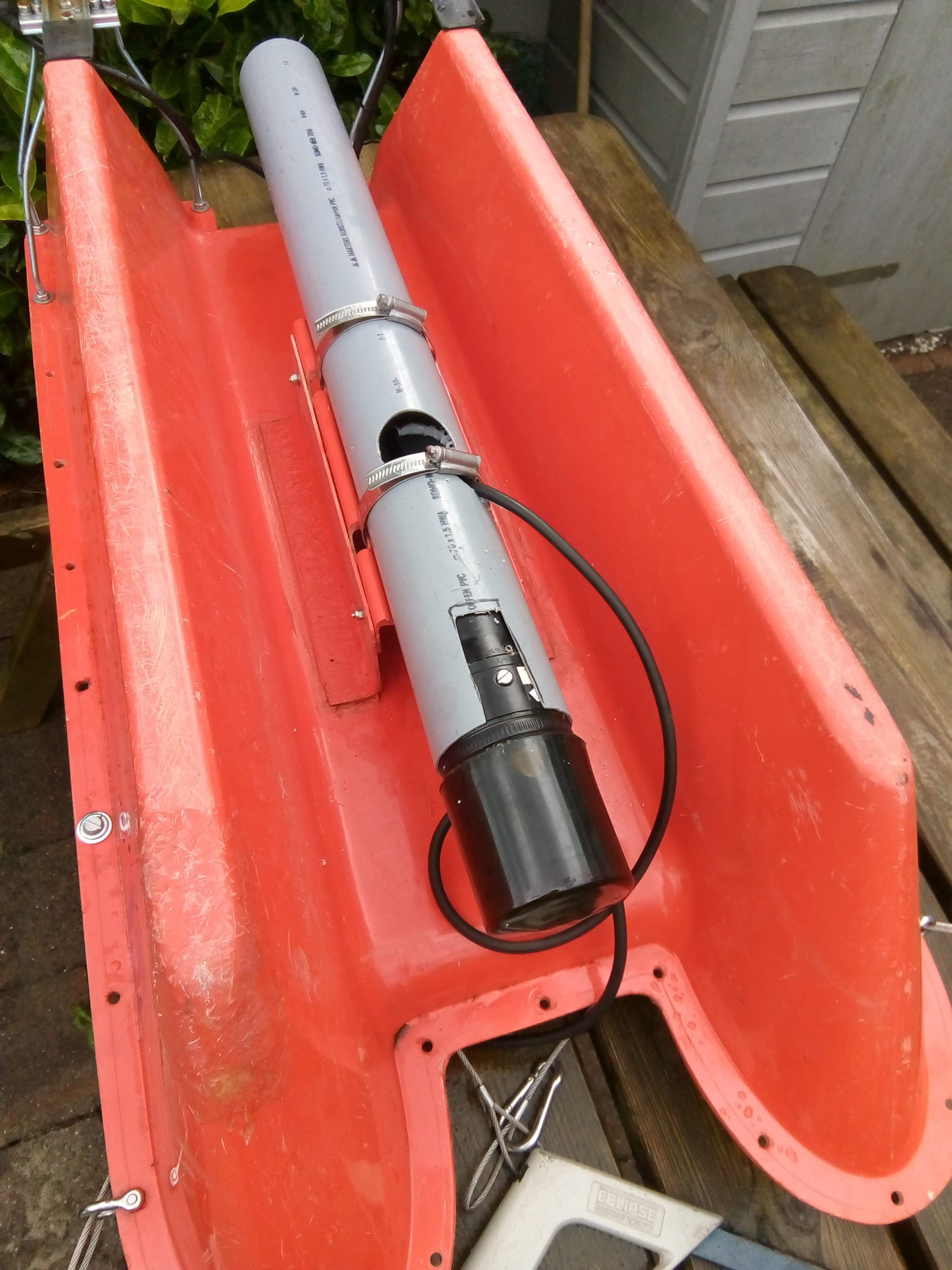
The Scanning Sonar is mounted as well, so I can finally map the lake.
A bit to my surprise it showed a nearly flat bottom, at 80 cm. Then I realized that this sonar works at 1 MHz, and it probably just shows the top of the fluid mud layer. I will need a lower frequency (like 200 kHz) to get to the 'real' bottom.
Since I was writing my own controller software for the Raspberry Pi I first considered taking the shortest path to transferring the the data from my boat to shore: send everything as ASCII text and use a simple text parser to decode values. Easy to write, easy to debug. But a lot of overhead, and since my radio only supports 9600 baud this would seriously limit the amount of data I could transfer. Just create my own binary structure then (maybe using Binary JSON) ? But there is also MAVLink, a standard protocol for transferring data between 'Groundstation' and a Rover (Drone, plane, boat).
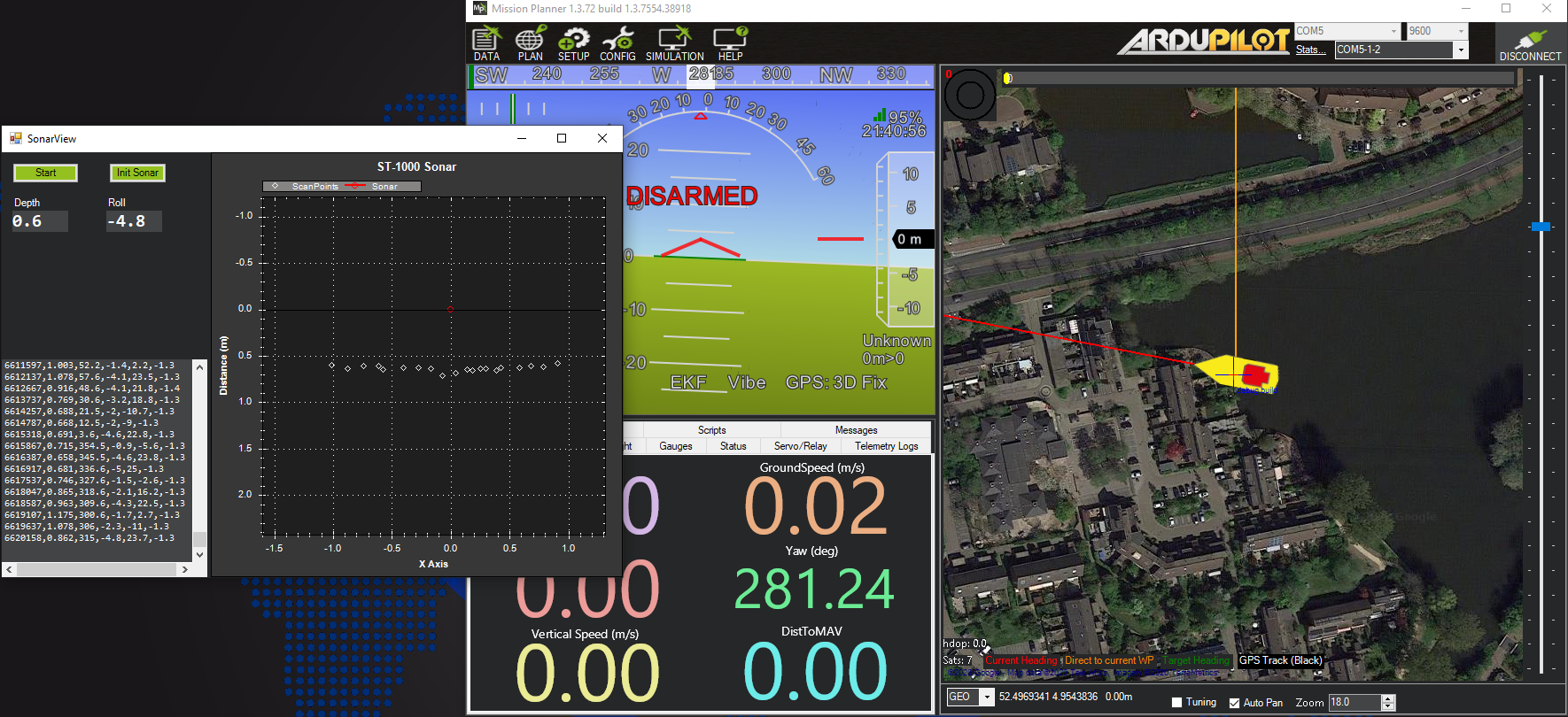
Unfortunately this is also a big project, and although it is not too complicated in the end, the whole documentation seems very intimidating at first. But after a little trial and error I got it going. It helps that the most commonly used groundstation software is MissionPlanner which is open source.
MissionPlanner is also a big project, but as I'm used to C# projects it did not take me long to find my way around. Fortunately it just builds and runs directly if you checkout the whole project and compile it with Visual Studio.
Generating a custom message
For the Sonar I will need a custom message to transmit range, distance etc. This can be added to the 'common.xml' file, which can be found in the MissionPlanner folder:
<messageid="1000"name="SCANNING_SONAR"><description>Scanning sonar.</description><fieldtype="uint32_t"name="time_boot_ms"units="ms">Timestamp (time since system boot).</field><fieldtype="uint16_t"name="range"units="mm">Measured range</field><fieldtype="uint16_t"name="angle"units="0.1 degrees">Angle</field><fieldtype="uint16_t"name="roll"units="0.1 deg">Roll</field><fieldtype="uint16_t"name="pitch"units="0.1 deg">Pitch.</field> <fieldtype="uint16_t"name="yaw"units="0.1 deg">Heading.</field></message>
And that is all there is to it. This simply defines a message with ID 1000 that contains the required filelds.
In the MAVLink folder there is a 'regenerate.bat' file that produces a new C# library from a modified .XML file, and regenerate.bat also contains a line for doing the same for the C library. Which almost works, except for the fact that the 'pymavlink' folder is not complete, and does not contain all the required headers. So I checked out a complete MAVlink set from https://github.com/Parrot-Developers/mavlink. After copying the pymavlink folder to MissionPlanner it works fine.
Processing custom MAVLink messages
Now I defined a new messagetype and named it SCANNING_SONAR, there must be a way to view it in MissionPlanner, but how ? I found the solution in the 'MAVLinkInspector.cs' module. When opened, this window shows the messages as they are received, and even has an option to create a live chart of the incoming data. Key to this interaction seems to be the SubscribeToPacketType function:
So far I connected the GPS to the standard serial port of the Raspberry Pi (Rx/Tx), the IMU to the I2C lines and the Sonar to the USB port. But I will also need a serial port for my radio. So that is one port short. The solution to this could be using a 'software serial port', as you can easily get on any Arduino. But that's not so simple on the Pi. I could find just one library that supports a software serial port : PiGPIO. And that only supports reading. But that could be enough, as I can use that to read the GPS.
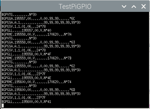
And that works surprisingly well. Connect the Tx of the GPS to GPIO18, and test it using the following code :
Make sure the pigio library is linked in when compiling. In Code:Blocks this is done in 'Project->Build Options', tab 'Linker Settings', add it to the 'Link Libraries' list.
Works great. There is only one drawback in using the pigpio library: it needs root privilege to run. So Every time I start it from the Code::Blocks IDE, it refuses to run, and I have to open a terminal and enter the 'sudo' command to start it. The solution to that appears to be starting Code:Blocks from the XTerm console using 'sudo codeblocks'. That sometimes works, but most of the time gives me a 'Failed to init GTK+' error. But that could be caused by the fact I'm working through Remote Desktop.
So now I have GPS input, and the standard Tx/Rx serial port available for other purposes.
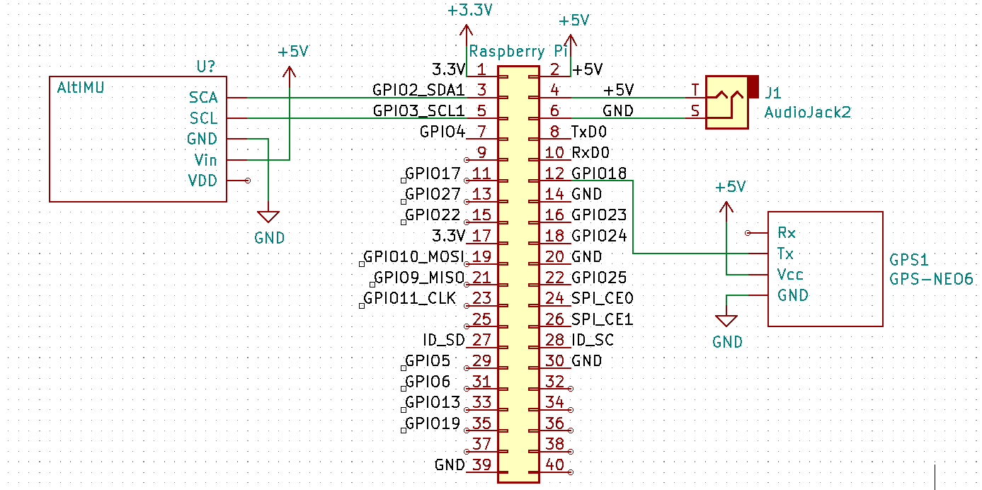
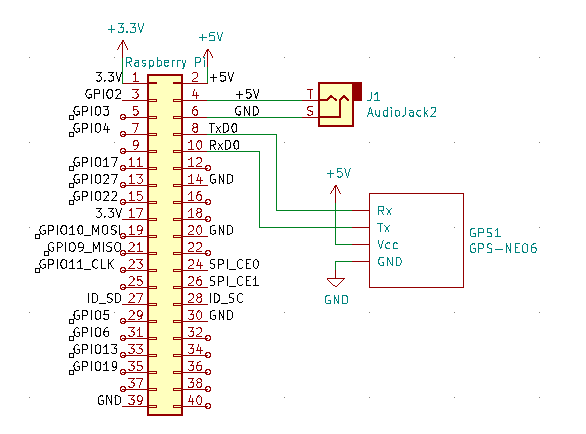
I decided to use the Raspberry Pi 3 A as my main controller for the boat, and the first task was to add a GPS. The NEO-6M GPS module is very standard unit, with lots of examples on how to connect it. It is powered by 5V from the RPi, and the communication is standard RS-232 at the 3.3V level so it can be connected directly to the RPi Tx and Rx. Connecting to the RPi. Yes, it is as simple as that.On the RPi itself, make sure the Serial port is enabled, and the kernel messages on this port are disabled. (Raspi-Config->Interfacing Options->Serial) Now I installed PuTTY (sudo apt-get install putty), set it up for Serial port '/dev/ttyS0' and 9600 baud. This immediately shows the NMEA text messages as they are coming from the GPS receiver. Can't be easier than that.
After adding the GPS receiver it was time to read it. I first tried the GPSD project which tries to make reading GPS data in the background easy. But after struggling some time to get it working I decided it was not what I was looking for. As always with these kind of projects there are many examples and HowTo's , but I assume a lot of them are outdated or just incorrect for the setup that I have so none of the examples worked as described. And since I basically only needed position heading and speed from this specific GPS receiver I opted to use the TinyGPS++ package. This is actually a library written for the Arduino, but only minor changes were needed to get it running on the Pi. My version is here: https://github.com/Cees-Meijer/GPS_Decoder
The whole 'Autonomous' thing is still in the future, but I suppose I'll have to continue. After some failed attempts to create my own remote control using some 'Long Range NRF24 Radios' I gave up ,and simply bought a complete Remote Control with 6 channel receiver. The HotRC HT 6A seemed like a good (cheap..) choice.
It's a cheap remote control unit, preconfigured for use with model airplanes. Which means that the controls assigned to specific channels and the output ranges are different per channel. The speed control channel (nr.3) outputs a PWM signal of exactly 1000 to 2000 uS, but the direction channel only has a span from 1200 to 1800 uS, probably optimal for controlling the rudder servo.
The boat only has two thrusters, and no rudder. So all the steering has to to be done by varying the thruster speeds. And if we for example are going forward and want to steer a little to the left, the left thruster has to slow down. But for a sharp turn the left thruster eventually even has to run in reverse. A complicated math thing, so I left this to my daughter who studies maths at university... And she came up with a reasonably simple relation between speed and direction that could be used to control the motors. This of course required some intermediate processing so I added a Arduino Pro Micro to translate the RC PWM signals to the appropriate thruster signals
Despite all numbers seeming to be correct, the boat reacts quite unpredictable. Only full speed ahead seems to work fine, but breaking and reverse is not working, or very slow. After checking and re-checking the code I finally find the answer in the user guide of the ESC. By default the ESC has some behaviour that is good for using in an RC Car, but not for the boat. Fortunately I bought the ESCs with a 'Programming Card' which makes programming easy. First I had to modify the break-behaviour. By default the system breaks the motors to a halt if you suddenly pull it to reverse. But I want it just to go in reverse, no stopping. Second I set the maximum reverse power to 100% instead of the standard 25% .
Later I found out that this is actually known as 'skid steering' and supported by ArduPilot (https://ardupilot.org/rover/docs/rover-motor-and-servo-configuration.html#skid-steering) as well. And the code for this comes pretty close to what we figured out. (look for the void AP_MotorsUGV::output_skid_steering(); function in the ArduPilot Rover code.
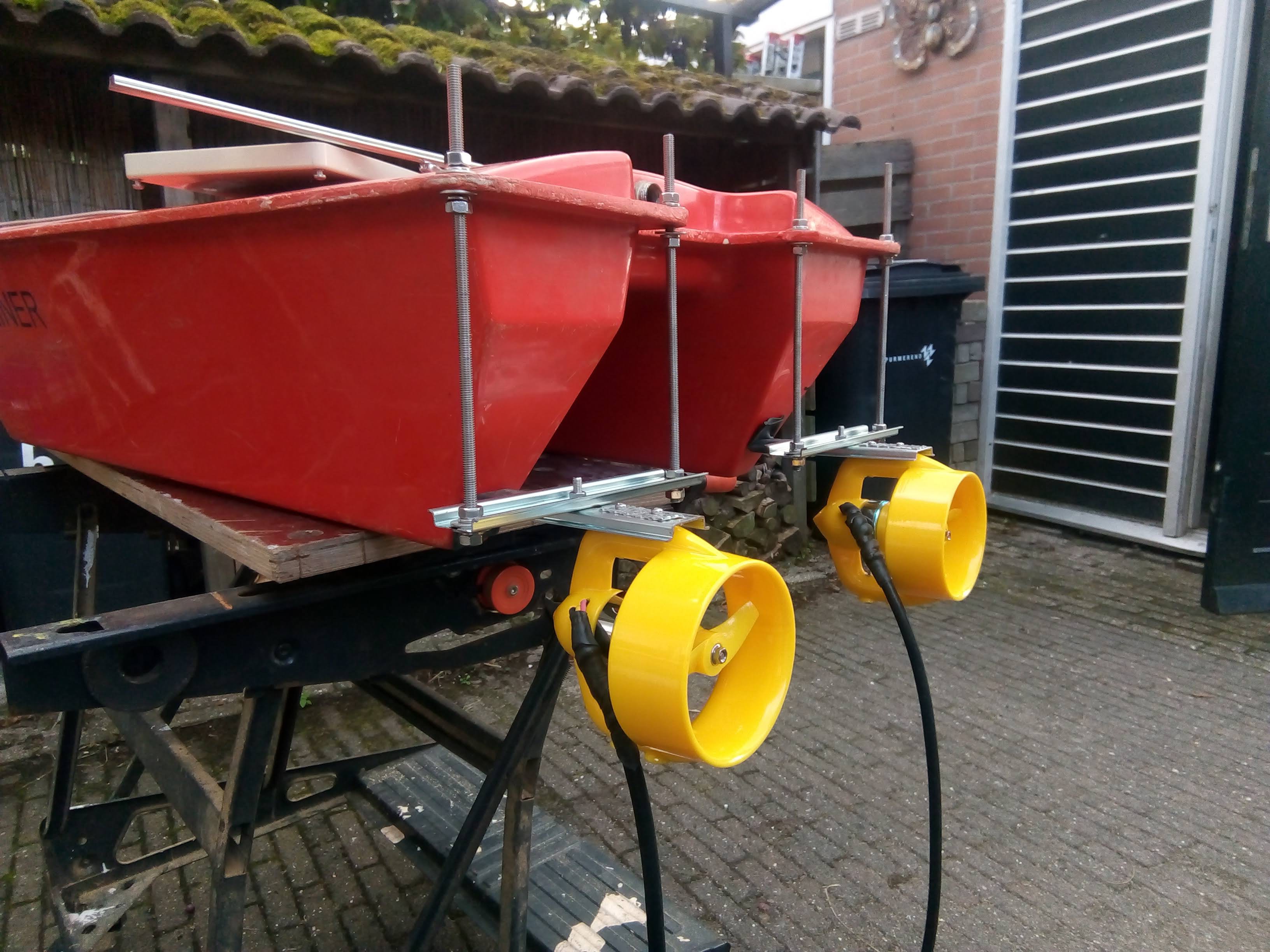
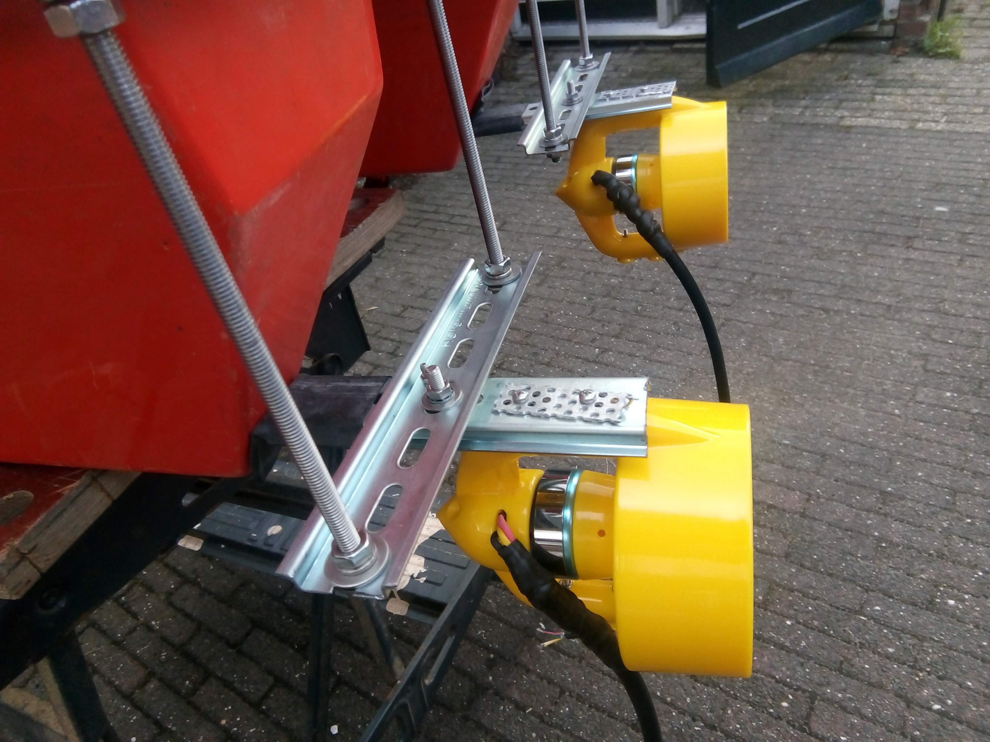
Finally a nice day, and some spare time so I could mount the thrusters to the boat. I used some stainless steel M6 threaded rod and some DIN rail. DIN Rails is great. It's cheap, has mounting holes and it is very stiff due to the shape.
I kept plenty of length on the M6 rods so I can adjust the depth of the thrusters later, if required.
Once all nuts are tightened the whole construction became quite rigid so it seems like this is going to work. The only thing that worries me is that the metal is sticking out quite a bit to the side and that it will definitely collect weed and algae.
A remote controlled is nothing new, and a lot of the required electronics and controllers is widely available. But if you are not an Remote Controlled Vehicle (RC-)enthusiast, a lot of the words and abbreviations used on the HobbyKing RC pages are not immediately obvious.
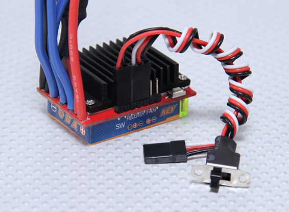
First, I will need something to control the speed and direction of the thrusters. The motors are so-called 'brushless motors', which need special drive electronics. This is called an ESC or 'Electronic Speed Controller'. Then I found out after ordering my first pair of ESC's, not all ESC support changing the direction. Which makes sense if you use it to power a plane or helicopter. So I ordered a second (more expensive) pair 'with reverse'.
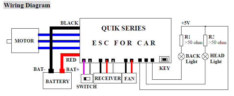
Now, as I said, I'm a newbie in RC, so first I did not know what 2-3S means. This appears to be the number of standard 3.7V Lithium cells as connected in Series. So '3S' is 11.1V. Next is the 'BEC Output'. BEC stands for Battery Eliminator Circuit. Which is not a device to actively destroy your batteries, but simply an on-board regulator that provides a regulated 5V DC for powering your external electronics so you do not need an additional power supply or battery for that. Great. Unfortunately the user manual is very extensive on the programming of this unit, but not very detailed on the connections.
The contacts used for controlling the ESC are simply labelled 'RECEIVER'. Probably very obvious to anyone, except me. Now I think that the Red and Black wire are the BEC (5V) output, and the white wire probably carries the servo signal.
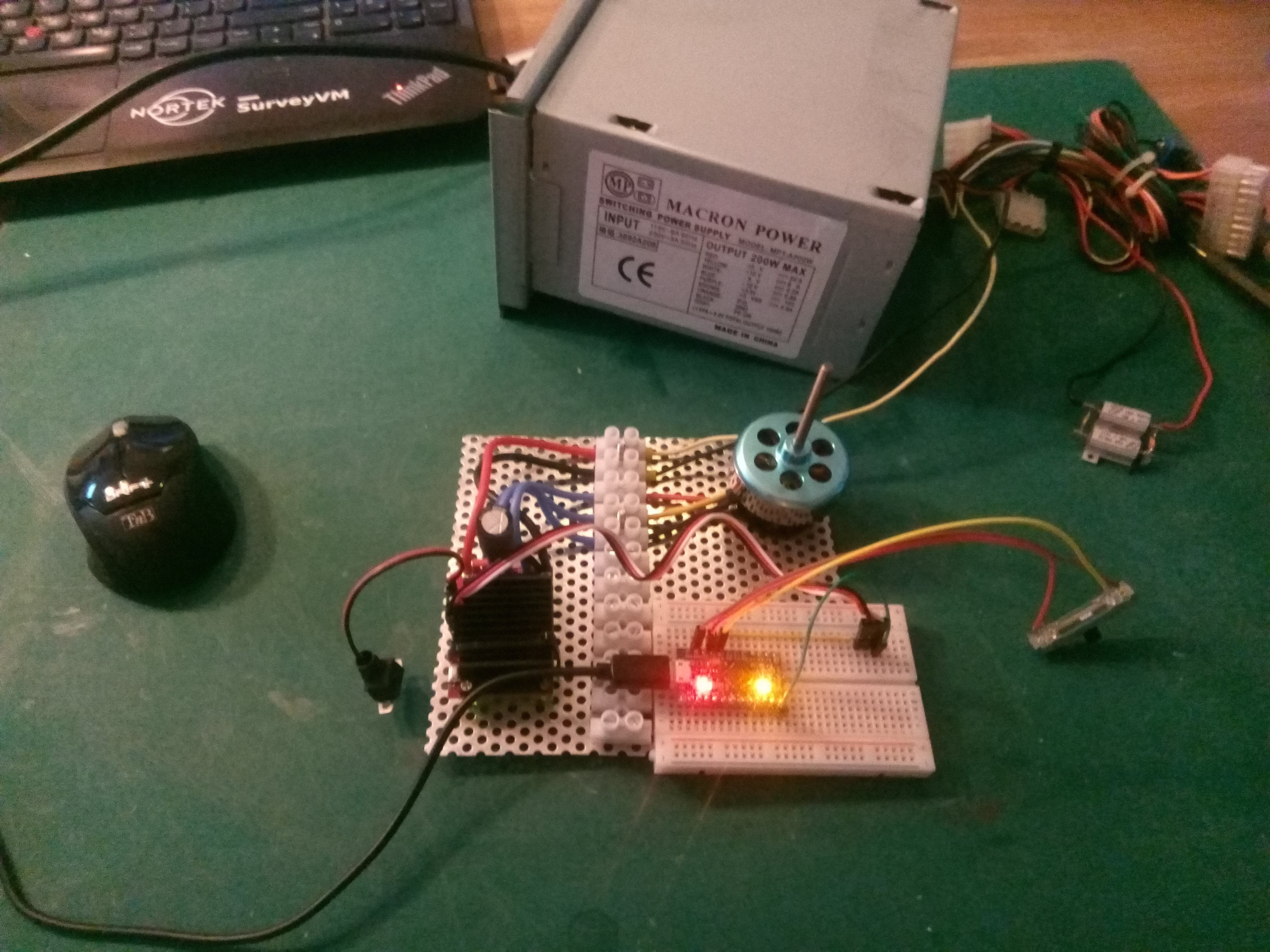
Test setup with one motor and a potentiometer as a speed regulator
Using an old PC power supply that can supply 12V at 8A and a Arduino Micro I just hook up a quick test setup. The 'Servo' library is used to generate servo compatible signals. A potmeter is attached to the analog input so I can change the servo signal. This is the test sketch:
int YaxisInput = A2; // select the input pin for the potentiometerint XaxisInput = A3;
int XValue,YValue;
int Motor1 = 9;
int Motor2 =10;
#include<Servo.h>
Servo ESC; // create servo object to control the ESCvoidsetup(){
pinMode(YaxisInput,INPUT);
pinMode(XaxisInput,INPUT);
ESC.attach(Motor1, 1000, 2000); // (pin, min pulse width, max pulse width in microseconds)
}
voidloop(){
XValue = analogRead(XaxisInput);
YValue = analogRead(YaxisInput);
XValue = map(XValue,0,1023,0,180);
ESC.write(XValue);
Serial.print(XValue); Serial.print(","); Serial.println(YValue);
delay(10);
}
And that works. After applying power, and switching the ESC on, it generates some 'beeps' using the motot itself which scared me at first.. But the beeps are an indication that the ESC detected the neutral throttle signal (the servo output from the arduino) and the power. After that, moving the potmeter controls the motor speed and direction just fine. Only when moving the controller too fast from one side to another so the reversal of the motor is very fast, the powersupply switches off. Probably the reverse current is too much for the powersupply protection.
So the thruster parts arrived way faster than I expected from Russia.
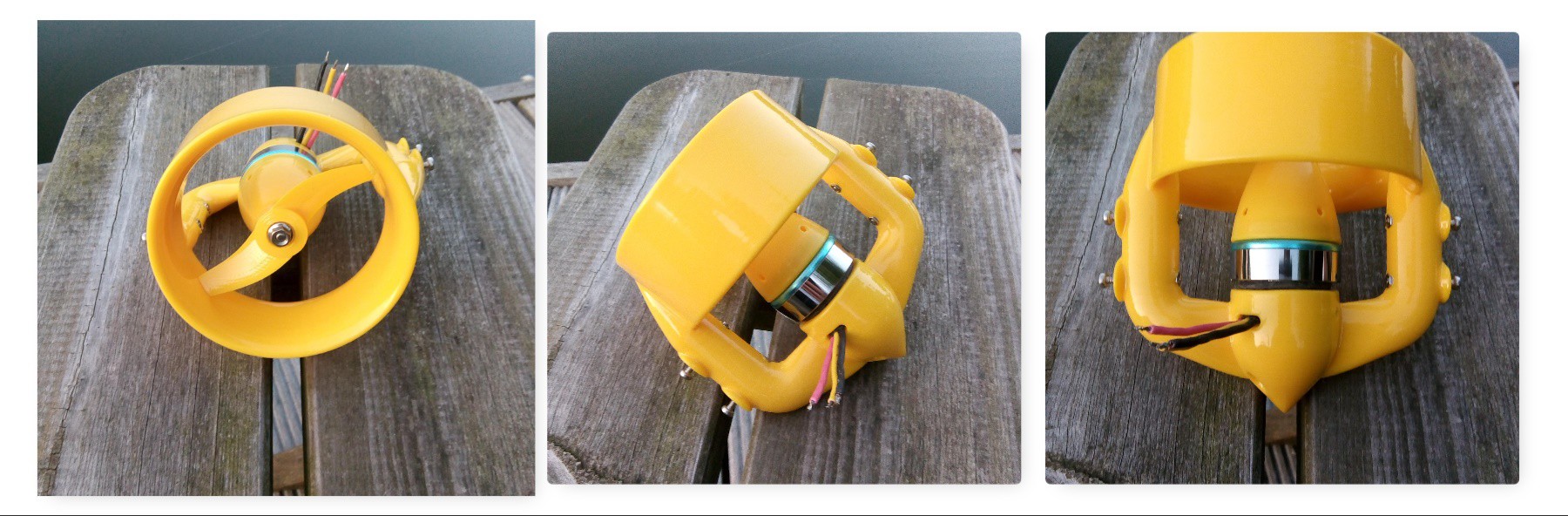
And they look great. Not sure how they did it, but they are very nicely printed and have a real smooth finish. Included in the box is a bundle of printed instructions for assembly. All of which are also available online, but it's nice to have them in print too. What is remarkable though is that though every aspect is of the mounting and modifying of the motors is described and illustrated using photos, there is no assembly drawing of the completed thruster. So up-to the moment I was actually assembling it I still did not really have a good idea of how it would work.
2 Component epoxy moulding material
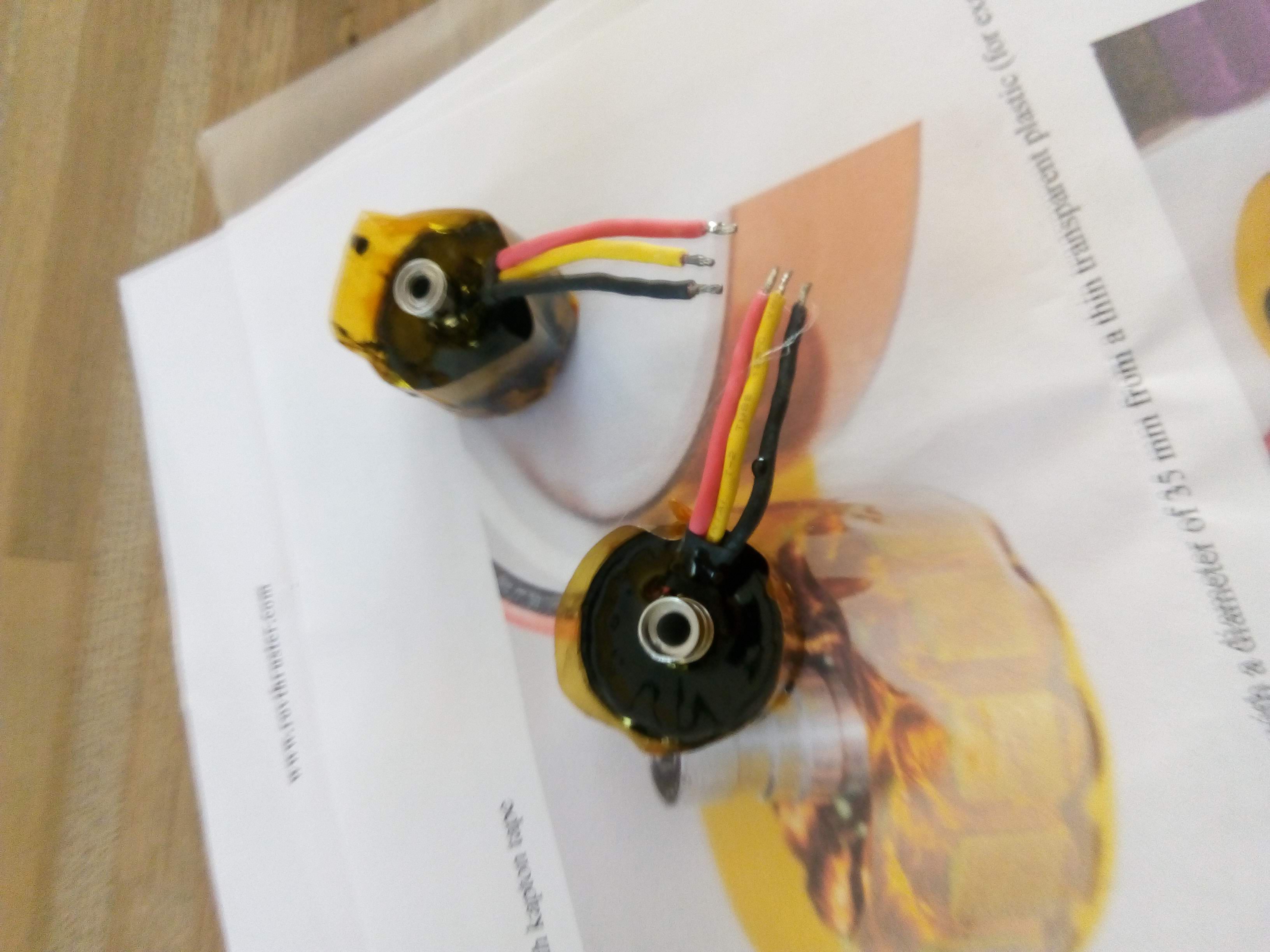
The first step is preparing the motors for underwater. the instructions mention using a slow-curing epoxy glue, but I actually used some 2 component epoxy moulding kit that is specifically designed for moulding sub-sea cables and connectors. It comes in a convenient package where the two components are separated by a removable seal.
So I created the moulding form around the motor using Kapton-tape as shown in the instructions, mixed the epoxy and poured it in. After mixing the epoxy a little bit too long it was already getting warm and started curing while I was pouring it in. Which made it look like it was not filling all the gaps. But after the mix has cured and removing the tape, it turned out to have worked really well. Just a few bubbles got trapped, leaving some of the copper exposed, but these were quickly filled using some epoxy glue.
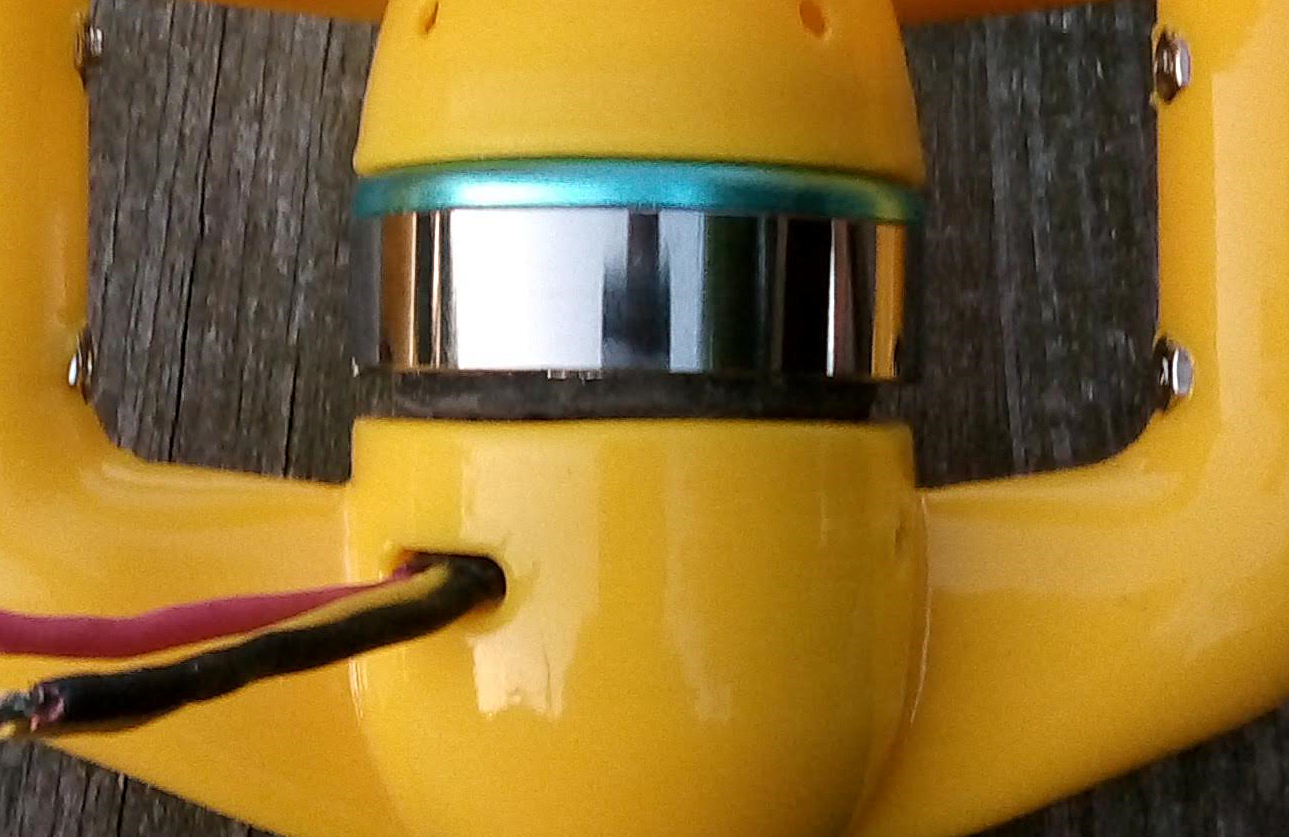
It was only after I started assembling it that I noticed that the epoxy layer was actually a bit too high. Some filing was required to round off the edges, so the motor would fit the thruster housing.
Epoxy in the gap between the motor and the plastic
 Cees Meijer
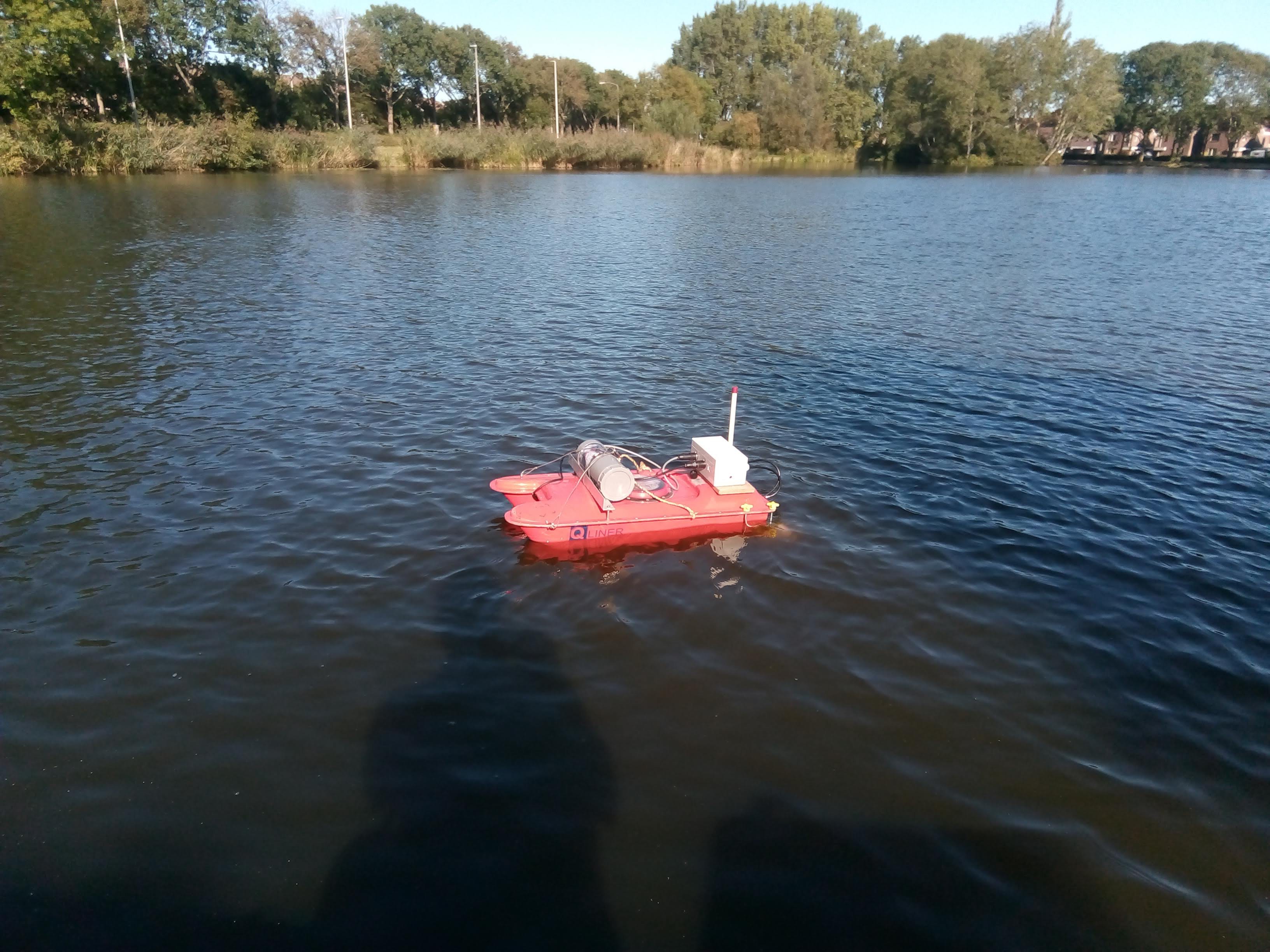


 Make sure the pigio library is linked in when compiling. In Code:Blocks this is done in 'Project->Build Options', tab 'Linker Settings', add it to the 'Link Libraries' list.
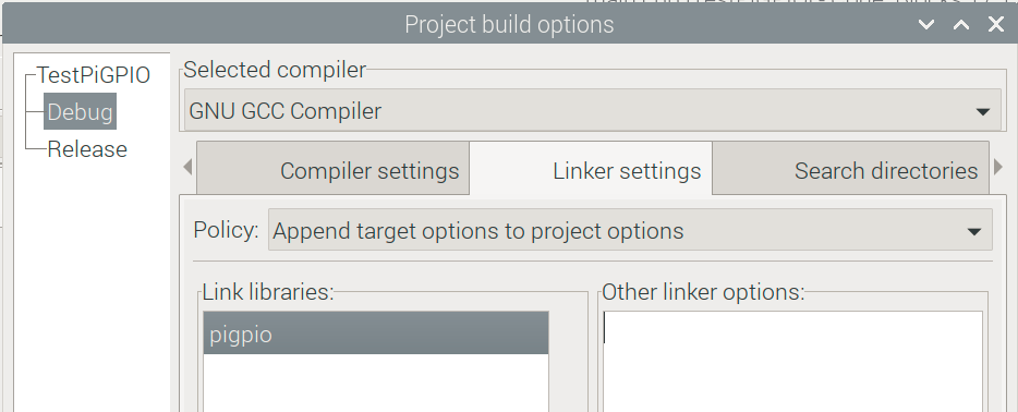
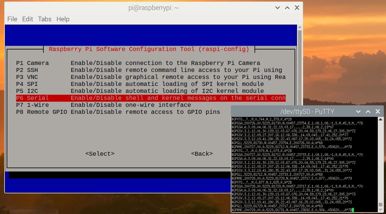 Now I installed PuTTY (sudo apt-get install putty), set it up for Serial port '/dev/ttyS0' and 9600 baud. This immediately shows the NMEA text messages as they are coming from the GPS receiver. Can't be easier than that.
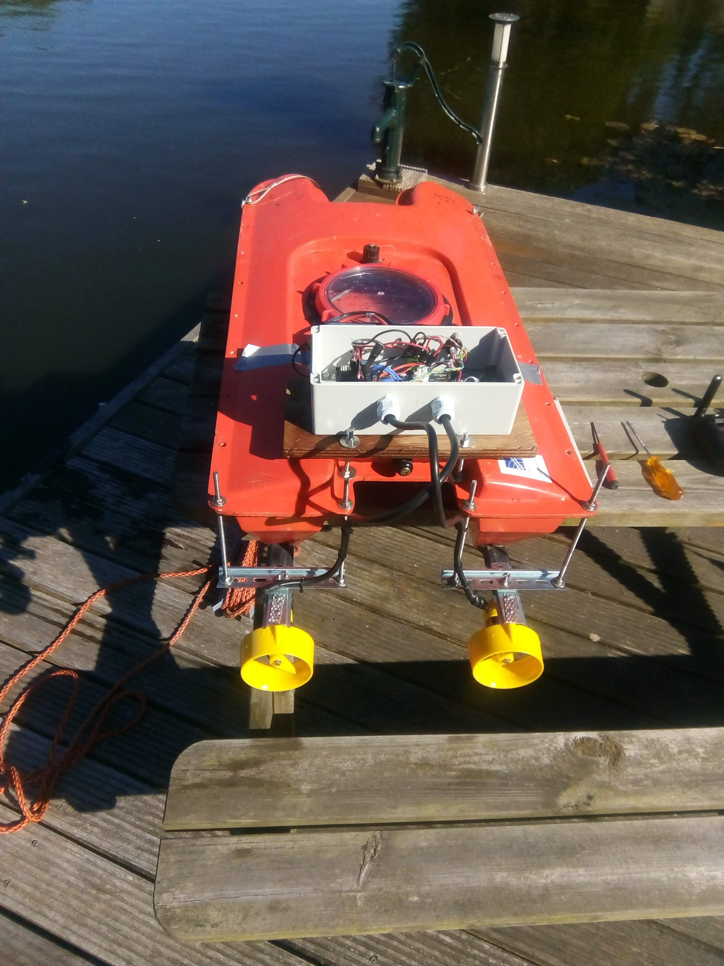


 So now I have two thrusters. In the mean time my