-
1Program the ESP32
Start programming your ESP32-WROOM with the firmware you can find here:
https://github.com/Shyri/gba-bt-hid/tree/master/esp32
I recommend to use one this programmers:
![]()
This project was tested with ESP-IDF v3.3.2 that you can find here:
https://github.com/espressif/esp-idf/releases
You also will need to install btstack. Commit https://github.com/bluekitchen/btstack/commit/a0a4507b35ea396d076a62a67efb1a5a800c5ff9 is the most recent version that is proved to work in this project.
Just follow the ESP32 environment instructions here
https://docs.espressif.com/projects/esp-idf/en/latest/esp32/get-started/
Plug the ESP32 into the programmer. Plug the programer to the pc. Get to the code directory and run 'make flash'
-
2Getting the link port connector
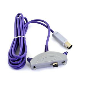
I recommend to buy one of this GBA-GC cables knock off they sell.
![]()
They will provide both a link port connector plus a case where you will house the device and will attach nicely into your GBA.
Disassembling it and desolder the link port connector. Be careful here and don't rush, the connector is mainly made of plastic and if you lay the soldering iron for too long it will start to melt and it wont plug correctly into your GBA later.
-
3Cut a small PCB
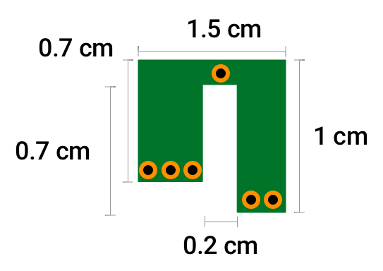
You may have notice the PCB that comes in the GBA-GC adapter has a special shape so that the connector doesn't come off the case whenever you pull the adapter from the top of the GBA. To make the same thing I cut I piece of perfboard with this sizes:
![]()
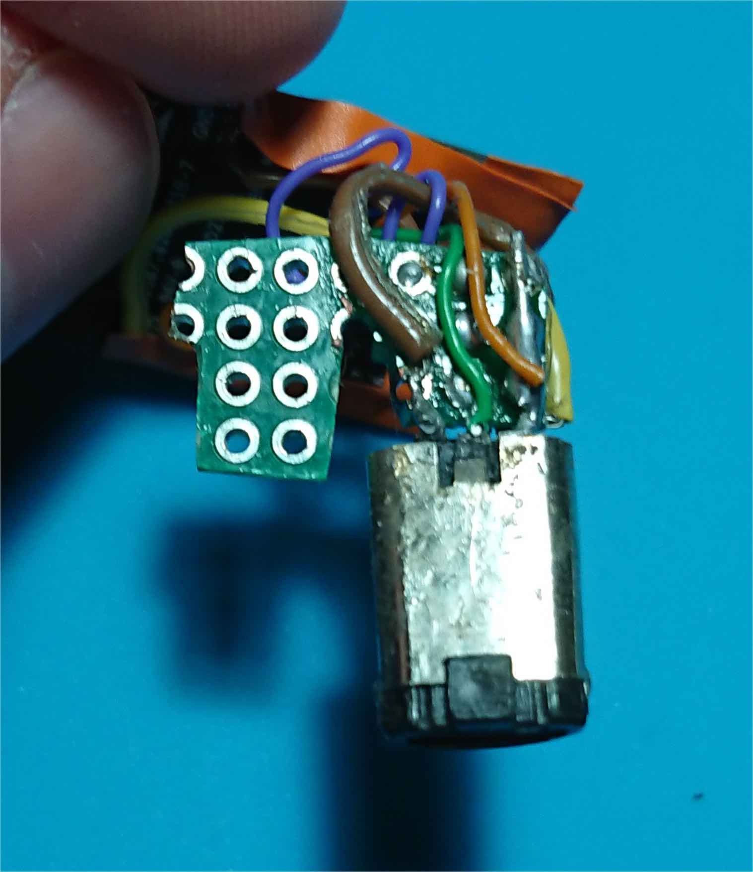
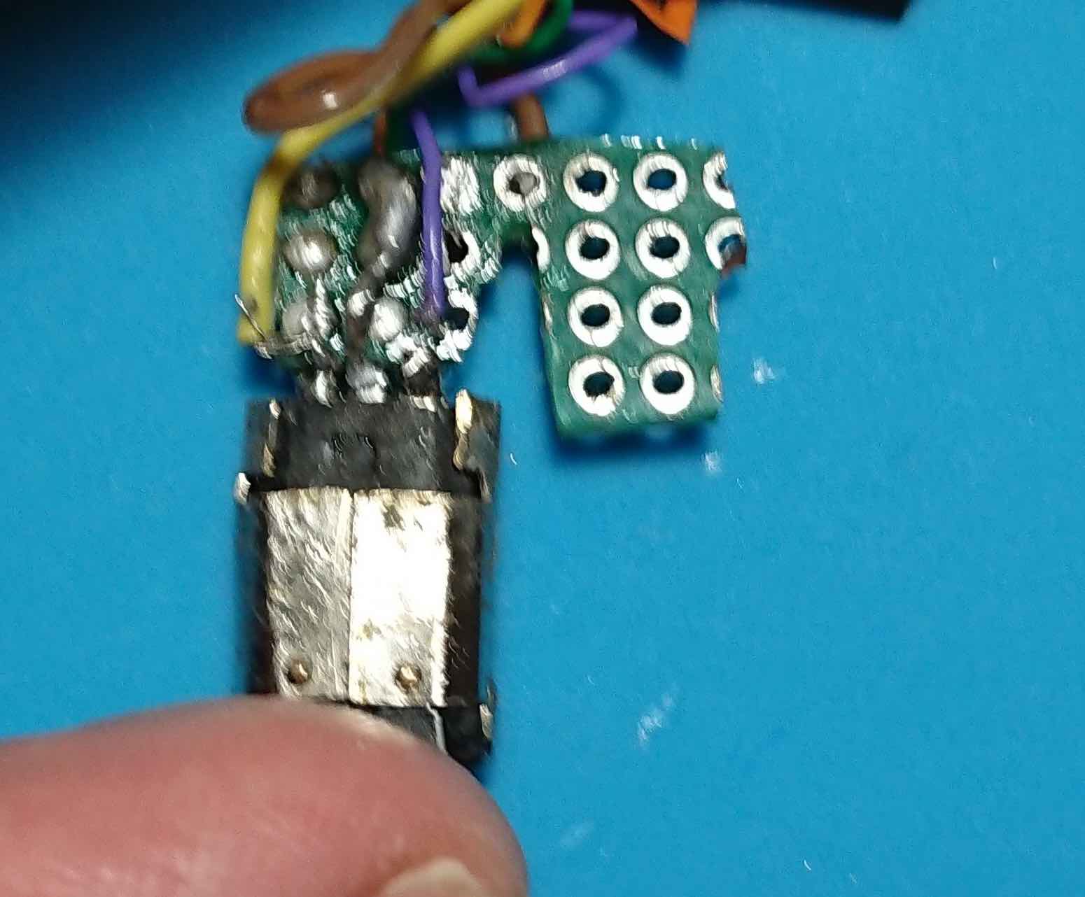
You can use the wholes as a reference if you don't want to take out the ruler to measure. Now we need to stick the link port connector to the leg that is three holes in width. In the diagram above you would place the connector in the left leg and the bottom of the connector would point outwards the screen. Keep in mind that wholes connect both sides of the perfboard and we don't want to short the link port pins. What I did was soldering the pins of one side of the connector to the first row of holes, and on the other side solder the other three pins to the second row of holes trying to avoid contact with the first row. Little rough but it works.
![]()
![]() There... this will stop the connector from popping out of the case and at the same time will make easier to solder cables later.
There... this will stop the connector from popping out of the case and at the same time will make easier to solder cables later. -
4Wire the connector to the ESP32
![]()
Following this diagram wire 5 connections from the link port to the ESP32 pins. Remember to short EN with 3V3 otherwise it won't work.
-
5Adapt the case
Now that we have it wired, you could test it and see if it works.
![]()
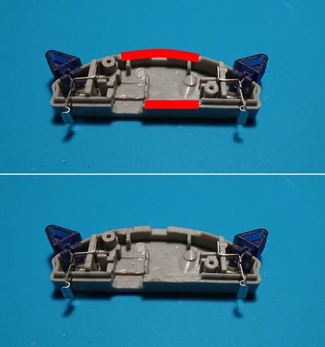
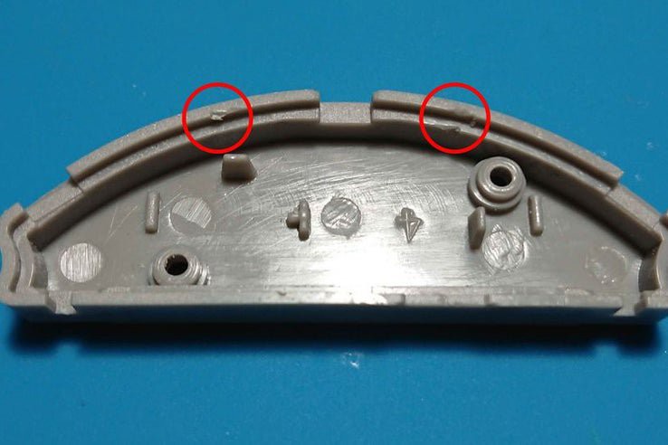
Once tested we can proceed to place it in the case. To make it fit we'll need to carve the case in a couple places. You can see in the pictures where you have to carve in one side of the case.
![]()
In the other side you can make just a couple very very light notches to match the ESP32 corners.
-
6Finishing up
![]()
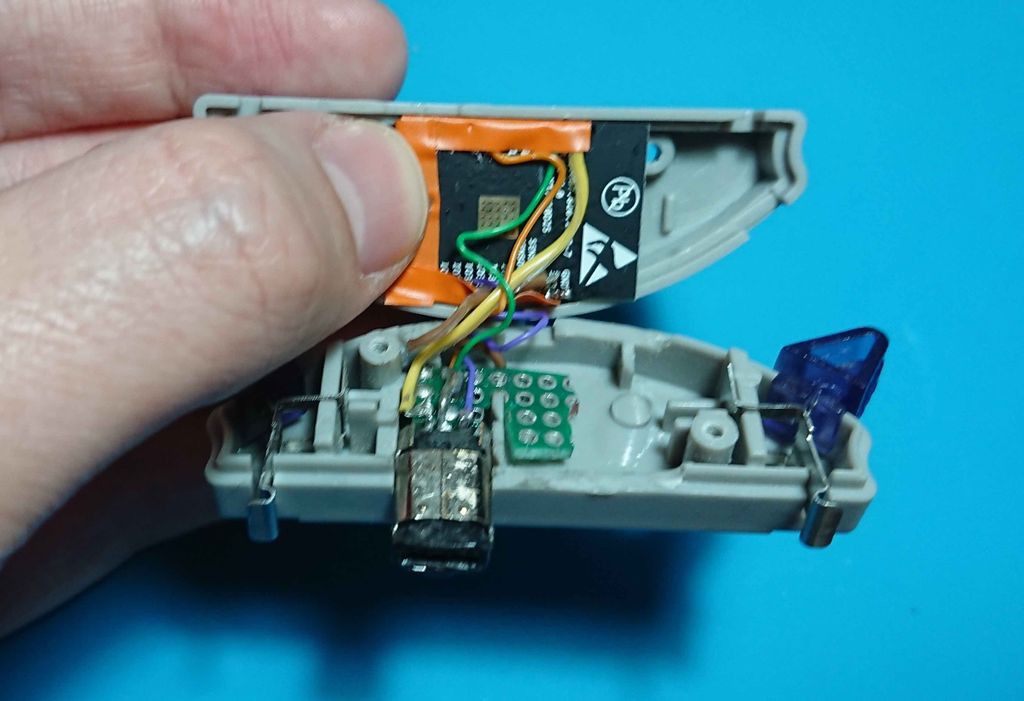
Put some electrical tap to the ESP32 pins so you avoid any short once it is closed. Place the pieces like the picture. The cut perfboard with the link connector in one side and the ESP32 on the other. Bring the two sides together bending the cables so the remain inside.
Put the two screws and you are ready to go!
 Shyri Villar

Discussions
Become a Hackaday.io Member
Create an account to leave a comment. Already have an account? Log In.