-
Using USB HID Reports to manipulate GPIO pins
01/02/2020 at 00:00 • 0 commentsOver the last several days I've spent some time trying to get a cheap eBay-sourced OLED I2C screen up and running using the SineStick. While I can clearly see it on the I2C bus, I have not been successful getting anything to show on the screen.
However, part of the project was figuring out how to toggle the screen #Reset line using a CP2112 GPIO pin. I suspect this may be a useful trick to others using this the CP2112 (or similar) chips, so I put together an example/proof-of-concept.
In you're interested, check out this projects file section for 'example_SineStick_LEDblink.py'!
-
Production file now available
09/02/2019 at 04:18 • 0 commentsIf you want to follow along at home, I've uploaded a zip file that has the Gerber files (board and paste stencil), bill of materials, and schematic.
All the parts should be available at Digikey, and the Gerber files should be readily accepted by OSHPark (that is where I got my PCBs).
Let me know if you build one!
-
Revision B - assembled and working!
09/02/2019 at 04:13 • 0 commentsWell, the activity LEDs don't work yet, but check this out:
[ 3490.443830] usb 3-1: new full-speed USB device number 5 using xhci_hcd
[ 3490.593313] usb 3-1: New USB device found, idVendor=10c4, idProduct=ea90, bcdDevice= 0.00
[ 3490.593317] usb 3-1: New USB device strings: Mfr=1, Product=2, SerialNumber=3
[ 3490.593320] usb 3-1: Product: CP2112 HID USB-to-SMBus Bridge
[ 3490.593323] usb 3-1: Manufacturer: Silicon Laboratories
[ 3490.593325] usb 3-1: SerialNumber: 00ACA028
[ 3490.661995] cp2112 0003:10C4:EA90.0002: hidraw1: USB HID v1.01 Device [Silicon Laboratories CP2112 HID USB-to-SMBus Bridge] on usb-0000:08:00.0-1/input0
[ 3490.716377] cp2112 0003:10C4:EA90.0002: Part Number: 0x0C Device Version: 0x03
Make sure you have i2c-tools installed via whatever package manager you prefer, then:
[user@localhost ~]$ i2cdetect -l
i2c-0    unknown       SMBus I801 adapter at 0400
[snip]
i2c-5    unknown       CP2112 SMBus Bridge on hidraw1
And then:
[user@localhost ~]$ sudo i2cdetect -y -r 5
     0  1  2  3  4  5  6  7  8  9  a  b  c  d  e  f
00:          -- -- -- -- -- -- -- -- -- -- -- -- --
10: -- -- -- -- -- -- -- -- -- -- -- -- -- -- -- --
20: -- -- -- -- -- -- -- -- -- -- -- -- -- -- -- --
30: -- -- -- -- -- -- -- -- -- -- -- -- -- -- -- --
40: -- -- -- -- -- -- -- -- -- -- -- -- -- -- -- --
50: -- -- -- -- -- 55 -- -- -- -- -- -- -- -- -- --
60: -- -- -- -- -- -- -- -- -- -- -- -- -- -- -- --
70: -- -- -- -- -- -- -- --
Address 0x55 should be the oscillator - the actual address depends on factory presets requested when ordered. Each preset is assigned a unique 6 digit code which is incorporated into the part number. I ordered from DIgikey (not directly from SiLabs) so it was unclear what the address would be.
If I understand the CP2112 docs correctly, the chip shouldn't show up during an i2cdetect scan. Clearly it's working (otherwise we won't be seeing anything at all) and the datasheet says it should be available at address 0x02.
I think the next goal should be a small/simple utility that just sets the output frequency.
-
It works! And new board revision.
08/19/2019 at 03:27 • 0 commentsI was using the end off an Amazon USB cable and it looks like the internal wire colors were swapped. Out of ideas last week, I swapped the data lines and the chip enumerated successfully!
Now that I knew that it worked, I figured it was a good time to do a board revision:
![]()
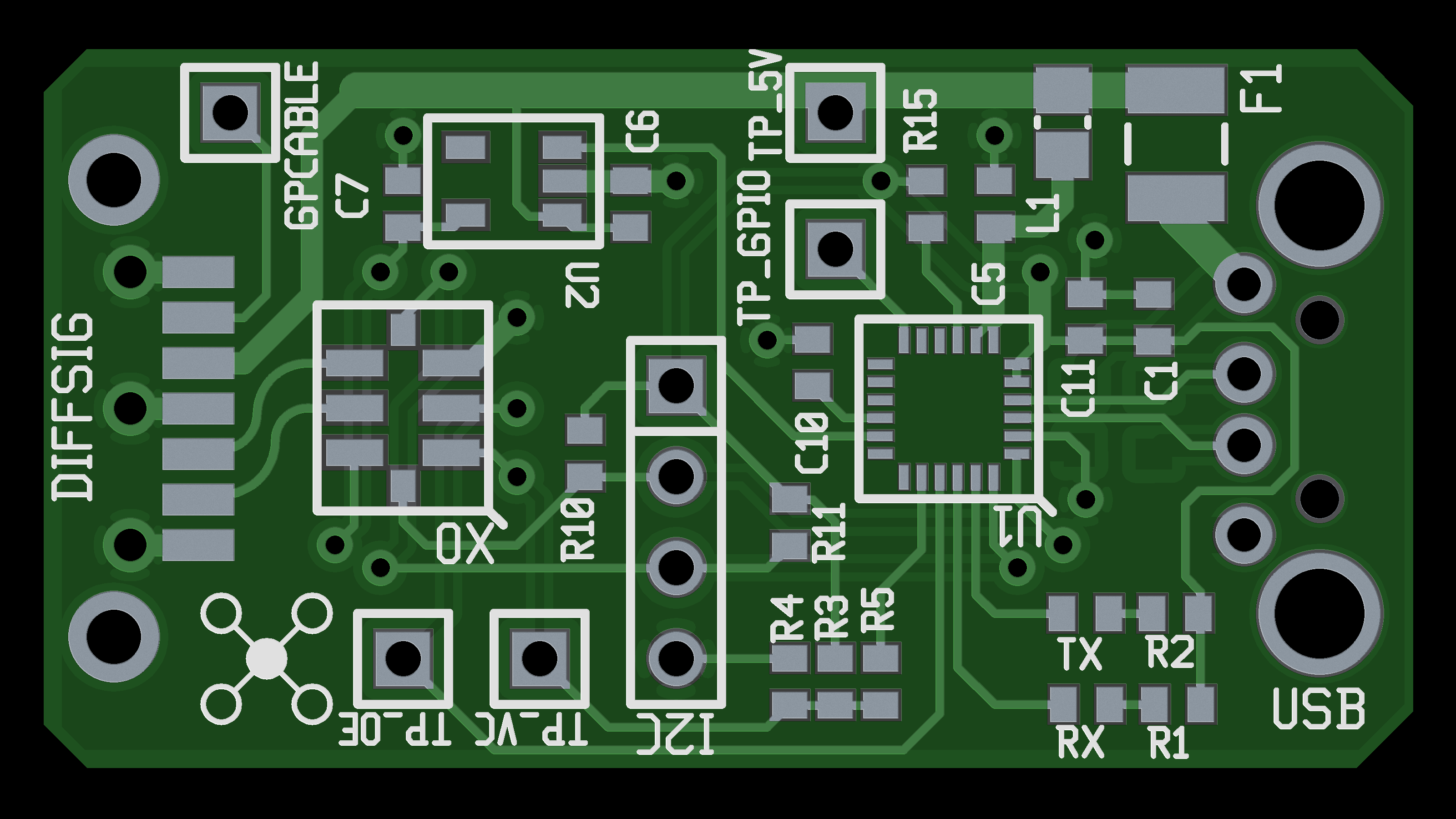
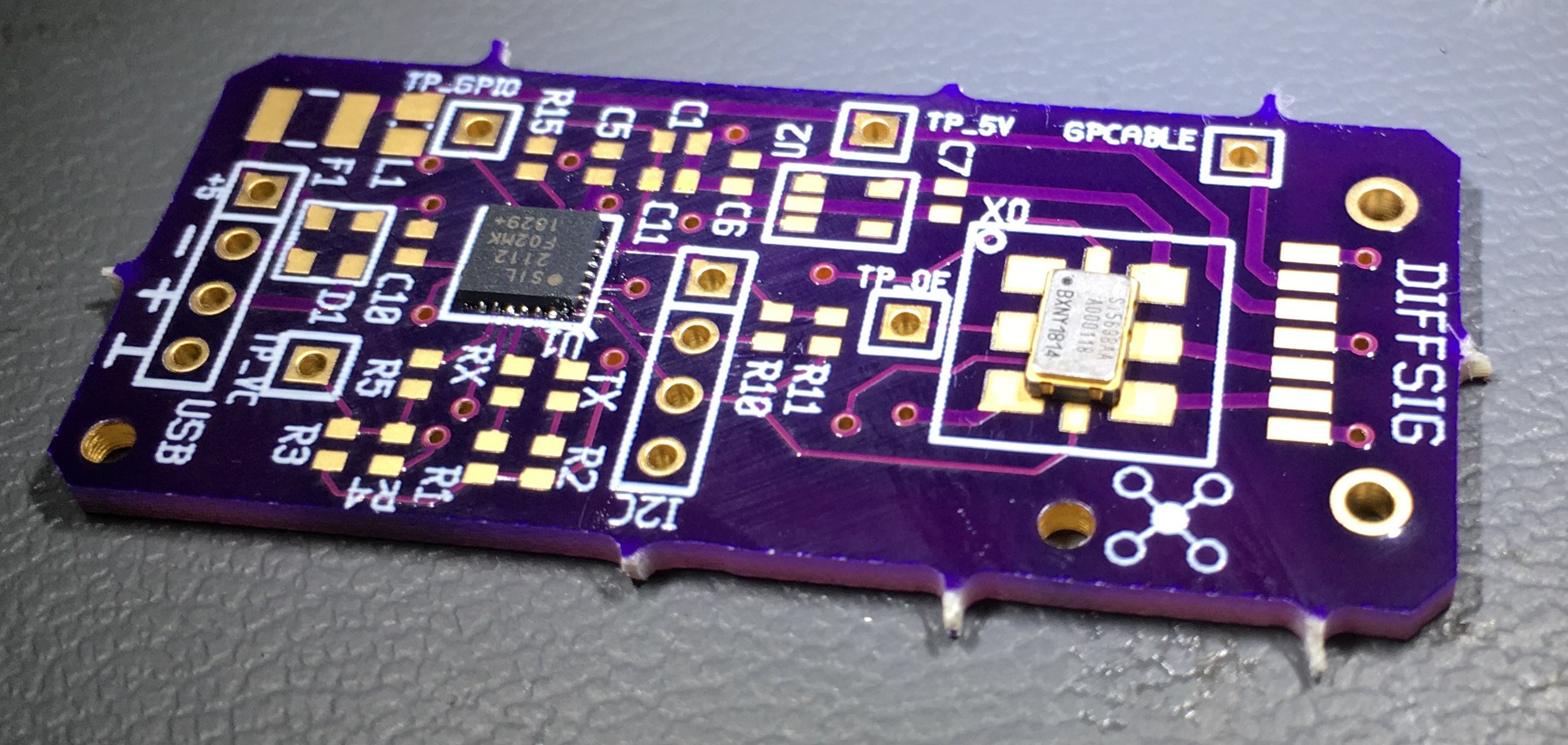
You might notice that the Rev B board is shorter than the Rev A board. I moved the TVS diode array to the opposite side - the wiring between it and the CP2112 was a tad frustrating and taking up a bunch of space. The XO footprint is the smaller 3.2 mm by 5 mm variant which should match the parts I have.
I also added a footprint for a PCB mount USB-A male connector. It's what I originally intended to do, and it's a lot cleaner than having the board at the end of a cable.
The only major circuit difference is that the SATA port pins have changed - check out the schematic in the gallery for details.
Boards have been ordered from OSH Park. I took down the link to the Rev A boards because they were obsolete - I wish there was a way to set up the sharing so it wouldn't expose the the raw Gerber files for download.
-
Problems and - well, just problems actually
08/15/2019 at 03:15 • 0 commentsSo, those oscillator parts? Over fifty bucks each. Not exactly pocket change. Unfortunately that invalidates the idea of this being the literal opposite of an RTL-SDR - I was aiming for in-the-cart cost no higher than $20.
This week I got some time on the microscope to assembled one of the boards. (Partially complete pictured below.)
Notice the XO and the HUEG footprint I placed. I thought I purchased the large variant of the XO part, but I guess not.
I think I can dead bug the XO, but held off at this point because I was pressed for time.
Sadly, the CP2112 chip doesn't enumerate when the board is plugged in. I've verified the USB cable wiring, removed the TVS diode, used the hot air station to reflow the solder/part, and verified that the system is seeing something - just can't get the chip to enumerate.
I'll start by pulling off everything non-critical until it works - or doesn't. I don't have an IR oven so there is a chance I toasted the chip when installing it.
Little less than a month left - onwards! -
"Where's the SMA connector?"
07/20/2019 at 16:14 • 0 commentsGood question.
Here is the problem: the Si569 only offers output up to 3 GHz when using a differential signal output (specifically LVPECL, LVDS, CML).
The majority of projects I've seen that us SiLabs oscillators use the CMOS output variants which supports single ended operation, but can only output a signal up to a few hundred MHz. (For this particular chip, only up to 250 MHz.)
(By the way, if you're interested in what all those output modes are, I highly recommend "Application Report SLLA120 - Interfacing Between LVPECL, VML, CML, and LVDS Levels" by Nick Holland at Texas Instruments.)
Here is the other problem: I'm not an actual RF engineer, I just play one on the Internet. I really don't know how to convert a high frequency differential signal into a single ended signal - or if I even should in this case.
I briefly looked into LVDS converter chips but couldn't find any that were obviously fast enough. At this point I think I'm supposed to use a balun or signal transformer of some sort but this is outside my experience right now.
So, what to do?
Make it somebody elses problem! :D
Okay, seriously though, I'm hoping I can provide the base unit and somebody with more experience than I can take this thing a step further and make a circuit that an antenna will attach to. To do that, though, I have to export the signal from the board. The the idea that the average hobbyist would be using these units, I needed something that easy to use, durable, inexpensive, widely available, and with the ability to support high speed differential signals.
I assume the majority of you are familiar with the famous Andrew "bunnie" Huang - I was reminded of his Novena oscilloscope project where he faced a similar problem. His solution was using common SATA cables - these hit all of the above requirements, so I stuck a SATA connector on the end of the SineStick.
I used B channel for the differential output of the Si569. I wanted to push I2C through channel A but there was no way to also push power as well (not enough pins). I decided having power at the other end the connector was more important than I2C control, so the A- channel is attached to the (fused) USB 5V rail. The otherwise unused A+ channel is broken out to a test point so end users can make use of it.
The only downside is nobody seems to make board mount SATA plugs - the cable ends. There are very short SATA cables available, however, so it's not a huge issue.
If this device catches on I hope to see an ecosystem of filters, amps, and antenna connector boards.
-
July 19, 2019 - Boards arrive tomorrow
07/20/2019 at 03:09 • 0 commentsLast week I oOrdered a set of boards from OSHPark, and a set of stencils from OSHstencils.
The boards should be here tomorrow but the stencils haven't arrived yet - which is odd. Usually they get here first.
After a quick visual inspection of the boards, I'll order the parts. Earliest they'll get here is Tuesday morning.
 Carbon
