Andrey V
-
My converters for MOTORSPORT
09/05/2019 at 12:28 • 0 comments![]()
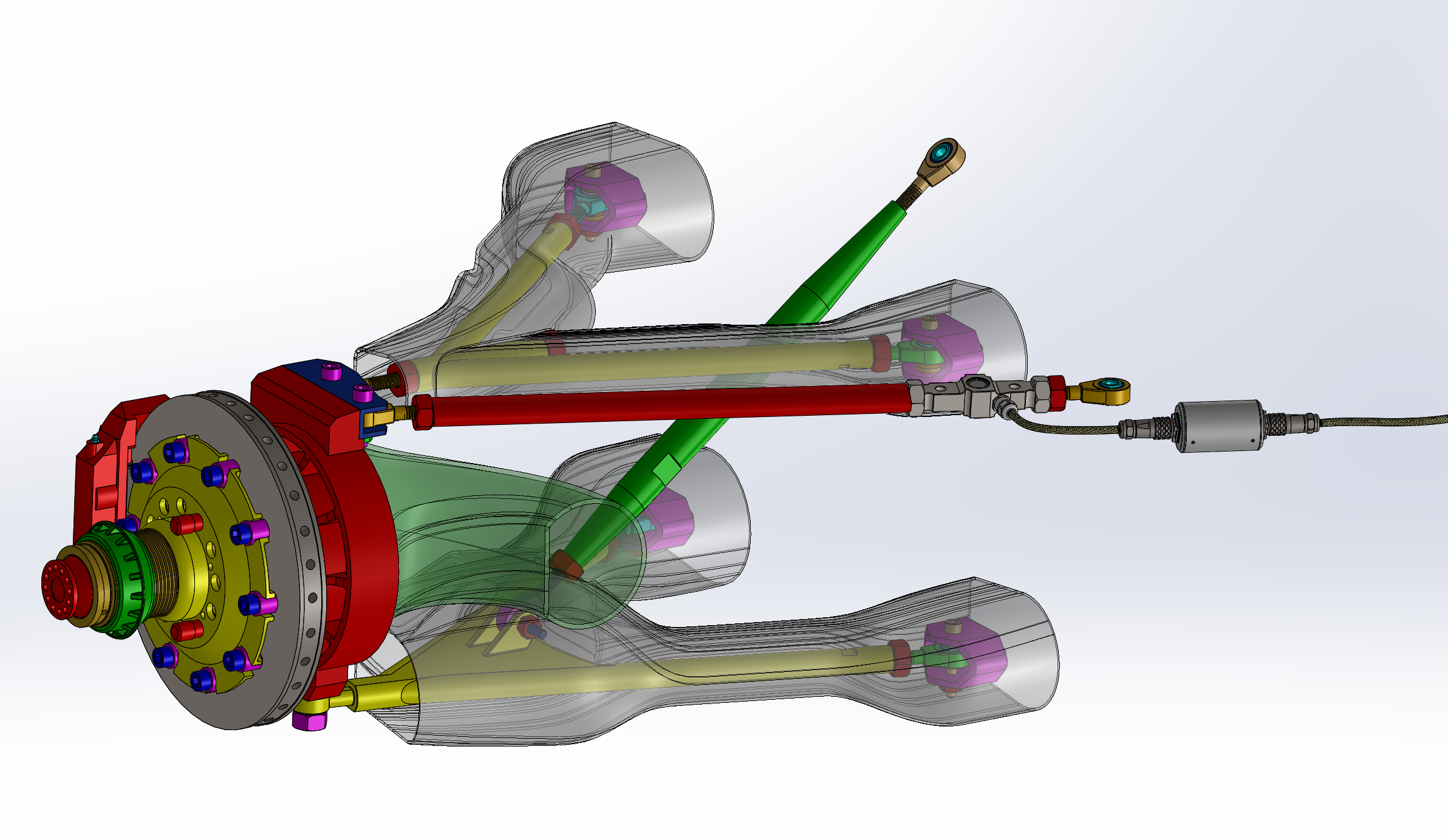
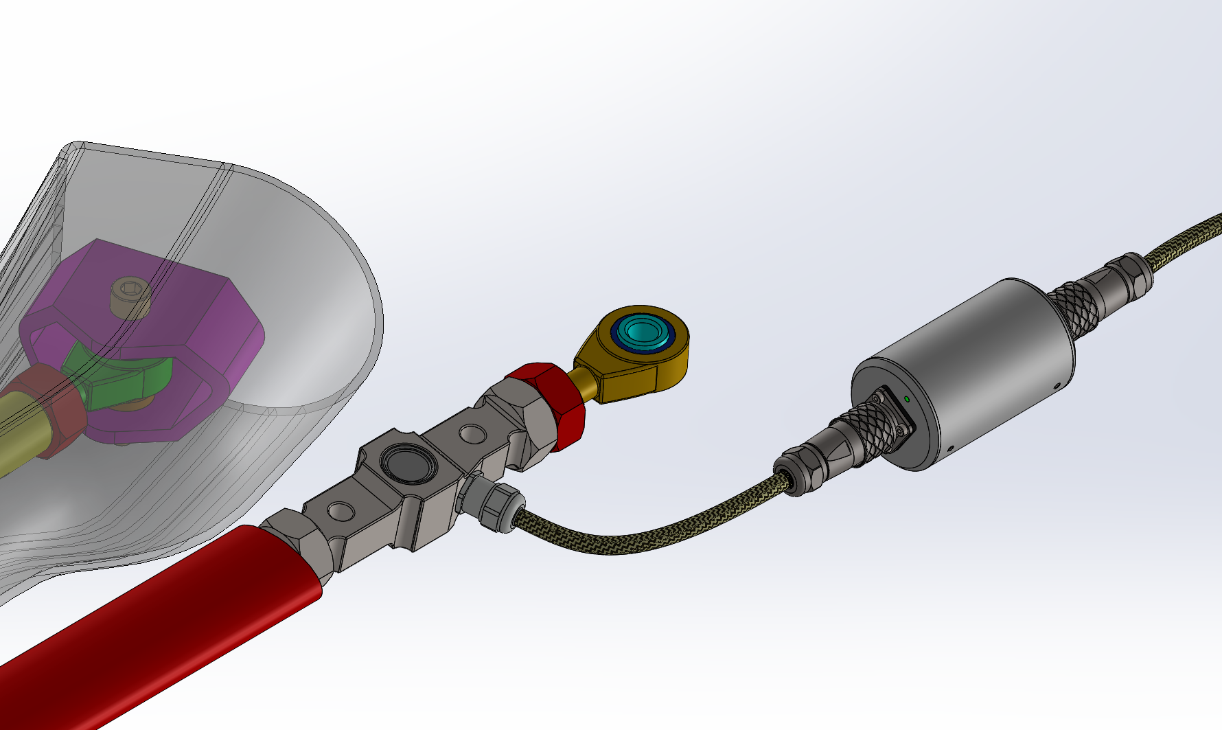
Some time ago I did a presentation about load cells used for interactive suspension loads measurements. I showed it three times and haven't had any feedback. The idea is simple:
![]()
But today I received a letter from one Motorsport team about cooperation ability in the field of suspension test and measurements. It's very low profit project, but I think life is not only about money.
This project has some challenges. At first, I need custom load cells to install if directly in suspension. I have some thoughts about it and I filed a patent application (I will publish it if I will get patent pending).
The load cell must be from titanium alloy to minimize weight. Also, it must have a specific form.
Also, I will need to change PHY and protocol from RS485 and modbus to CAN (for direct connection to the car) and Serial (for using with the radio transmitter). And make some more minor changes.
---------- more ----------Actually, I like motorsport, some years ago I drove motorbike like crazy(now I understand how dangerous was it). Also, I traveled a lot on motorbike around Europe and Asia. So I glad to participate in motorsport challenge with my humble knowledge.
-
PRELIMINARY TEMPERATURE DRIFT TEST
08/29/2019 at 07:52 • 0 commentsYesterday I did preliminary load cell temperature drift test.
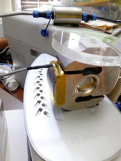
Here my test setup:
![]()
I understand it's not so accurate setup for measurements(I need thermal chamber for accurate measurements) , but let's look on the results:
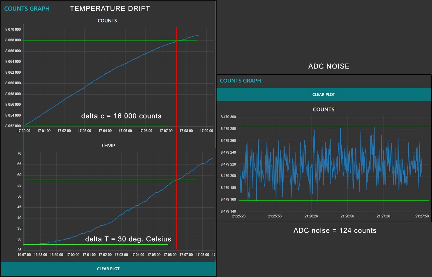
![]() ---------- more ----------
---------- more ----------As you can see I have 16000 / 30 = 533 counts temperature drift for 1 degree Celsius. It's more than 4 times higher than noise, and it's unacceptable for accurate measurement.
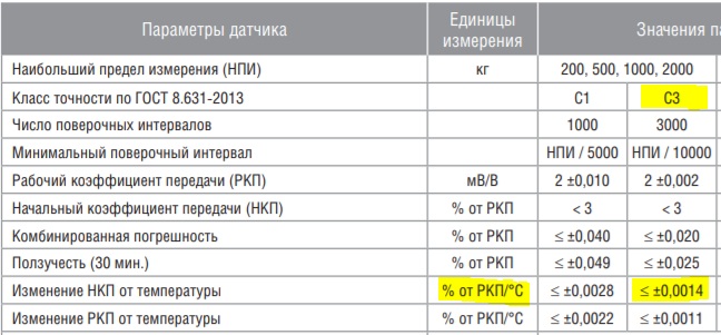
I use expensive hi-class (C3) load cell. Let's calculate how the load cell meets specifications.
![]()
C3 - accuracy class
Temperature effect on zero balance TKzero must be less or equal +//0.0014% for 1 degree Celsius from the full scale.
My ADC has 24bit resolution, so the number of counts = 2^24 = 16 777 216 and calibrated exactly for this load cell full scale
Temperature drift = 533 counts
So:
TKo = 533 / 16 777 216 / 2 * 100 = 0.0016%
It's slightly higher then I see in the specification.
Let's calculate temperature drift error in grams. I use 200kg load cell which works in both directions (tension and compression) so it has 400kg full scale.
TKo = 533 / 16 777 216 * 400 000 = 12.7 gram/1 degree Celsium.
It's significant error in measurements. That's why I did all this project!
Why it's significant error? Because the standard deviation with filtering (20 values mean) only 0.65 gram for 400 000 gram full scale load cell.
![]()
Sensitivity balance of the load cell also have temperature drift (TKc - Temperature effect on sensitivity balance).
I will try to test it next time.
-
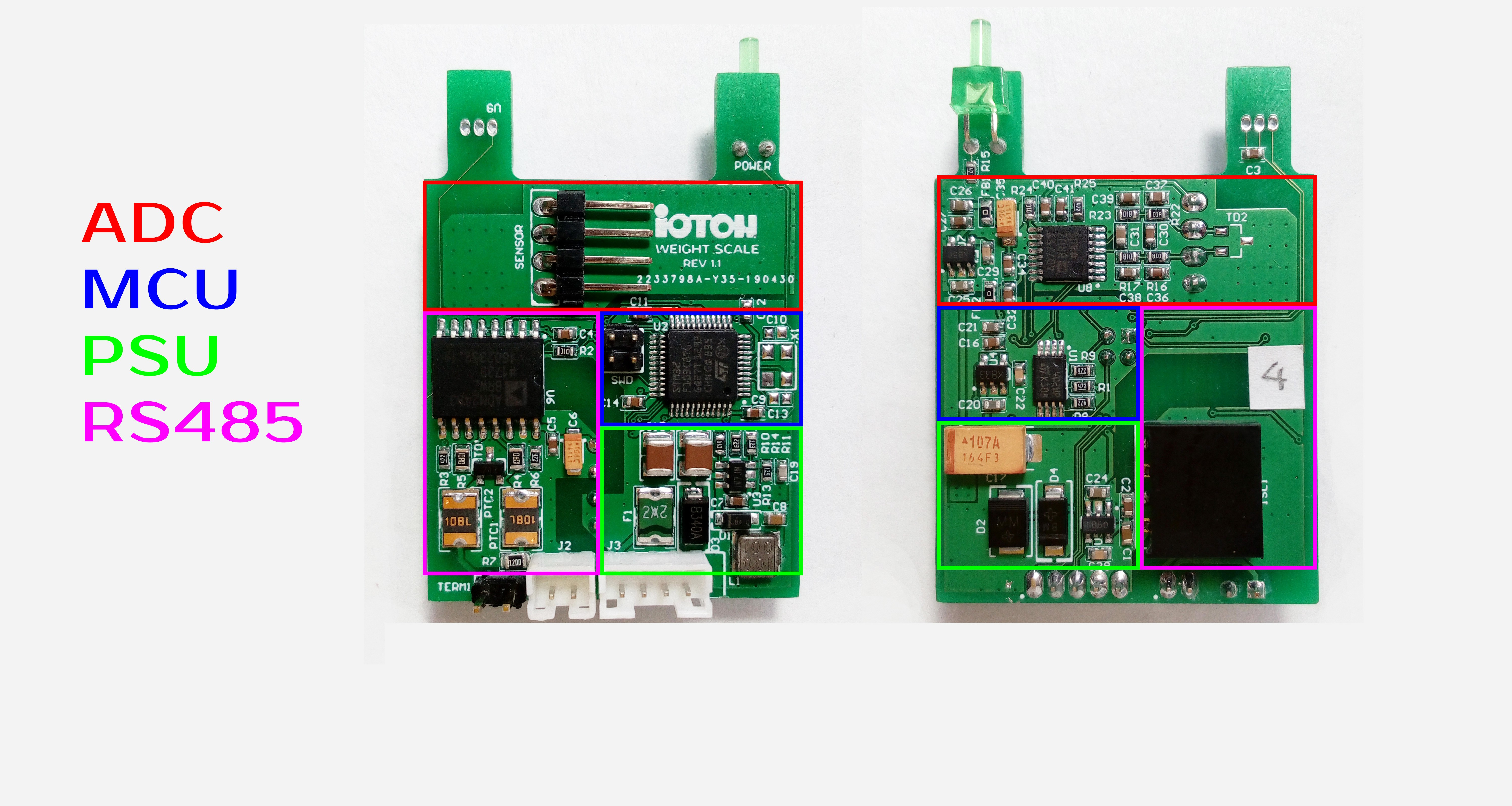
PCB zones
08/27/2019 at 15:56 • 0 commentsWhen I'm developing PCB, I decided to split the PCB into 4 main zones, absolutely symmetrical from both sides:
![]()
It was a little bit challenging to provide proper grounding w/o undesirable current paths. I did some minor mistakes with the grounding in REV 1.0 but I think I fixed it all in REV 1.1.
Also, the additional spacing between unisolated GND and isolated GND was added.
I used 0603 parts (minimum size) for hand mount ability. Unmounted parts - temperature sensor(U9).
-
It's time to swim.
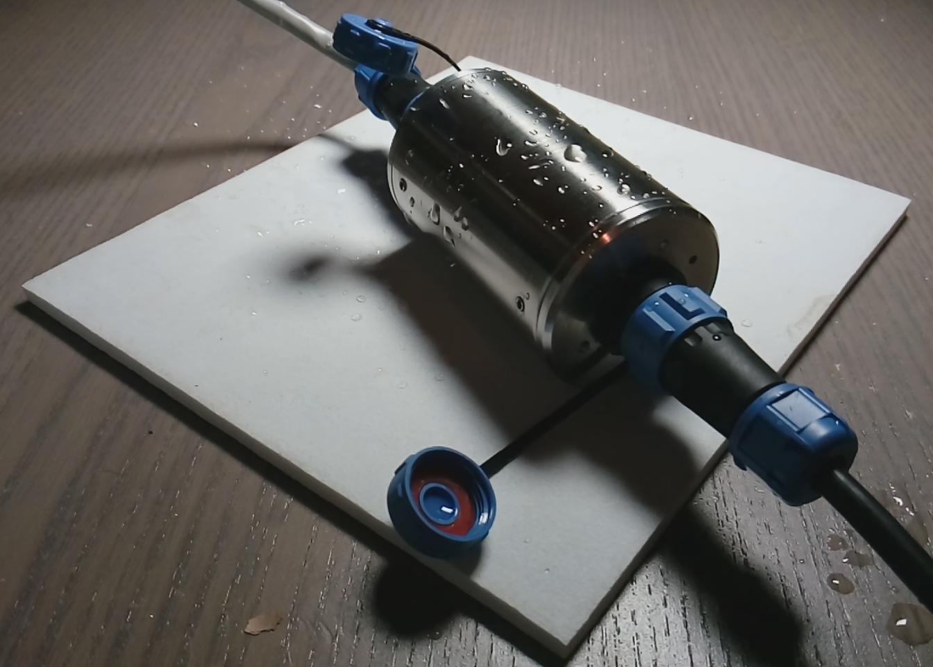
08/21/2019 at 17:53 • 0 commentsFor outdoor usage, I need to make some tests.
At first, my device must take a bath.
I can't do complete IP68 test right now, but I will do it later.
![]()
![]()
I think I leave it in the glass for one night with logging sensor data.
-
ADC NOISE & SENSOR NOISE
08/20/2019 at 18:58 • 0 commentsSome measurement of sensor and ADC noise.
I wrote a simple software to measure sensor noise and get the noise-free count.
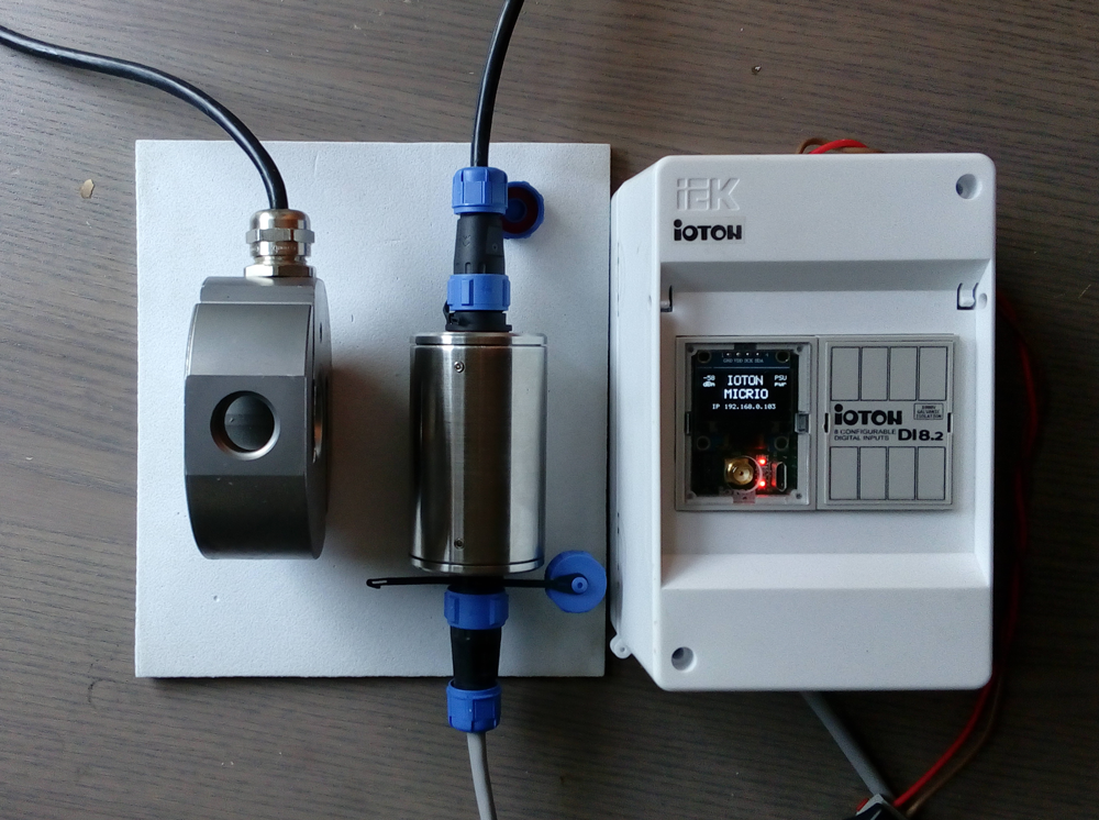
Test setup:
![]()
Left to right: 0.2ton Load cell, my Load cell - Modbus interface, IOTON MICRIO MPU & DI8 input module.
500 counts noise video:
As you can see, I have around 120 counts of noise Peak-to-Peak.
Lets calculate the counts... 24bit = 2^24 = 16 177 216 counts. Noise of my system = 120 counts. So I will have 16 177 216 / 120 = 134810 noise free counts, it's around 17 bits. Not so bad.
For 200 kg load cell (actually it's 400 kg load cell, because 200kg for compression and 200 kg for tension) I will have an accuracy of around 200 000 * 2 / 134810 = 3 gram.
-
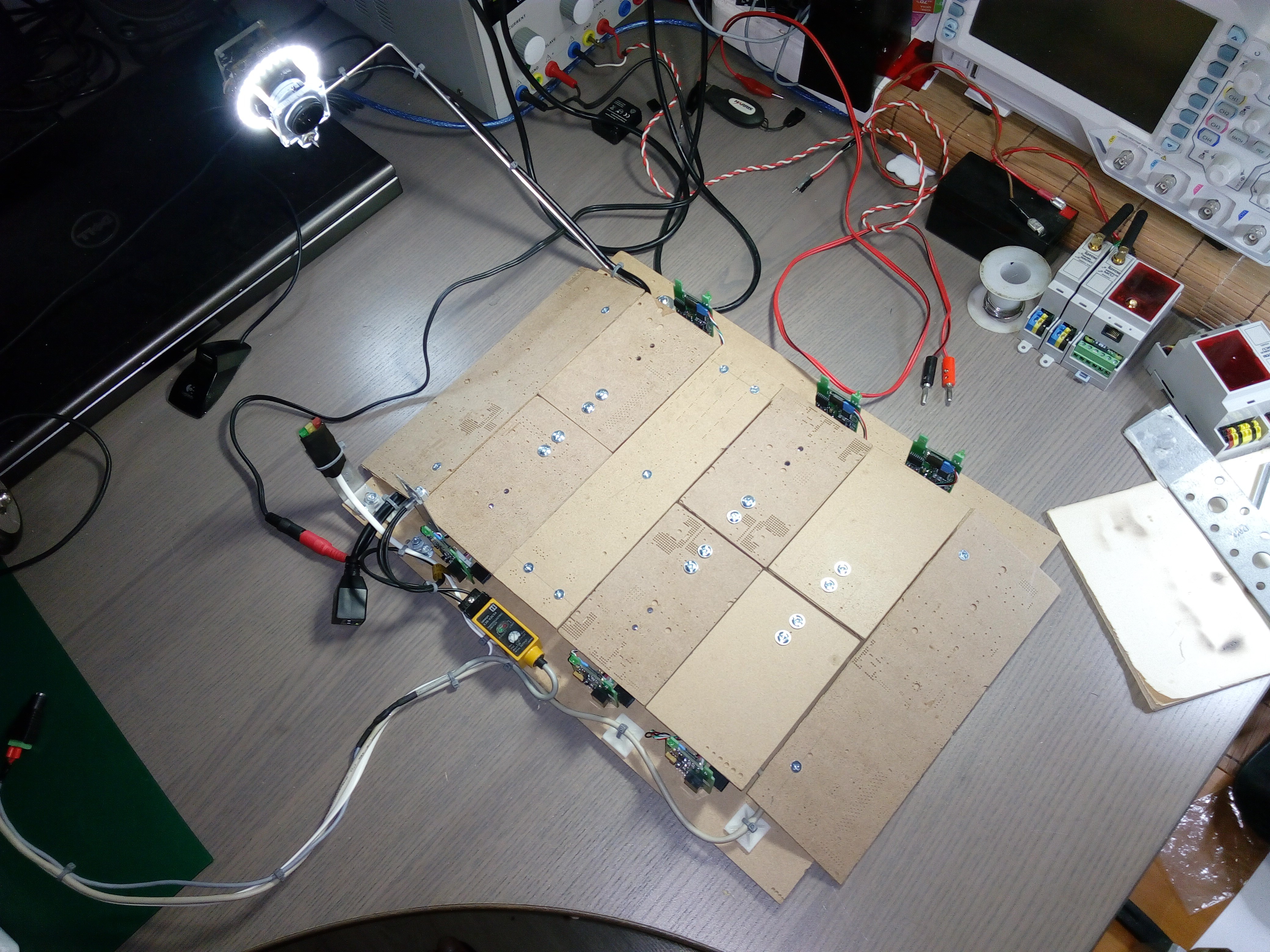
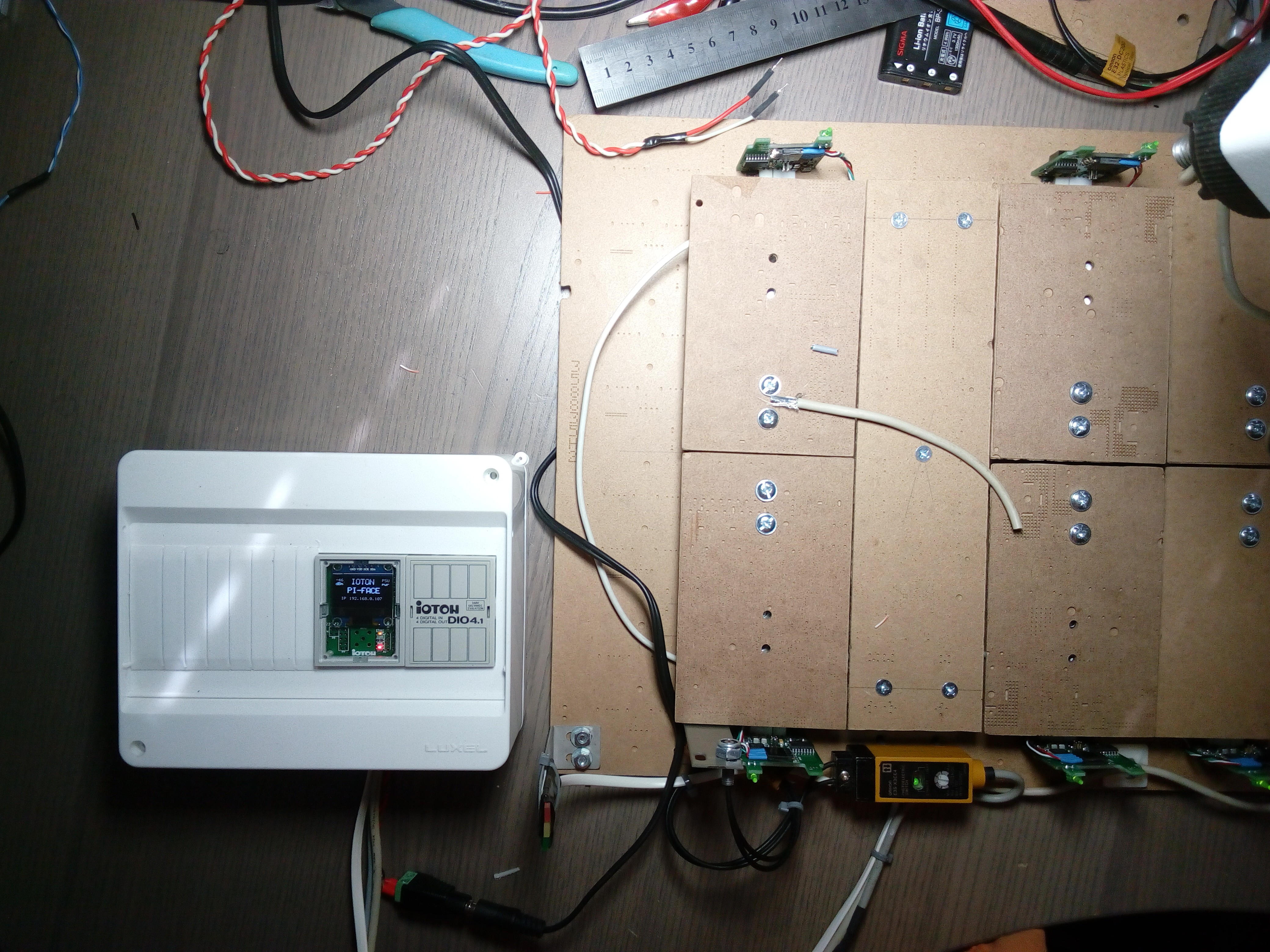
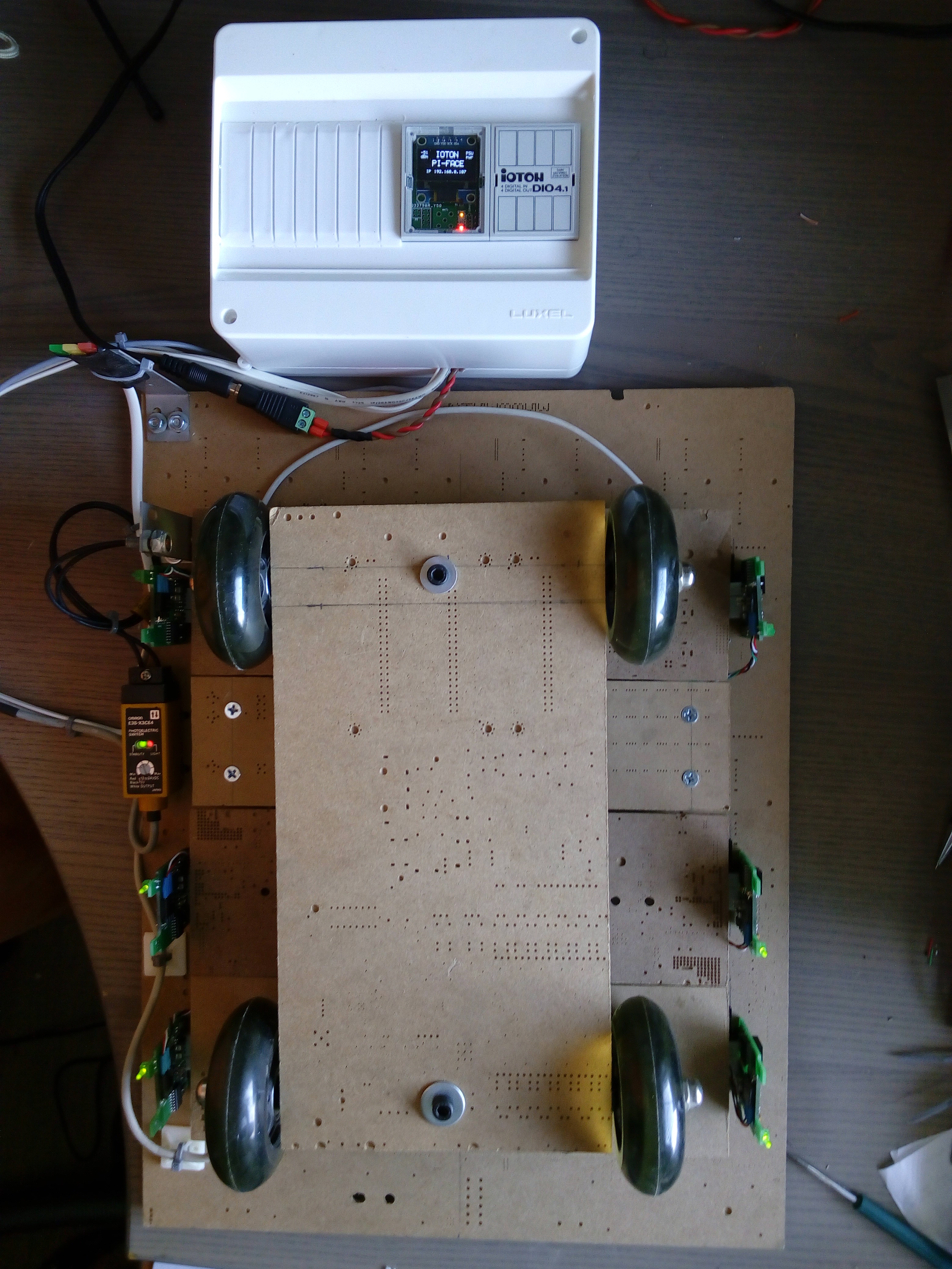
TEST SETUP hardware completed.
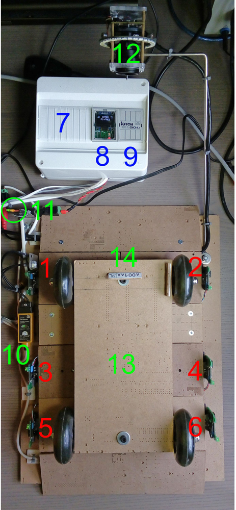
08/19/2019 at 11:19 • 0 comments1, 2, 3, 4, 5, 6. Independent weight scales. Each consists of the load cell and Load cell - Modbus converter (PCB w/o housing)
7. DIN enclosure with Raspberry PI3 B+ inside.
8. IOTON PI-FACE (my interface for Raspberry PI with RS485, RTC, UPS, power controller, WATCHDOG, GPIO connector for modules e.t.c.)
9. IOTON DIO4.1 (my universal isolated I/O module)
10. OMRON E3S-X3CE4 (photoelectric switch)
11. LED traffic light for the driver.
12. IP camera for the license plate recognition.
13. Truck model (I need to add one more axle)
14. Interchangeable license plate model.![]()
-
TEST SETUP. UI minor modification.
08/18/2019 at 19:41 • 0 commentsAdded:
- Total load gauge.
- Traffic light.
- Dynamic change for gauge max load and color signalization.
![]()
-
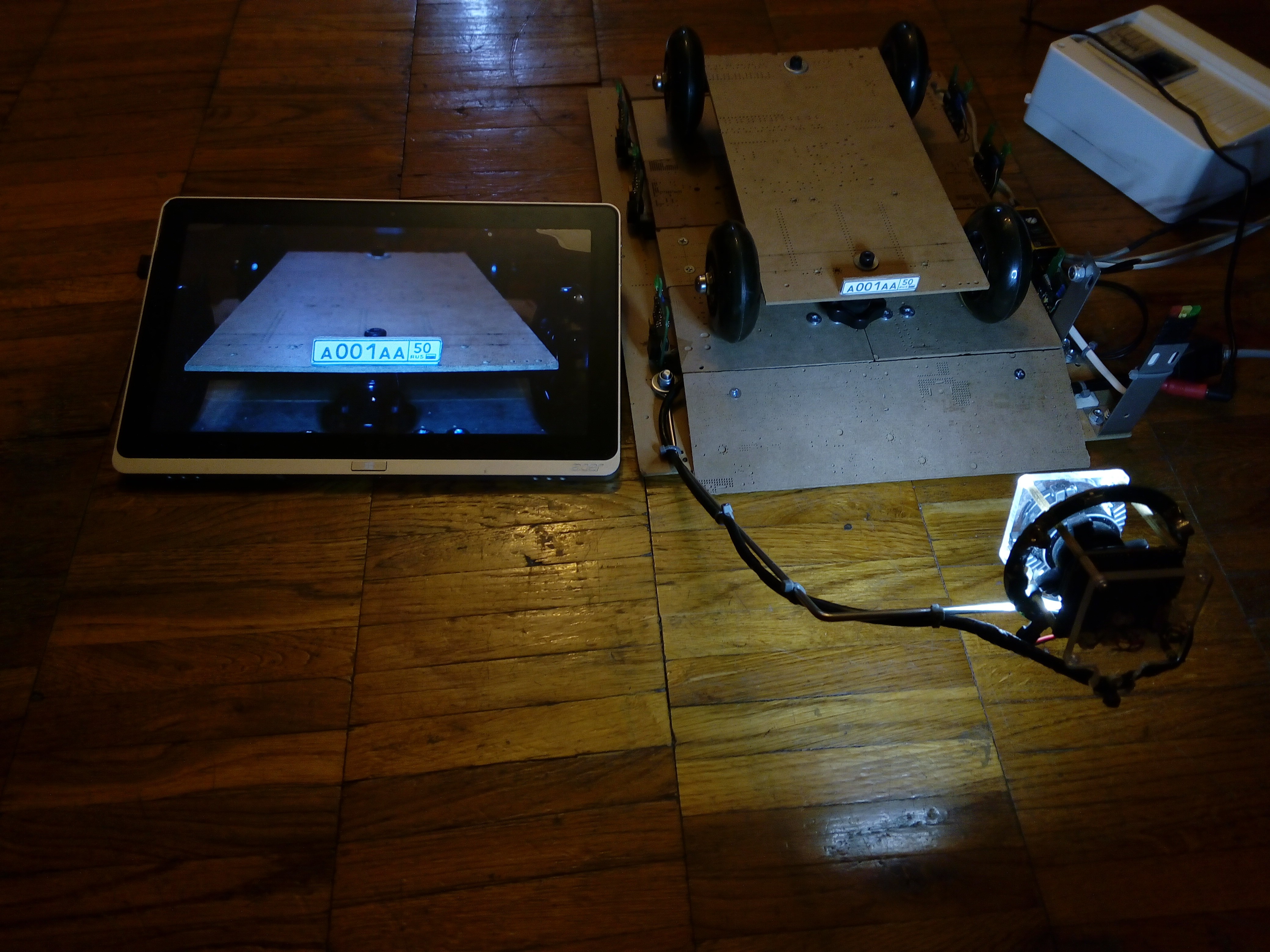
TEST SETUP IP camera for license plate recognition.
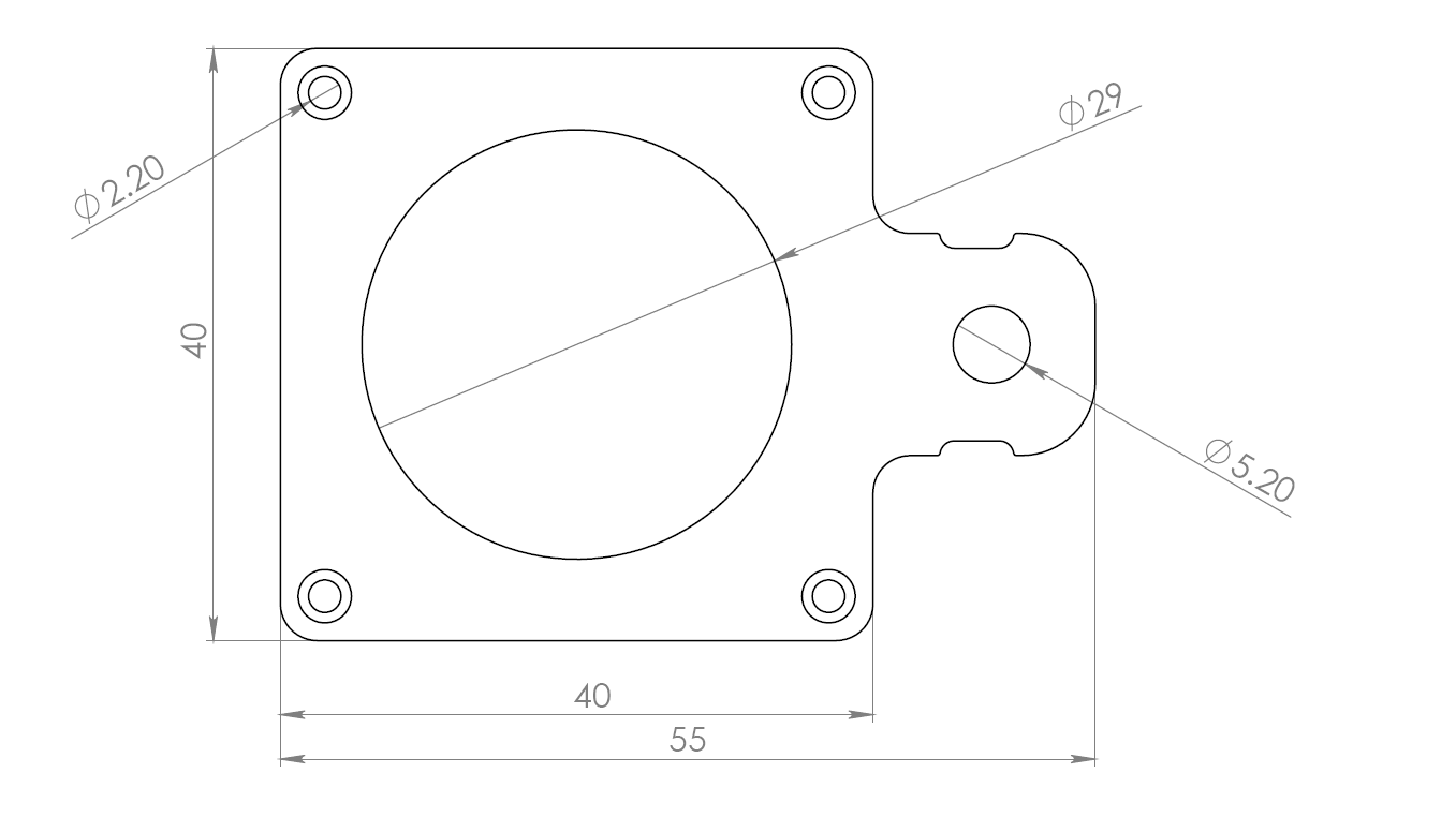
08/17/2019 at 13:23 • 1 commentJust finished IP camera mount for license plate recognition.
I used IP camera module, therefore I need some mounts for it. So I did it on my home CNC from the acrylic glass.
The mount drawing:
![]()
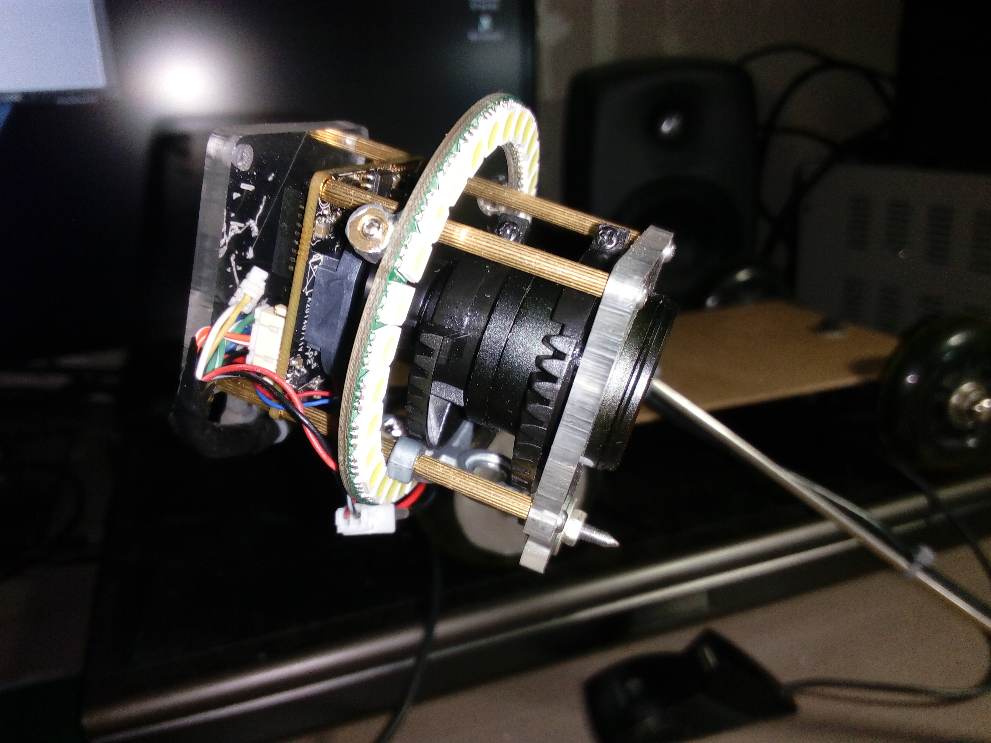
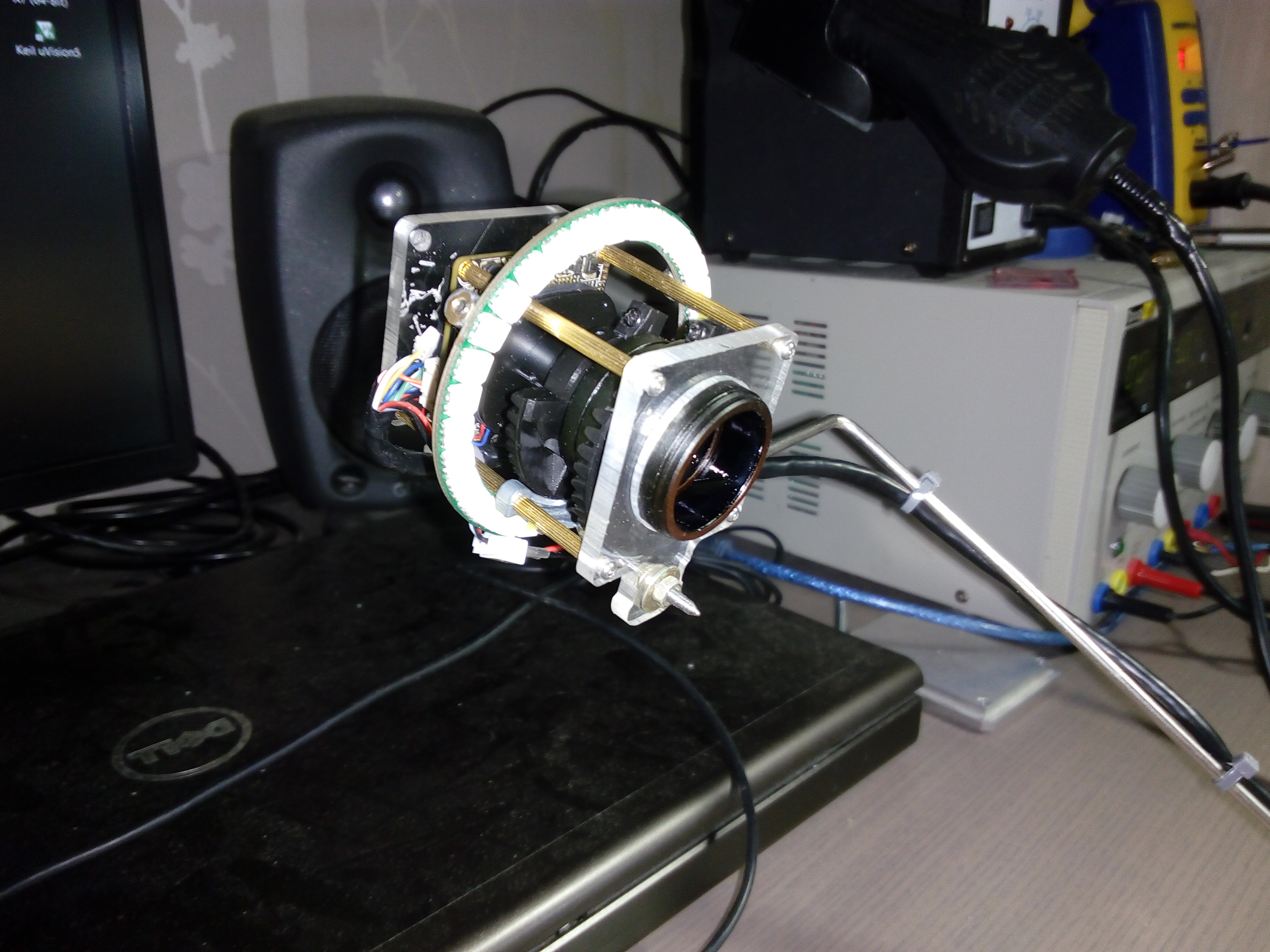
Mounted camera:
![]() ---------- more ----------
---------- more ----------(i used Microscope LED Light from my other project https://hackaday.io/project/166605-worlds-smallest-ring-microscope-light)
![]()
So, now my test setup looks like this:
![]()
![]()
Camera view(on tablet):
![]()
-
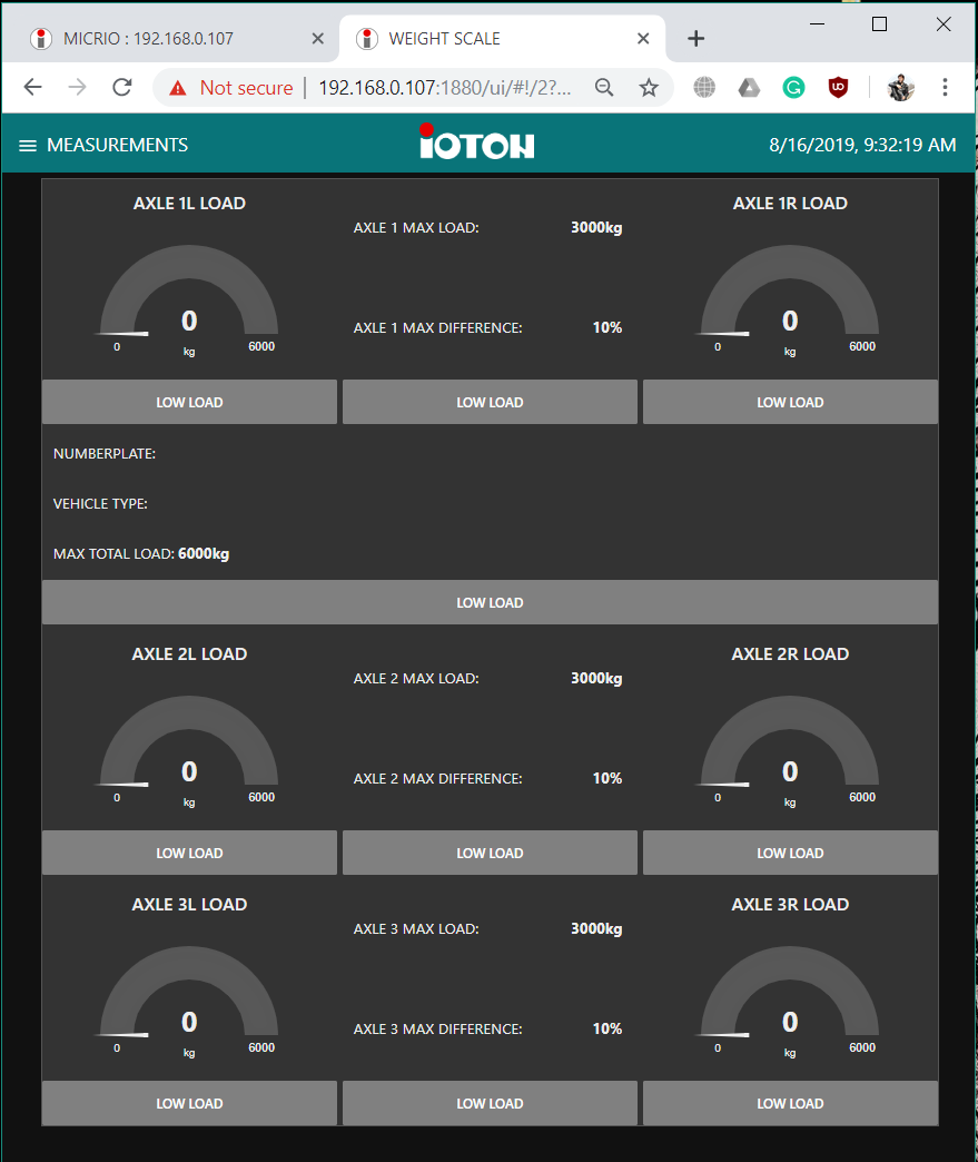
UI for TEST SETUP
08/16/2019 at 08:53 • 1 commentPreliminary version of UI for the test setup done.
It takes more time then I expected (around 14 hours).
It looks ugly, but I think functional enough.
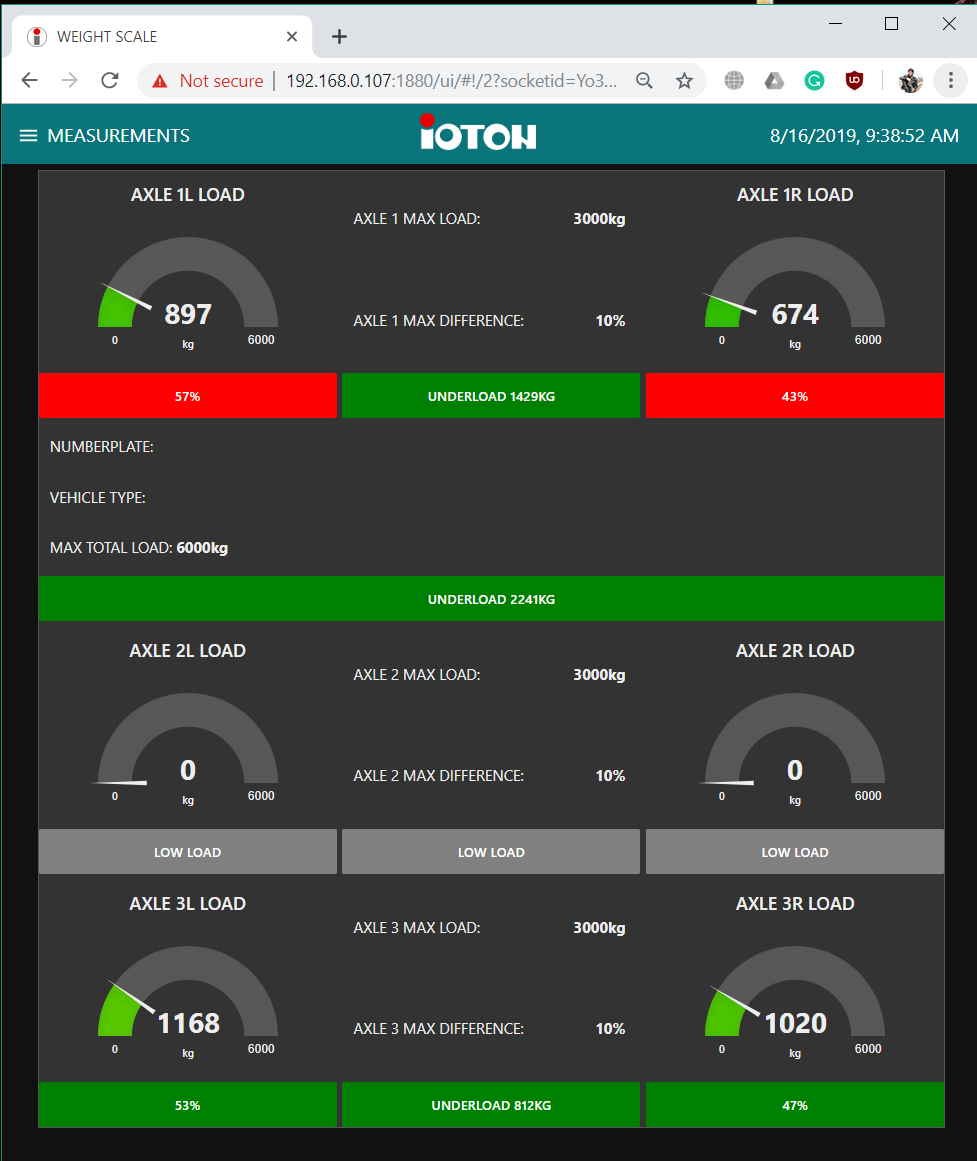
Measurement tab:
- Load gauge for each truck wheel
- Total truck load
- Overload/underload data and signalization for each axle.
- Max load field for each axle (kg)
- Load difference field for each axle (%)
- Load difference error indicator for each wheel
- Numberplate/ Vehicle type - for use with numberplate recognition system and vehicles database.
Unloaded:
![]() ---------- more ----------
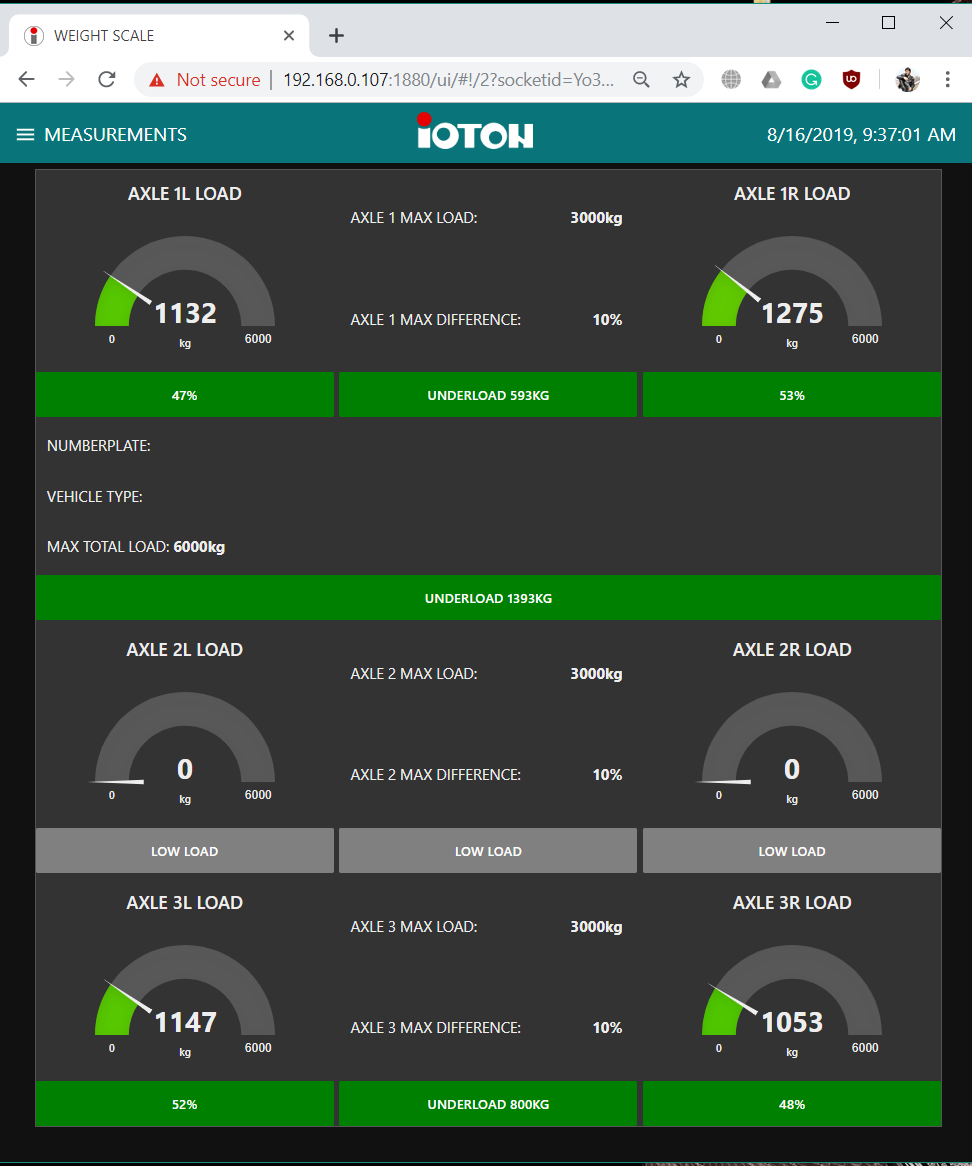
---------- more ----------Loaded:
![]()
With load errors(first axle load difference error, difference more than 10%):
![]()
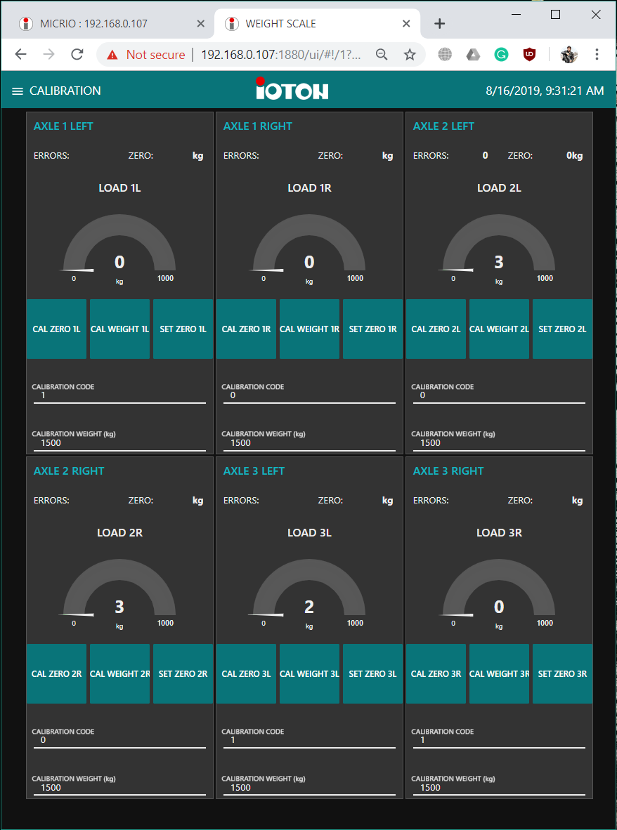
Calibration tab
For each Load cell - Modbus interface:
- CALIBRATION CODE field (cal. code is different for each Load cell - Modbus interface to protect from unexpected calibration)
- CALIBRATION WEIGHT field (you need to type calibration load weight in this field)
- Button to calibrate on zero load
- Button to calibrate on test load
- Button to set zero
- Gauge
- Sensor error indicator.
- Zero point indicator
![]()
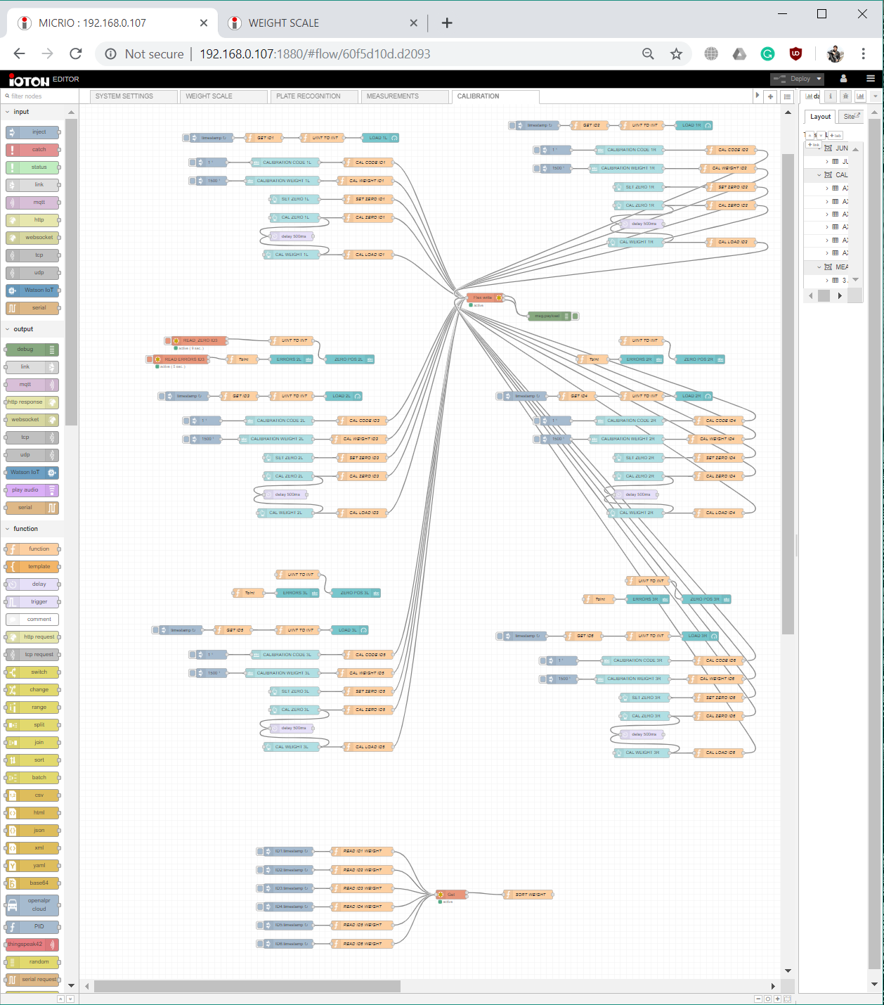
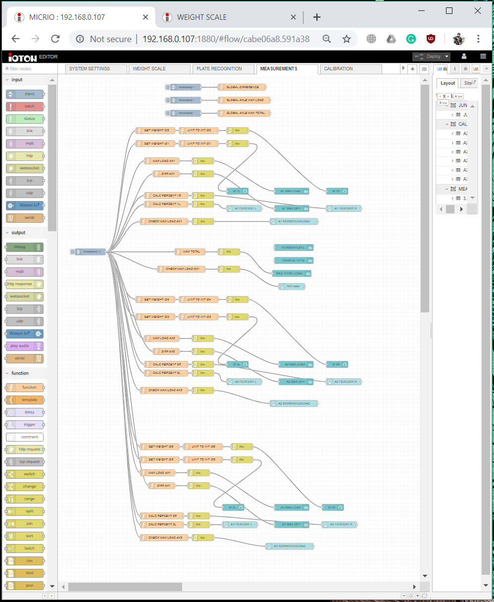
In editor it looks like this:
![]()
![]()
-
TEST SETUP. SCHEMATIC AND WIRING.
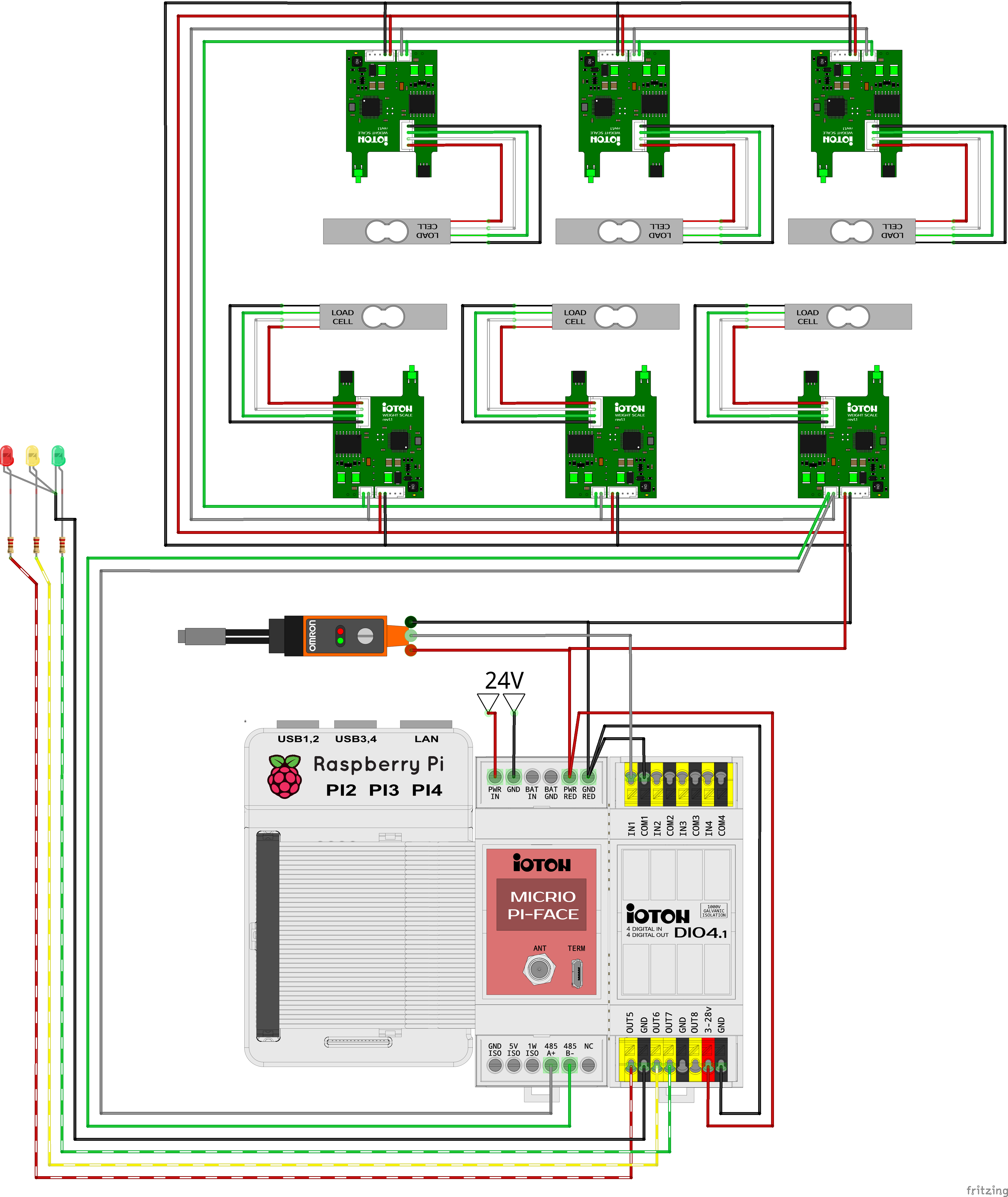
08/15/2019 at 07:13 • 1 commentSCHEMATIC
The schematic of my test setup is quite simple:
![]()
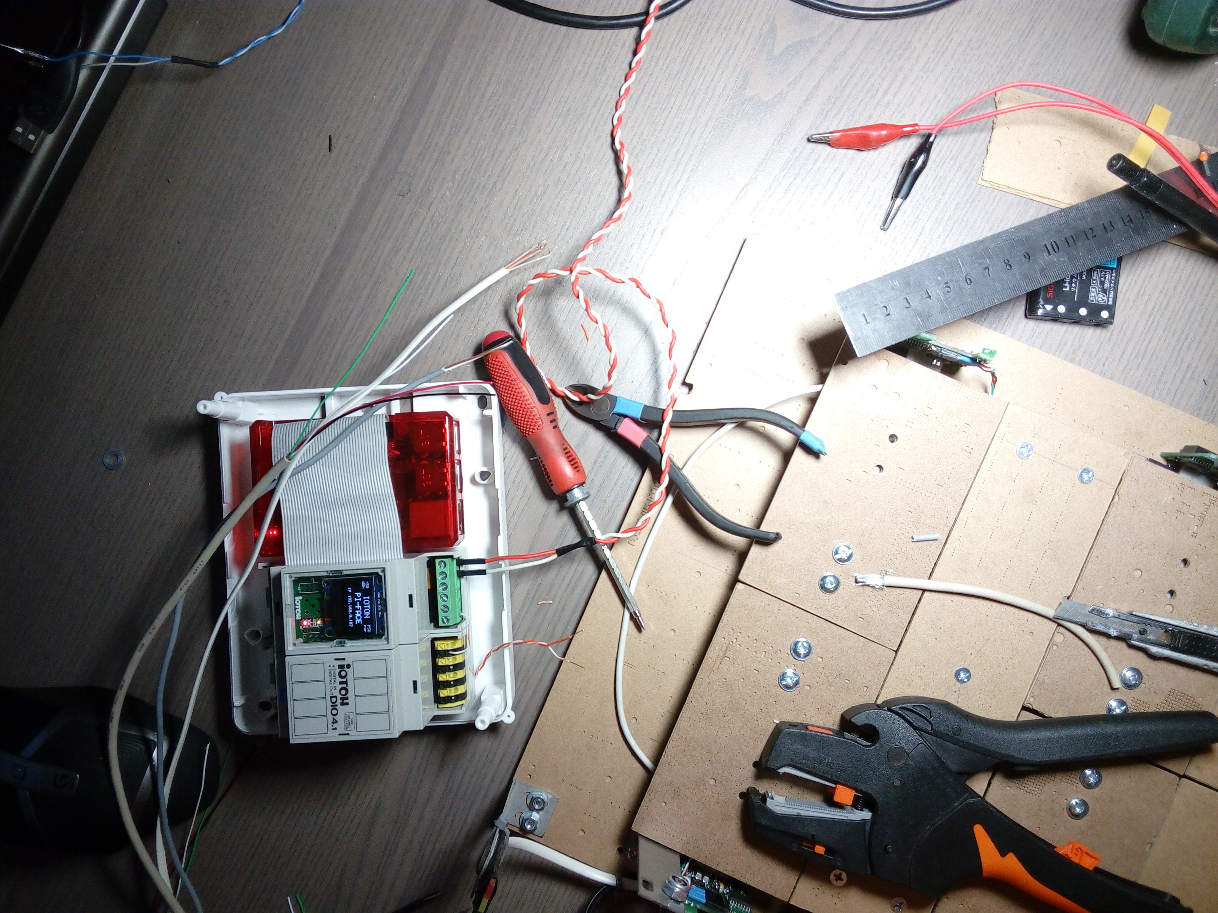
WIRING
It's also simple, I did it in around 30 minutes. It's no problem to connect cables to the powered device, it's only 24V and has protection and galvanic isolation for any inputs, outputs and data lines (like RS485 PHY).
---------- more ----------Cables connection:
![]()
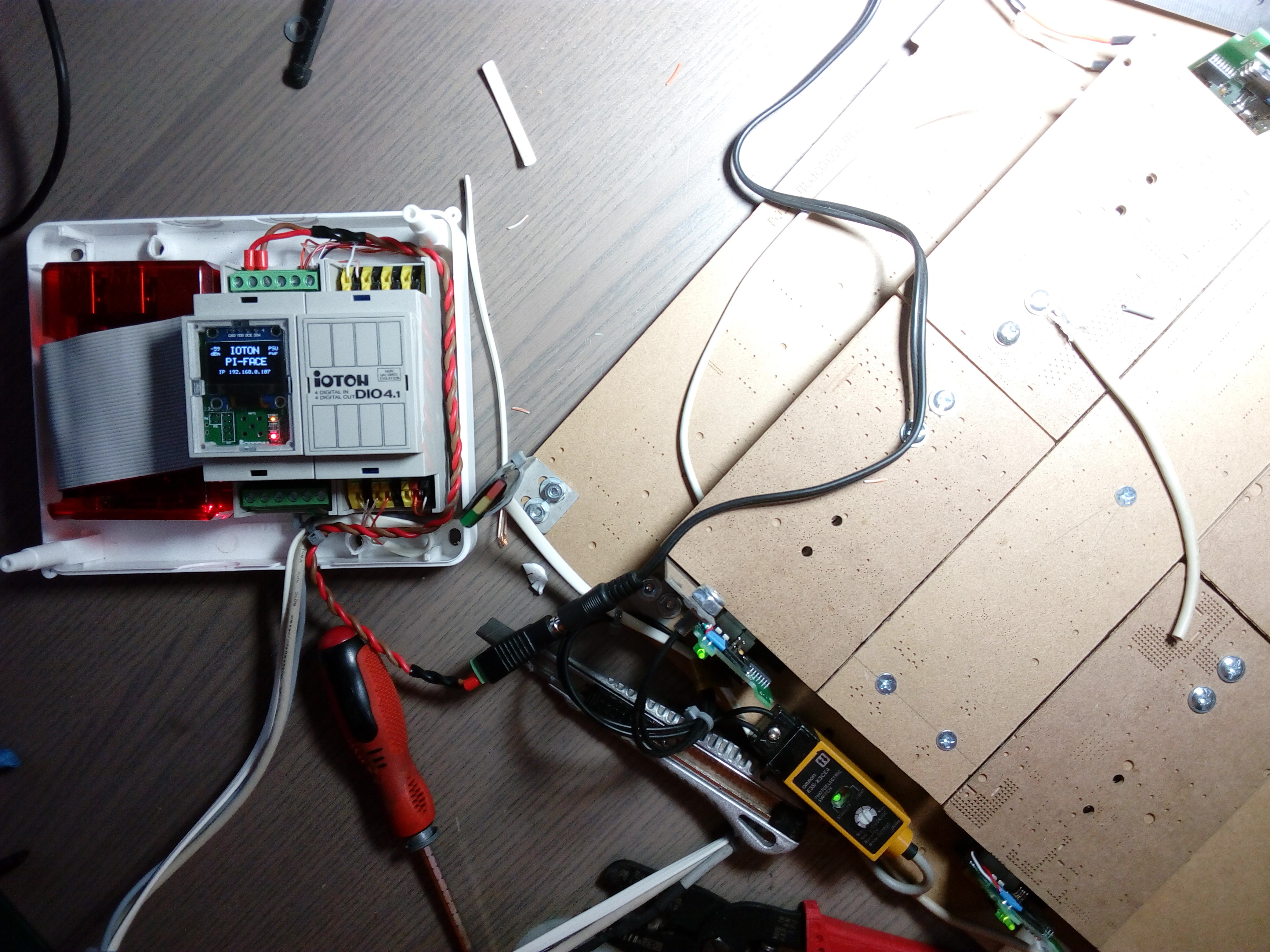
![]()
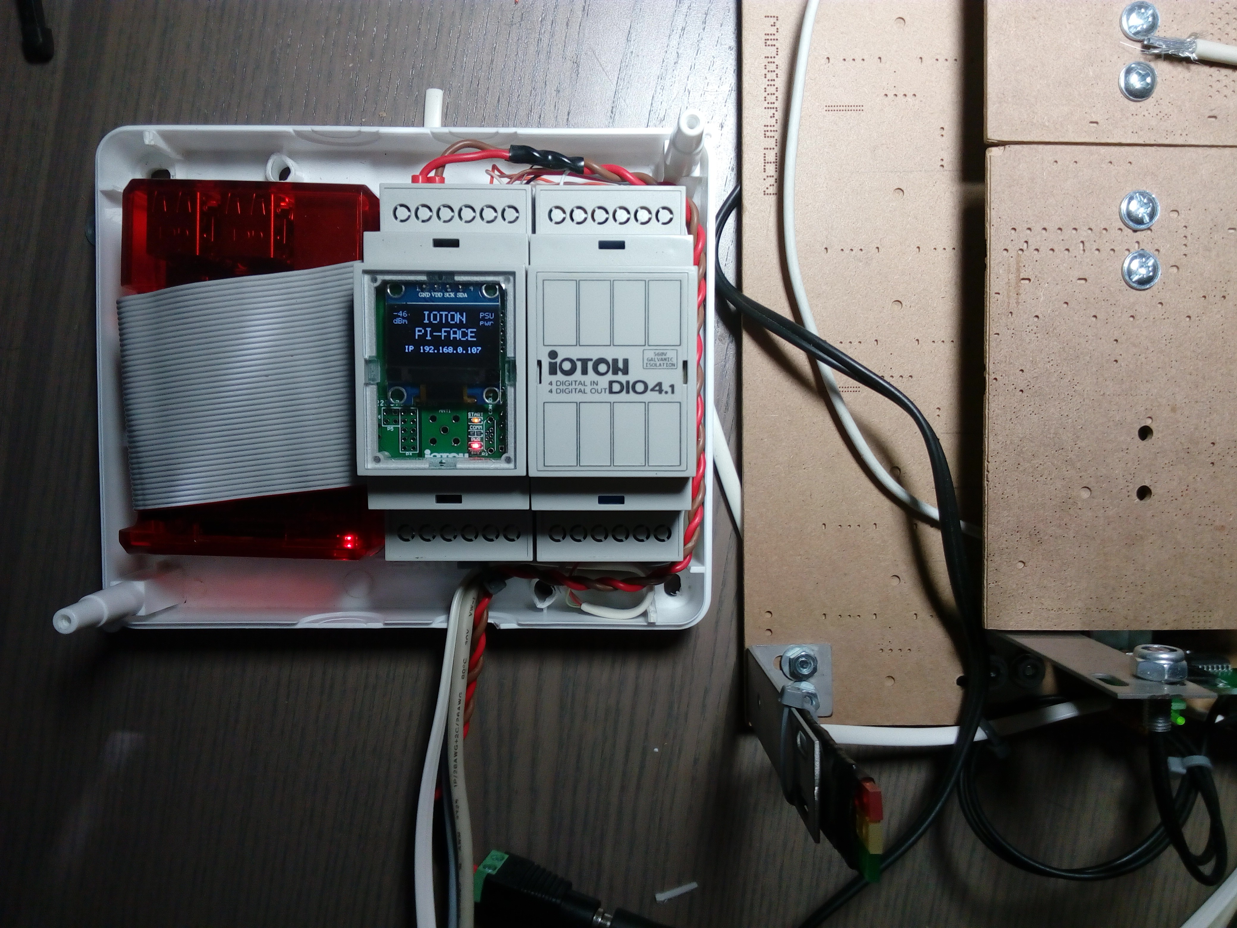
Put covers in place:
![]()
Ready setup looks like this:
![]()
![]()
Now it's time to create a user interface and do some programming.....
LOAD CELL to MODBUS
It's not a toy! It's the device for using in industrial weight measurement systems for trucks, trains, and conveyors.