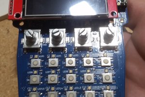
The game is centered around an XMega32E5 controller. This controller is nice because it has a 12 bit DAC and an EDMA engine, which are really easy to use as a digital audio playback system (see also my GPS Talking Clock project). The controller doesn't have nearly enough flash space for audio samples, so to hold them, there is an SPI flash chip. The flash chip has a FAT disk image in it with the audio sample files. There are also 4 buttons and 4 3-color LEDs. The LEDs are in a matrix, where the common anodes are selected by one set of 4 bits and the color cathodes are selected by another 3 bits. There are MOSFET drivers for each to protect the controller. The anodes have pull-downs on them to cut down on ghosting.
The SPI flash chip wiring is fairly perfunctory. It's the one SPI peripheral on the board, so it just gets all 4 of the SPI wires sent directly to it, along with 3.3v power and a bypass cap. Parallel to the chip there needs to be an interface to allow in-situ programming. I've chosen to use the AVR ISP pinout for this purpose, but with !RESET replaced with !CS (which for ISP programming of an AVR really serves the same purpose). Since the controller uses PDI, it's just a lot easier to put two separate headers on the board.
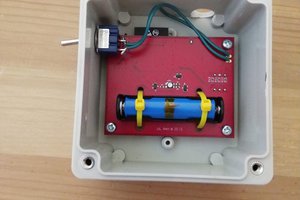
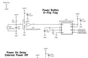
Power for the system is supplied by a pair of AA batteries and a boost converter. The boost converter is the TPS613221A. There is a Schottky diode and snubber circuit in parallel to the chip that is recommended for high current applications (in this case, the audio amplifier can sometimes draw a few hundred mA briefly). The system has soft power control, which starts with a P MOSFET between the battery and the boost converter. The MOSFET gate has two mechanisms to pull it down. First, one output of the controller is an output pin that holds the power on until the software decides to power down. Because the controller has protection diodes to Vcc on its I/O pins, we must isolate them from the !PWR line (which has a pull-up powered from the batteries, and so would potentially be a leakage path). To serve that purpose, there's an N MOSFET that will pull !PWR down when the software outputs a high level on the control pin. But since the MOSFET gate is isolated, there's no chance of power leaking through it. As a bootstrap, any of the game buttons being pushed momentarily draws the pin low, where it will then quickly be held low by the controller (since the boost converter has a bunch of output capacitance we don't have to be too fussy about debouncing the buttons. The caps should be able to easily power the controller long enough for it to pull the !PWR pin on). There are two requirements for this to work. One is that in normal operation, the buttons must be separate to the controller, but any of them should be able to power the system on. Secondly, again because of the controller protection diodes, we must insure that there's no potential leakage path from the P MOSFET gate line. To do this, each button has a common cathode diode array. One anode of each goes to the !PWR line, the other to its I/O pin of the controller. The diodes in front of the controller pins block any potential leakage, and the other diodes isolate each switch from each other despite the common ability to pull down on !PWR when pushed. In order for this system to be reliable, the brown-out detector of the controller needs to be set up. Otherwise, as the power dies it can cause spurious RESETs, and the first thing the firmware does is turn the power on. With a proper brown-out detector, as the voltage falls, the controller is held in RESET with hysteresis to prevent that from happening. The BOD threshold is 2.8 volts because the safe area for the XMega32E5 at 32 MHz bottoms out at 2.7v.
The DAC output is fed into an LM4871 push-pull audio amplifier. It's more or less straight from the datasheet. There is an extra cap in parallel with the feedback resistor to give a little...
Read more » Nick Sayer


 Chris Miller

Insanely awesome idea!!