Close
0%
0%

ESP32-I2S-SLM

Sound Level Meter with Arduino IDE, ESP32 and I2S MEMS microphone

Public Chat
Similar projects worth following
The project aim is to design and build simple but relatively accurate 'Sound Level Meter' with Arduino IDE, ESP32, and commonly available I2S digital microphones.

The basic idea

Sample the sound via microphone, do some filtering and weighting, calculate noise level in real-time on ESP32 and display the result on small screen.

Should be quite simple, however, as usual, the devil is in the details.

Sampling sound with I2S digital microphone

The good thing about digital microphones is that you don't need to worry about the analog part like pre-amplification, linearity and speed of MCU ADC, etc... And the digital values you receive should be already referenced to sound pressure levels (SPL). Datasheet needs to list the amplitude value for certain SPL, for 1KHz pure sine wave tone (i.e. -26dBFS @ 94dB SPL). This is usually expressed as dBFS  (decibel relative to full-scale), so for i.e. -26dBFS you can convert this to absolute amplitude value based on the maximum value mic can send, and in case of 24bit data, this should be (2^23 − 1) * 10^(−26/20) ~= 420426. This is the amplitude you should expect to receive if you i.e. put the microphone inside 'Sound level calibrator'

The microphone of choice for this project is TDK/InvenSense ICS-43434, or more specifically its breakout board available at Tindie. One good thing about this microphone is that its sensitivity is specified as +/-1dB. This means our measurement of 94dB, 1KHz pure sine wave tone, should be -26dBFS, +/-1dB, without any additional calibration. This is pretty good considering I do not have access to any calibration equipment. You can also use the older INMP441 mic, widely available as cheap breakout board on i.e. Aliexpress, but that one has sensitivity specified as +/-3dB.

The hardware

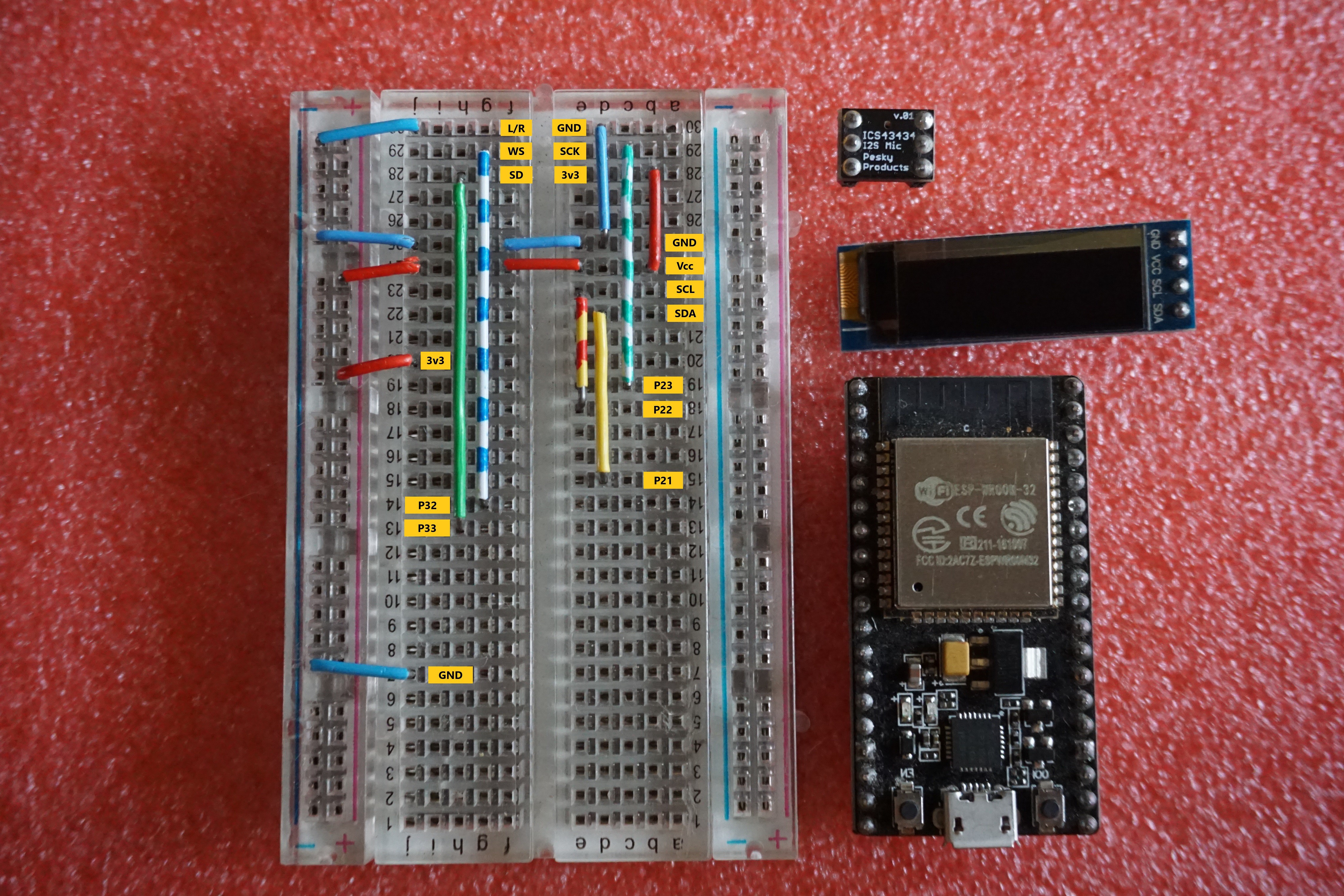
Breadboard friendly, see the list of components
Equalization and weighting

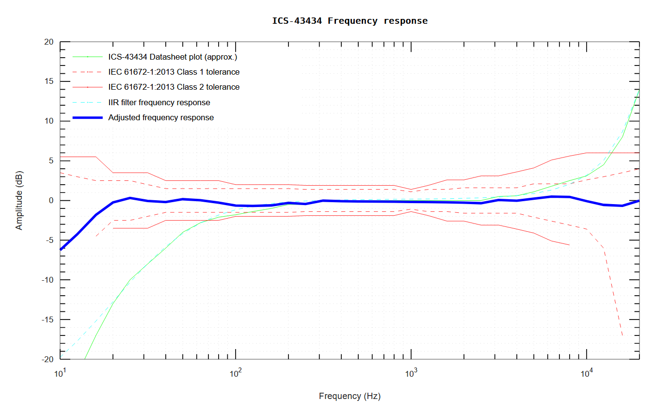
MEMS microphones are usually not ideal and there should be frequency response plot in the datasheet. If this curve deviates outside from acceptable parameters, first we need to equalize (i.e flatten) the microphone native response in the measurement range (20Hz - 20KHz), before we measure the actual SPL levels (i.e. Z-weighted) and apply any weighting filter. We can do this with digital IIR filter designed to (inverse) match the datasheet frequency plot. See the 'ics43434.m' file for my humble attempt at filter design to equalize the ICS-43434. You can copy/paste the math in Octave Online to calculate the coefficients and display the IIR filter frequency response graphs. TLDR, the 'flattened frequency response should look like this (blue line):
Next step is to apply the frequency weighting, in this case the most common (but probably not the most correct) A-weighting, also implemented as IIR filter. The coefficient for this filter were taken from here, for sampling frequency of 48KHz.

Actual implementation of IIR filters is taken (and slightly modified for single-precision and performance) from the nice Arduino digital filter library, and ESP32 with its FPU has the required grunt to do the math continuously while sampling.

The measurement

And from there it is straight forward. I calculate the RMS of the sampled signal, calculate decibels referenced to datasheet value for 94dB and display the value.
Sound level measurements are only meaningful in context of duration of the sampling (see Wikipedia). The Arduino sketch, by default, displays the LAeq(125ms) measurements as horizontal line on top of the screen and LAeq(1sec) measurements as numeric value. It also prints the measured numeric value on the serial monitor and you can graph it with Arduino's 'Serial plotter'

Source code and IIR filter math are available on Github
Confronto_B&K_2250_Vs_MEMS_system.xlsx

sheet - 4.57 MB - 09/08/2019 at 16:12

Download

  • 1 × ESP32 Development board of choice
  • 1 × ICS-43434 breakout Digital I2S MEMS microphone
  • 1 × Small OLED display
  • 1 × Breadboard and jumper wires

  • Back to single-precision with ‘Second-Order Sections’

    Ivan Kostoski11/22/2019 at 16:13 0 comments

    It turns out that if you 'breakup' the higher order IIR filters into series of Second-Order Sections (i.e. biquads), the filtering error does not accumulate as much. With 24-bit data, broken down filters and single-precision, the error induced by the A-weighting filter should be less than 0.5dB in worst case (20Hz). The monolithic 6th order ‘B/A’ transfer function had >7dB error at 20Hz with single-precision. 

    As we are here to hack stuff, It is more likely that parts of this project will be integrated into other more complex projects, with many more sensors and functionality, instead of being used as standalone SLM, so I set my (over)optimization goal to leave as much as possible CPU time for other tasks. And instead of fighting with GCC to produce the code that I know is possible, the end result is going all the way to ESP32/Xtensa assembler...

    Well, now you can lower the frequency of ESP32 down to 80MHz (i.e. for battery operation) and filtering and summation of I2S data will still take less than 15% of single core processing time. At 240MHz, filtering 1/8sec worth of samples with 2 x 6th-order IIR filters takes less than 5ms. The ESP32/GCC assembler implementation is in ‘sos-iir-filter.h’ and in the comments you can find more or less equivalent C code. The sources from esp-dsp were quite helpful. The CPU ISAs these days… let’s just say that my beginnings involved writing 6502 assembler…

    Support for Knowles SPH0645LM4H-B 

    I received a sample of this microphone so I decided to try it out. First, it is not quite compatible with ESP32 I2S peripheral and you need to apply ‘dirty hack’ (directly manipulating ESP32 registers, see the code) to even receive the MSB of I2S data. Additionally, the received values have ‘DC bias’ (or offset) so calculating SPL RMS directly is not possible. If you apply DC-blocker filter (or more specifically, DC-Blocker SOS section), this bias can be filtered out.

    While it finally works, in my humble opinion, this microphone is not very well suited for sound level measurement, mostly due to its limited dynamic range (18 valid bits in I2S data) and the errors that will be added by any IIR filters at lower amplitudes, no matter what kind of arithmetic precision you use.

  • When signle-precision is just not good enough

    Ivan Kostoski09/29/2019 at 07:08 0 comments

    It turns out that doing single-precision (24 bits mantissa) math on IIR filters may not work well for frequencies below 40Hz (sampling rate 48Khz). The A-weighting filter was not attenuating the signal enough (error in range of >10dB),

    Easily fixable by replacing 'float' with 'double'. That however, on ESP32 which only has single-precision hardware FPU, comes with big performance penalty. While using only one 6th order IIR filter was still OK, using 2x 6th order filter needed ~122ms just for filtering 125ms sampled data, i.e. just a bit too slow.

    ESP32 silicon should have the 'double precision FP acceleration pkg' (more info here) and 'XCHAL_HAVE_DFP_ACCEL' macro is defined in esp-idf. That would have taken care of the problem. Sadly, it seems GCC doesn't know how to use these instructions on and there is no public record of the accelerated libraries mentioned in the application note. Due to the extra registers involved, I assume this may also have impact on FreeRTOS context switching...

    Another way around this is to use fixed-point math, with i.e. .32 precision. Again, GCC doesn't have __int128 implementation on 32bit platforms, so that had to be added as well...

    Anyway, I have updated the sources with .32 fixed-point implementation of the IIR filters which is fast enough (2x compared to software emulated double-precision) and good enough so error at low frequencies (down to 10Hz) is <=0.1dB. As we are dealing with 24bit microphone values, there should be low risk of fixed-point overloading. The code is not very well tested, but seems to work for microphone sampled data.

  • Comparative measurements with B&K 2250

    Ivan Kostoski09/08/2019 at 16:26 0 comments

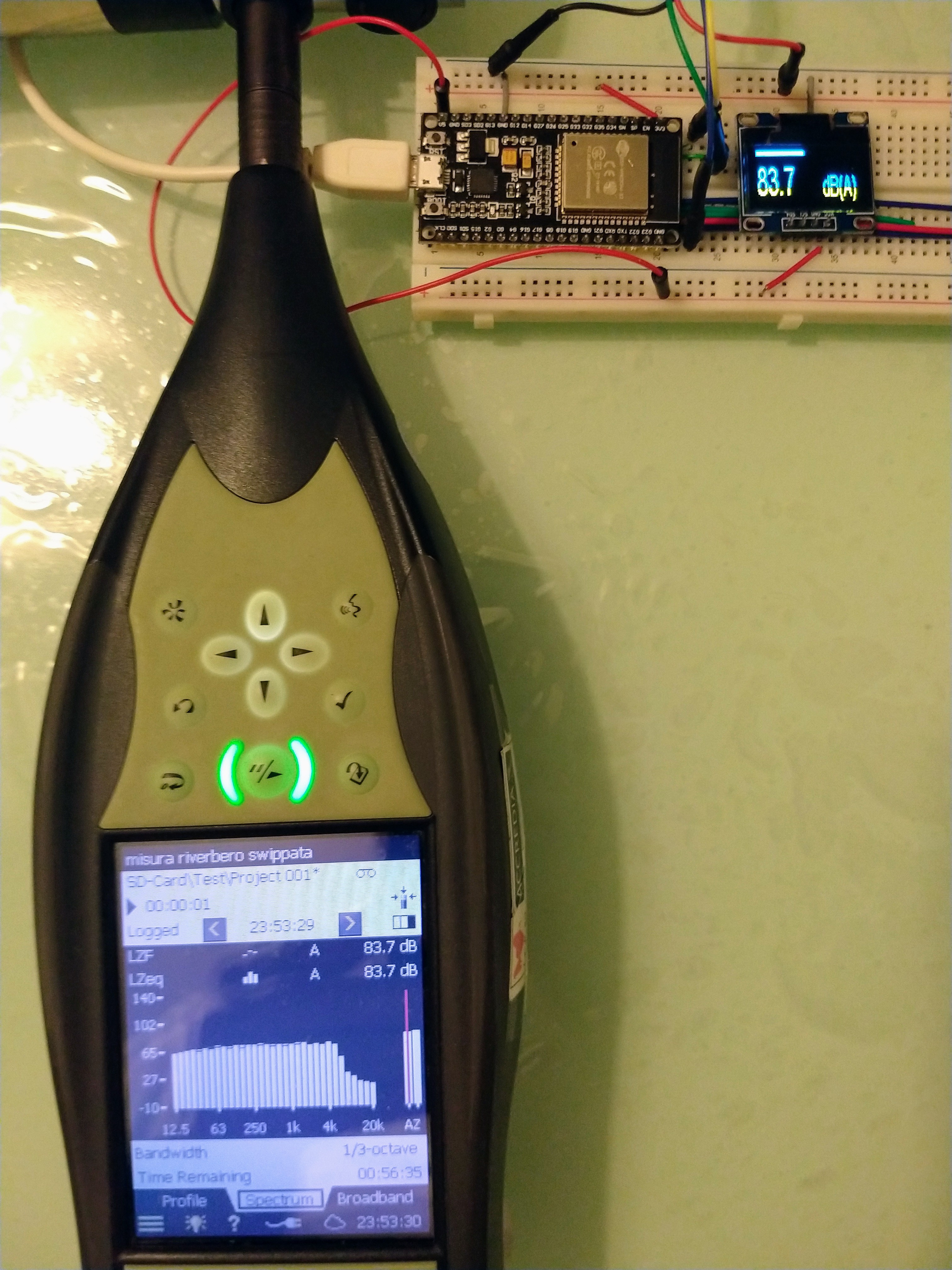
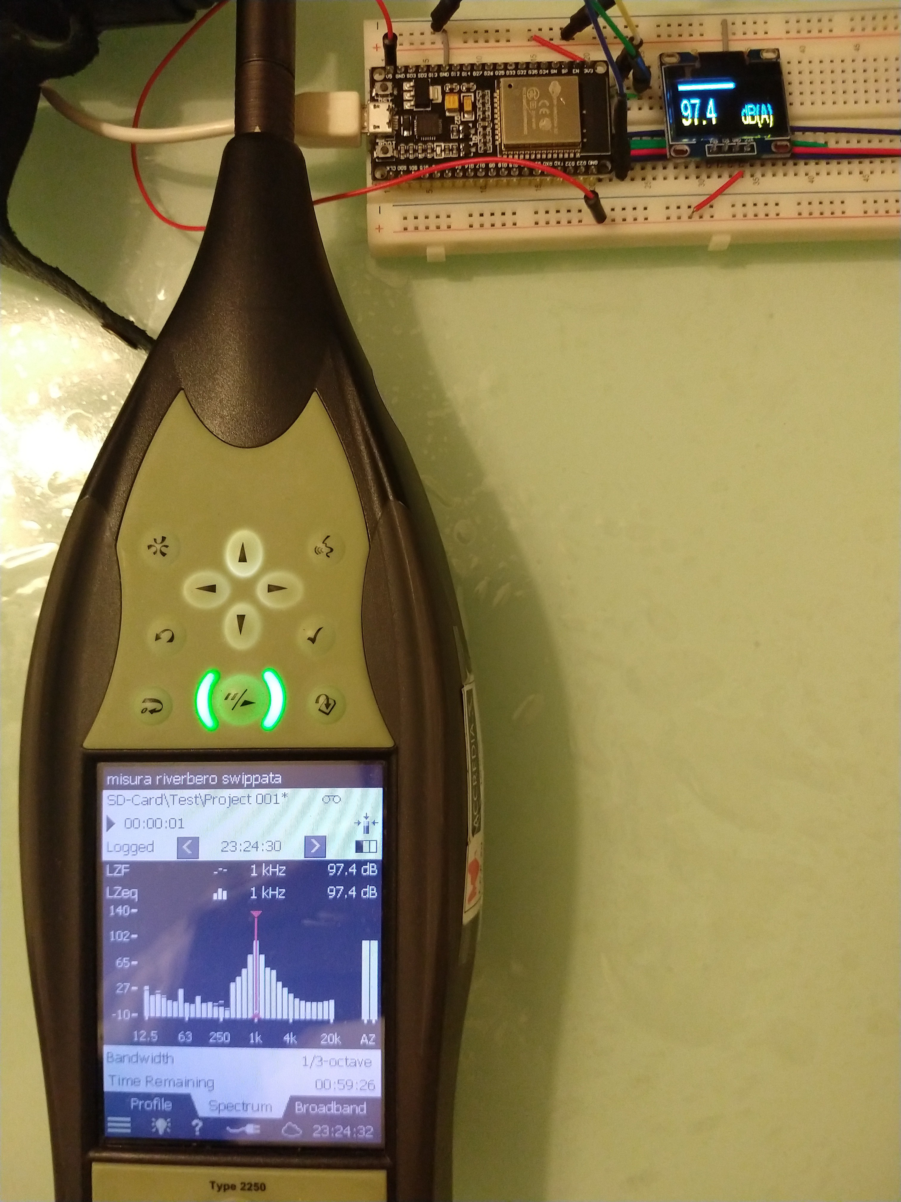
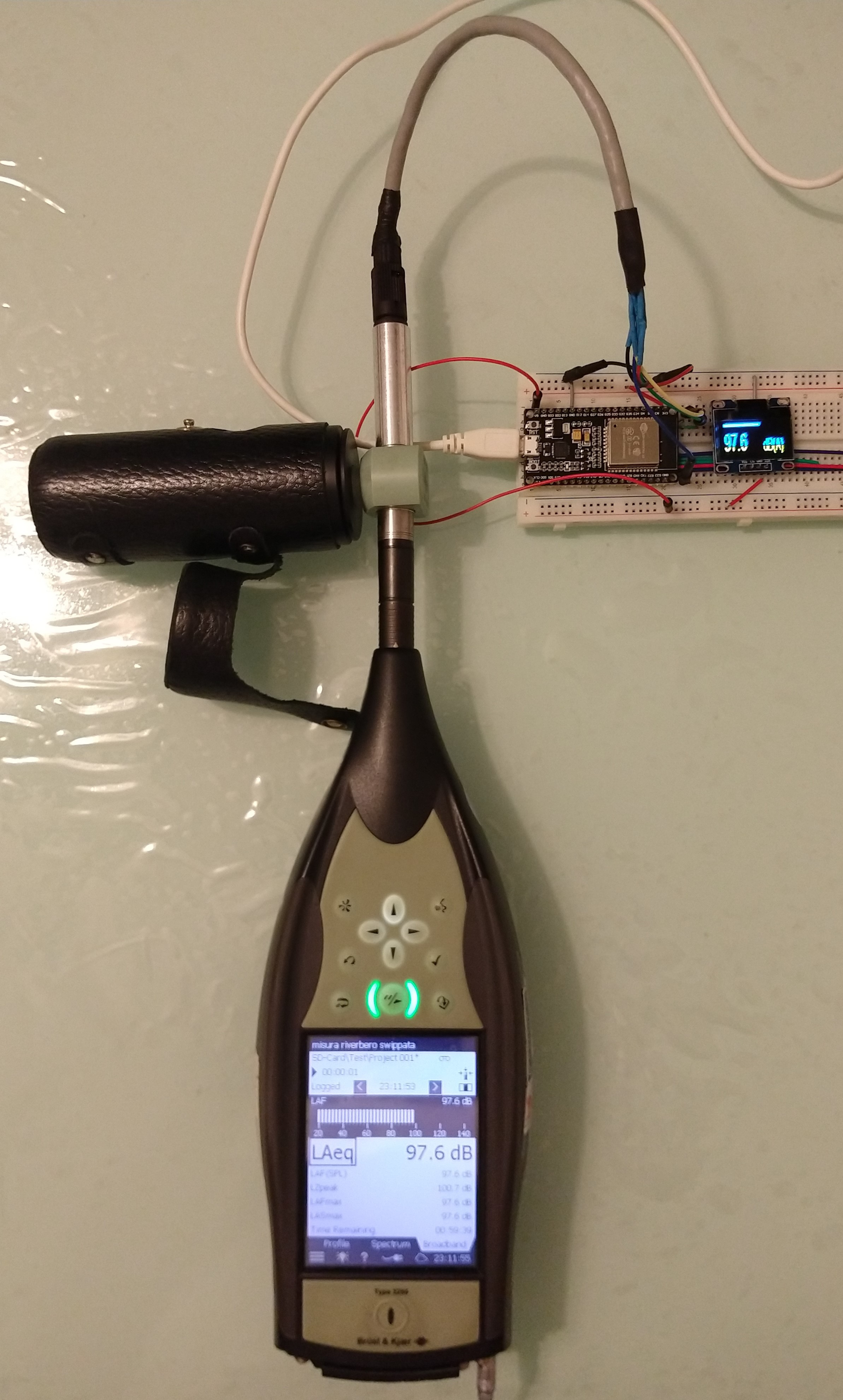
    If you are wondering if the theoretic accuracy of this simple and cheap SLM has any practical meaning, here are some measurements in comparison with IEC-61672-1, class 1, Brüel&Kjær 2250 sound level meter, courtesy of D-r Enrico Armelloni.  

    The MEMS microphone used in the test is ICS-42432 (slightly older, and perhaps more accurate model), in protective shell which also acts as 1.27mm adapter, connected to ESP32 running the GitHub sketch. D-r Armelloni went to great length testing the MEMS+ESP32 setup, including various sound amplitudes, frequencies, pink and white noise, etc...  


    The detailed calibrated results so far are in the excel file in the ‘Files’ section.

    Please have in mind that this is probably the best-case scenario, i.e. it is not expected that every single piece of MEMS microphone will produce such close results. And if you wish to be confident in the measurements, you will need to do similar calibration on your setup. Also note that the range of the used MEMS microphones is about 35dB to 116dB and not suitable for i.e. low noise measurements.

    What test does validate is the principle of how noise is calculated based on sampled sound from I2S microphone. On D-r Armelloni's advice, I also removed all misleading references to 'Fast' and 'Slow' in the project description, as the code never did any time-weighting on the sampled values. It only calculates LAeq values for various periods, which I believe is currently the most useful metric.

View all 3 project logs

Enjoy this project?

Share

Discussions

Digilamer wrote 10/01/2024 at 08:58 point

I have project where I need to measure levels up to 120dB (included) of white noise or a 3KHz tone. The MEMS mics supported by this code have a limit of 116/120dB, so I cannot detect if the sound is higher than 120dB. I made some tests using the MSM261S40030H0 MEMS mic (that supports up to 140dB). I used the SOS_IIR_Filter settings of IM69D130, just for a test. I compared the results with an expensive Svantek SLM for levels between 60 and 120dB of white noise: from 60 to 115dB they are practically identical (great!), over 115dB, the MEMS mic result is lower than the result of the Svantek SLM by around 2dB, though. For all the 3KHz tones between 60 and 120dB the MEMS mic level is always around 1dB less than the Svantek. How can I find the correct settings for this MEMS mic? Is it possible? Thanks in advance for any suggestion. 

  Are you sure? yes | no

DJ wrote 07/01/2024 at 20:20 point

When I try to compile the program in Arduino IDE I get errors - error: designated initializers cannot be used with a non-aggregate type 'SOS_IIR_Filter' - for all the instances where SOS_IIR_Filter is used. Is there a setting I am missing or something else?

  Are you sure? yes | no

Digilamer wrote 10/01/2024 at 08:40 point

I solved this using an older Expressif ESP32 board library (2.0.17 instead of 3.0.5). The error is gone and I can compile and run with no issues.

  Are you sure? yes | no

mitzu_stefan wrote 10/13/2023 at 11:14 point

Hello can someone help me with the source code? i just made the circuit, but i dont have an lcd display right now, and i want to read the data by serial monitor, 

Serial.printf("%.1f\n", Leq_dB); this part of the code only give me on serial monitor -nan

  Are you sure? yes | no

Tim wrote 03/16/2023 at 16:47 point

Hello Ivan.  Firstly love this project and I've learnt masses already.  Struggling to get my head around some of the code but heck, learning hurts (well, me anyway)! 
I'm trying to modify to have two microphones, each producing a weighted Leq_RMS using I2S synchronised L/R channels.  i.e. tie the ICS43434 SD and BCLK lines and set the I2S channel_format: I2S_CHANNEL_FMT_RIGHT_LEFT.  2 channels means twice the samples, but they come in alternately depending according to the WS state, if I read the datasheet correctly.
I'm guessing the Weighting + SumSquares filters are going to need adapting to pick out the L or R sample data and deal with them separately.   Any suggestions on this approach?, or have you attempted this yourself already?
Reason I want to do this is to detect 2D direction of a moving noise, as well as its SPL.

  Are you sure? yes | no

Eduardo Martinez wrote 02/20/2023 at 12:11 point

Hi Ivan; excellent project, thanks !!! I had a problem: Using VSCcode with PlatformIO and using Espressif32 version 3.3.2, your project run flawlessly using your software as is.... Regrettably, I've changed computer and now, with the new installation of PlatformIO, espressif32 version changed to  6.0.1 and now, printing the sound levels in monitor, all values are "nan"..... May be you can point which is the problem.... also, I tested using last version of Arduino IDE and the result is the same, all "nan" values

  Are you sure? yes | no

Dharmik Patel wrote 11/09/2021 at 10:38 point

Great project,
Got to know a lot more stuff that I never know before. And want to do something similar but just need noise values in dbA. Have tried configuring the project code given in GitHub as per my mic datasheet. But I think I have messed few things or left some configurations due to that I am not getting proper dbA values. Have created a git issue here 
https://github.com/ikostoski/esp32-i2s-slm/issues/12

It will be a great help if someone can point out what I am missing out.

Thank you,
Dharmik Patel

  Are you sure? yes | no

David Grant wrote 05/21/2021 at 13:05 point

Great project! Did you ever quantify the polar response of this mic, with and without the 1/2" chassis you manufactured? Any idea how the polar performance is compared to IEC 61672?

Any further plans for this project? Anything new on the scene in terms of MEMS mics suitable for SLM applications?

  Are you sure? yes | no

Roland wrote 12/16/2020 at 09:05 point

Dear Timm,

thanks for pointing out the LEQ_PERIOD integration time. I totally overlooked this (must have had a weak moment..).
Changing this define to 125 ms made a lot of difference. The noise burst measurements even went better than on the Class 1 RION NA28.
The response of the SLM was faster. Mind you, the measurements are done on my desk having the RION and SLM in the same plane facing a loudspeaker and are highly indicative. However it gives some direction.

BTW I'm interested in a LAFmax value.
But one thing remains, how exactly is LAFmax defined? I can find definitions like the highest level within the 125 ms. But in your B&K document on page 8 there's a mention about a duration longer than 70 ms.
Having a old fashioned SLM with analog filters I can imagine response can happen within the 125 ms. Using IIR filters I'm not so sure.
But this is becoming highly detailed and perhaps of topic for the ESP32 SLM. Could we perhaps discuss this via a PM?

  Are you sure? yes | no

Timm Carson wrote 08/28/2022 at 02:40 point

Sorry I am 2 years late....  not sure how I missed it.  you are correct, taking the highest value within your integration time would be the Lmax.  page 8 deals with how humans perceive loudness and is not relevant to any calcs you are doing.  "loudness" falls under psychoacoustics and is a different thing. 

  Are you sure? yes | no

Roland wrote 12/09/2020 at 14:56 point

Hi Ivan,

kudo's for this project! I've been playing around with your code and it works like a charm! I do have one question. I would like to be able to measure Lmax values. I've extended the code such that it saves max.values for a brief period and present the Lmax next to the Leq value on the display. Seem to work however.. if I measure short noise bursts and compare the Lmax values with a Class 1 Rion NA-28 I see that noise bursts  >0.3 s  give realible values on the Rion NA-28. Your SLM needs >0.7 s. Any idea why your SLM needs a longer time?

  Are you sure? yes | no

Timm Carson wrote 12/09/2020 at 16:12 point

Hi Roland,

Ivan can correct me if needed but, The code as supplied by Ivan uses a 1sec integration time this is equivalent to "Slow" setting on a SLM.  Setting a SLM to "Impulse" changes the integration time to ~35ms.  

The SAMPLES_SHORT block is 125ms long.  to get ~35ms, you will need to do your calculations on 1/4 blocks of SAMPLE_SHORT at a time.

  Are you sure? yes | no

Roland wrote 12/10/2020 at 13:30 point

Hi Timm,

thanks for your answer. It does feel like a 1 s integration time. First I thought it was the DC_BLOCKER DC component remover but that's not used in the code. Looking at the comment in the code the SLM measures in 125 ms (fast) blocks. Applying a noise step (back ground approx. 40dBA to 70 dBA noise level) via a speaker it looks like the SLM needs some time to reach the 70 dBA. It's subtle but it could well be the 1 s integration time. So where is the 1 s integration coming from? 

PS, according to Dutch regulation the Lmax is defined in fast, 125 ms, mode. Not in impulse, 35 ms, mode.

  Are you sure? yes | no

Timm Carson wrote 12/11/2020 at 15:00 point

Roland,

technically you can have LAFmax, LASmax,  LZFmax, LZSmax, or others. it depends on the standard you are using.  a good reference on sound measurements with meters can be found  at the following site:   https://www.bksv.com/media/doc/br0047.pdf

In Ivan's code, you can change the integration time by changing the define

#define LEQ_PERIOD     1     // second(s) 

change from 1 to .125 for a "fast" time

  Are you sure? yes | no

Denny Beulen wrote 11/18/2020 at 20:42 point

Hy Ivan,

I am currently also developing a SPL meter, your project has helped me very much! However, currently I have some problems when there is only environmental sounds. I have a dB meter, (not a very expensive one, around 100 euros) which shows around 34dB in a quiet living room, however the esp does display a SPL of around 50dB.

When i provide both meters with a white noise or any frequency they do show equal measurements.


How is your meter working in a quiet environment? Any Idea's about why this difference is this big?

  Are you sure? yes | no

RSTjordan wrote 07/03/2020 at 09:39 point

Hello Ivan,

Why are you shifting the sampels 8 bit right? is it for converting the 32 bit to 24? but how is this how you do it? it doesnt lead to data loss?

thank you very much!

  Are you sure? yes | no

Ivan Kostoski wrote 07/07/2020 at 19:14 point

Hi Jordan, the microphone datasheet specifies the number of valid bits (i.e. 24 for ICS-43434) in the I2S data, and rest are zeroes anyway. I am just 'normalizing' the data before  converting to 'float' and filtering...

  Are you sure? yes | no

Victor Belov wrote 05/13/2020 at 14:49 point

Great project first of all! Can you please elaborate on how have you put the MEMS microphone into the shell to fit it into the coupler?

  Are you sure? yes | no

Enrico Armelloni wrote 05/16/2020 at 20:42 point

Hi belovictor,

In order to use the 1/2" microphone calibrator I designed the PCB for the MEMS microphone, so I mounted it in an aluminum case (specially made in the workshop) with the diameter of a 1/2" microphone.
You can see the picture of the case here:

https://forum.pjrc.com/threads/44005-Teensy-3-6-and-MEMS-mic-ICS-43432?highlight=earmello

  Are you sure? yes | no

Timm Carson wrote 12/09/2020 at 16:14 point

Hi Enrico,

Would you be willing to share you PCB design?

  Are you sure? yes | no

Walter wrote 10/09/2019 at 19:30 point

Hi, I have acces to a professional acoustic calibration laboratory and can help you further. I am using a MEMS microphone from Infineon. Also have some other ideas which I already implemented and tested using my own code, like a second channel and a DAC output. Let me know if you want to work together and can let me join the project.

  Are you sure? yes | no

Elliot Williams wrote 08/27/2019 at 07:44 point

Great idea to find a (cheap) calibrated part and fill out the rest yourself.  Very cool.

  Are you sure? yes | no

Ivan Kostoski wrote 08/27/2019 at 08:58 point

Thanks. I am waiting for some comparison results with 'real' SLM. Initial test with Bruel&Kjaer 2250 look very promising...

  Are you sure? yes | no

Similar Projects

Does this project spark your interest?

Become a member to follow this project and never miss any updates