David M.
-
07/30/19 - Proper ESP32 boot without USB connection
08/01/2019 at 18:26 • 0 commentsA while back I have encountered a problem with my ESP32 programming fixture. It was resetting the ESP32 if powered with a power supply, however it was fine when powered through a USB plug. To this day, I still haven't figured out what the problem is but here are the steps I took to fully fix the problem:
- Make sure the power supply voltage at the 5V pin on the fixture is between 5.10V and 5.15V. Measure the voltage with a voltmeter, but test that the voltmeter is properly functioning first.
- Check the voltage at 3V3 pin is indeed 3.30 volts.
- Tie pin 12 to ground on boot, explanation below.
- Check the continuity of the wires used. Use the shortest wire path possible if it still doesn't work.
I'm not sure why pulling pin 12 low helps, but according to this reference guide, it definitely shouldn't be pulled high on boot:
https://randomnerdtutorials.com/esp32-pinout-reference-gpios/
When I saw that bit of information I decided to try it out. I pulled pin 12 low and it appeared to help.
I checked pin 12 with a logic analyzer but it did not appear that pin 12 was being pulled high on boot by the fixture.
Further testing showed that if the power input wasn't sufficient, then the ESP32 could still be booted if pin 12 is pulled high first, then low, which allows it to function for a few seconds before it starts requiring more power for WiFi transmission.
-
07/29/19 - Ultrasonic Distance Sensor for second data stream
08/01/2019 at 17:23 • 0 commentsI have gotten to the point of needing to expand my mesh network capabilities. My first thought was to at a third mesh node, but I don’t yet have an elegant hardware solution yet. I could solder up some wires to an ESP module and reprogram it every time by reconnecting wires. However, there are other ways I could develop the project while I think of a better solution. I think I will begin working on two way communication first, and maybe even start trying out some ULP core libraries.
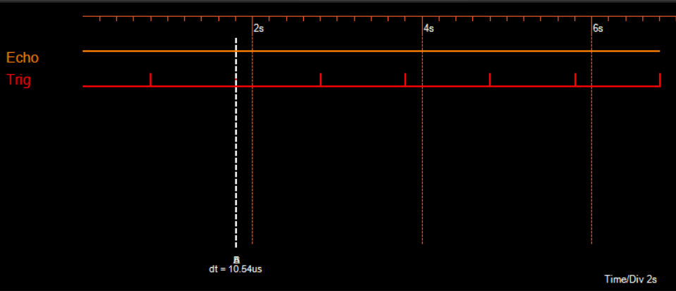
At first, I will connect a second sensor for the second stream of data. I chose the ultrasonic distance sensor, however, while testing it, it appeared to be broken. The echo pin should respond to the 10 microsecond trigger but it stayed high all the time.
Fig. 22 - Five Wire logic capture of the Trig and Echo pins.
-
07/26/19 - Data transmission log on OLED using UCG library
08/01/2019 at 16:51 • 0 commentsMy opinion about the ssd1306 library proved to be true, -- there were better alternatives. I was able to find a better library for the OLED screen with properly formatted functions. This library, called UCG, has the ability to use the ESP32’s hardware SPI to draw on many various screens available on the market, including my SSD1331. I was able to rewrite my previous DHT11 sensor transmission code using the UCG library. The biggest problem I ran into was when the screen was displaying text the moment when the packet captured was writing to the text variable. It didn’t take long to make the screen “crash” after said moment. I fixed it by halting the screen display function while the packet was being captured.
![]()
Fig. 21 - The transmitted DHT11 sensor data is displayed in a log on an OLED screen.
I think my next best step would be to start implementing a third node to start developing the mesh functions. To do this, I would need to combine the slave and master programs into one sketch. To do this properly, I think it would be best to configure my sketch in a way which avoids using a SoftAP to make a connection.
-
07/25/19 - SSD1331 libraries and DHT11 sensor data transmission
08/01/2019 at 16:11 • 0 commentsThe ssd13306 library I’m using for the SSD1331 OLED Screen introduced weird behavior with displaying text on screen. I later found out that the issue was in the inputs to the functions. The function which displays text on the screen asks for a character array, instead of the usual string. Apparently, the function expects the character array to be 1 character longer than the amount of characters needed to write which should contain the null terminator.
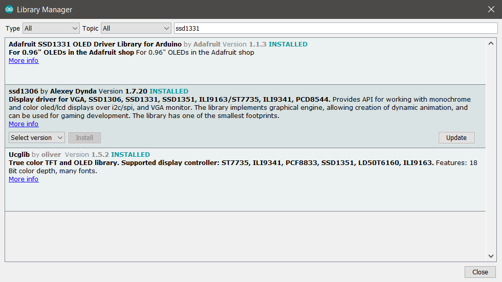
As I dug deeper into this ssd1306 library, I realized just how unfinished and unpolished it is compared to something like from Adafruit. Even though I couldn’t get other more popular libraries to work with ESP’s hardware SPI (Like Adafruit SSD1331 library or SSD_13XX library), I’m starting to reconsider and I’m thinking of giving them another chance.
Fig. 19 - The libraries available for the SSD1331 in the Arduino library manager.
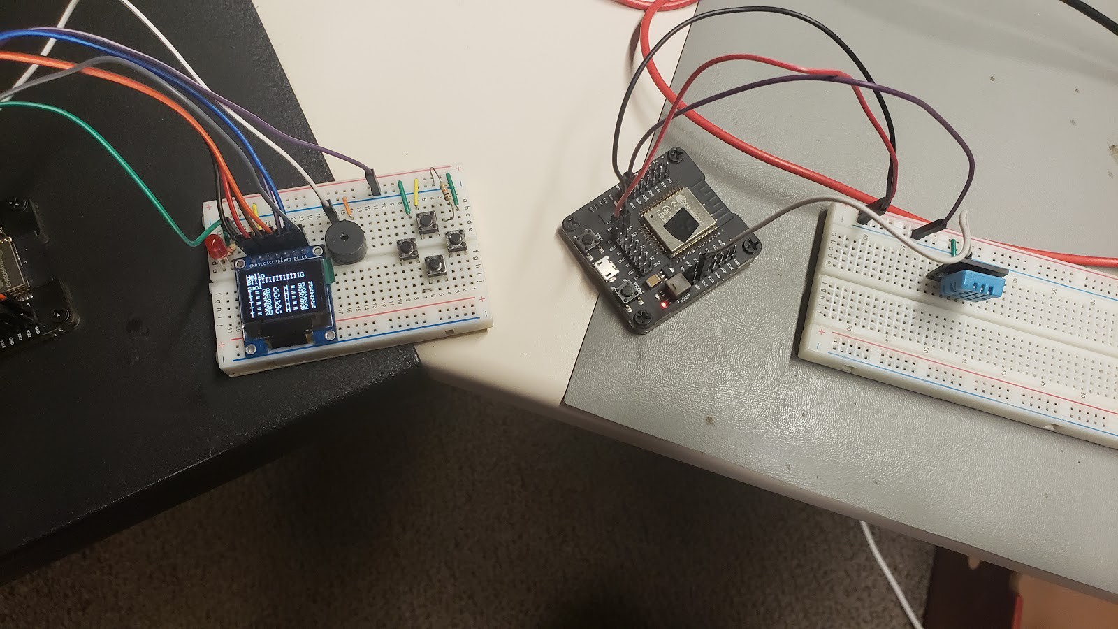
Other than that, I was able to capture temperature and humidity values from a DHT11 sensor, send it from one ESP to another and display it on an OLED:
![]()
Fig. 20 - DHT11 sensor data from one ESP displayed on a screen on another ESP.
-
07/24/19 - Maximum transmission throughput of ESP-NOW
07/31/2019 at 21:01 • 0 commentsTo optimize the code, I let the ScanForSlave function run only once because as I discovered earlier, it took up a significant amount of time. Now, the only two functions which up take the rest amount of the time between transmissions is the manageSlave function and the sendData function itself. I decided to see how much time they take, so again, I toggled a pin for each to see how much time each function takes.
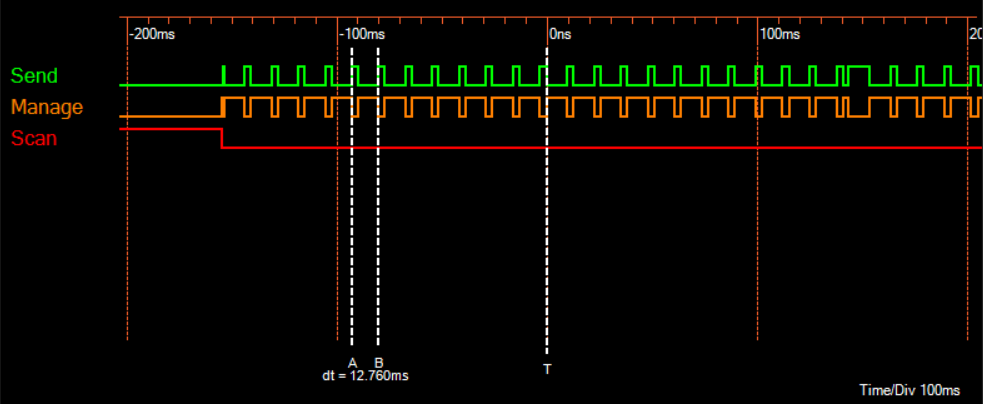
Fig. 11 - The amount of time each function takes and the time between transmissions.
Captured with Five Wire.It appears that the manageSlave function is taking the majority of the time between transmissions. The time between transmissions is about 13 milliseconds on average. I believe it is pretty unnecessary to check if the slave still exists every transmission, so I will make it run only once a second.
void loop() {
  // In the loop we scan for slave
  digitalWrite(4, HIGH);
  ScanForSlave();
  digitalWrite(4, LOW);
  // If Slave is found, it would be populate in `slave` variable
  // We will check if `slave` is defined and then we proceed further
  while (slave.channel == CHANNEL) { // check if slave channel is defined
    // `slave` is defined
    // Add slave as peer if it has not been added already
    digitalWrite(16, HIGH);
    bool isPaired = manageSlave();
    digitalWrite(16, LOW);
    if (isPaired) {
      // pair success or already paired
      // Send data to device
      digitalWrite(19, HIGH);
      sendData();
      digitalWrite(19, LOW);
    } else {
      // slave pair failed
      Serial.println("Slave pair failed!");
    }
  }
}
Fig. 12 - Modified sketch which runs ScanForSlave only once.
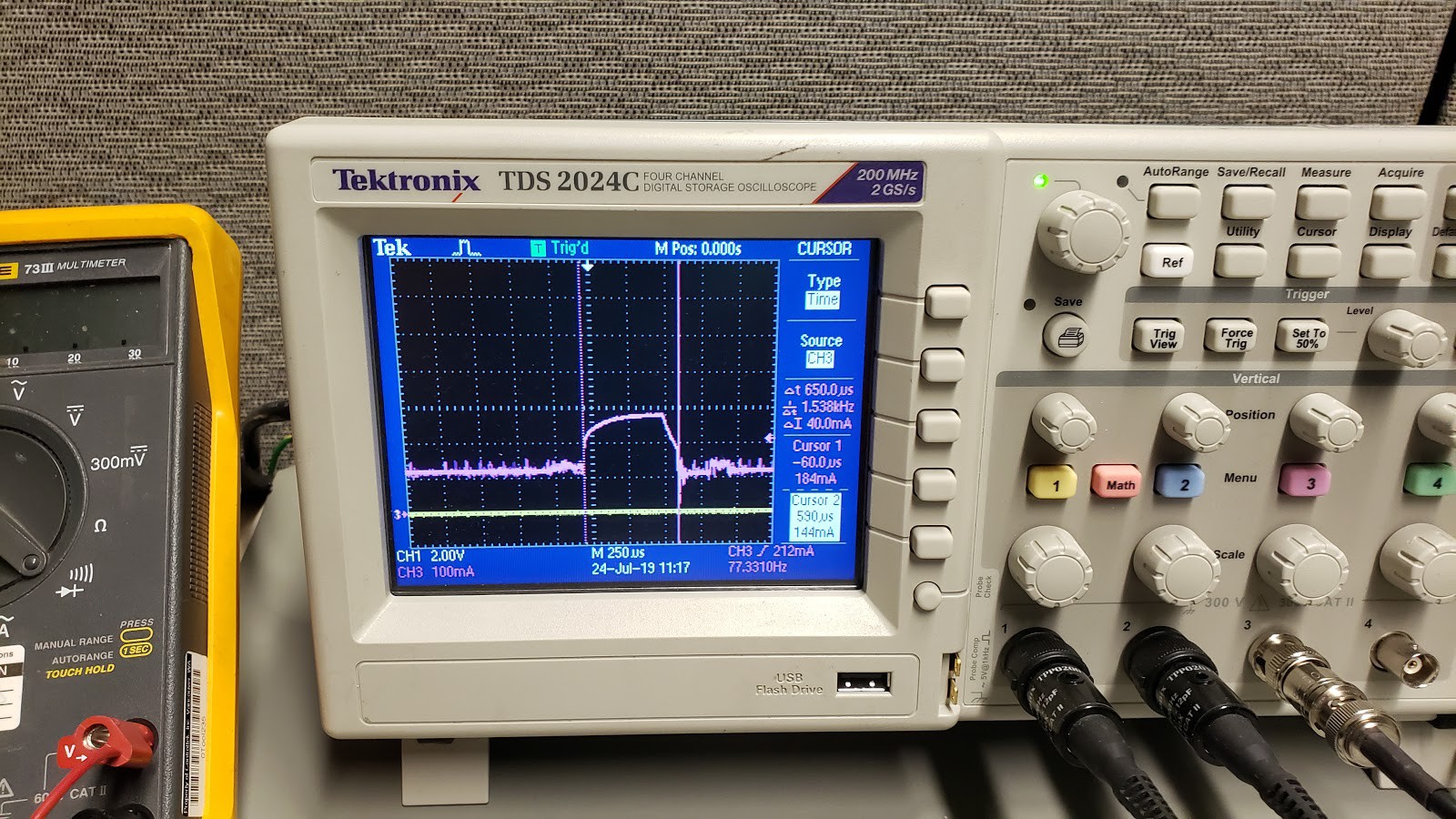
I also wanted to see the current consumption of such a setup, so I hooked up a current meter to an oscilloscope and observed that the transmission took about 650 microseconds.
![]()
Fig. 13 - Tektronix oscilloscope displaying the packet transfer duration and frequency.
It consumed around 120mA during run-time and about 300mA during transmission. This reading, however, included all of the extra peripherals and internal functions, such as LEDs and TTL-to-USB converter. I expect to be able to drop the run-time current down to 80mA. Also, my hope is that I will be able to make use of the ULP core to drop the current consumption down to less than 5mA by the end of the project.
My second step to optimize the code is to make the manageSlave function run only once a second because we don’t really need to know if the receiver is available all the time, just every once in a while.
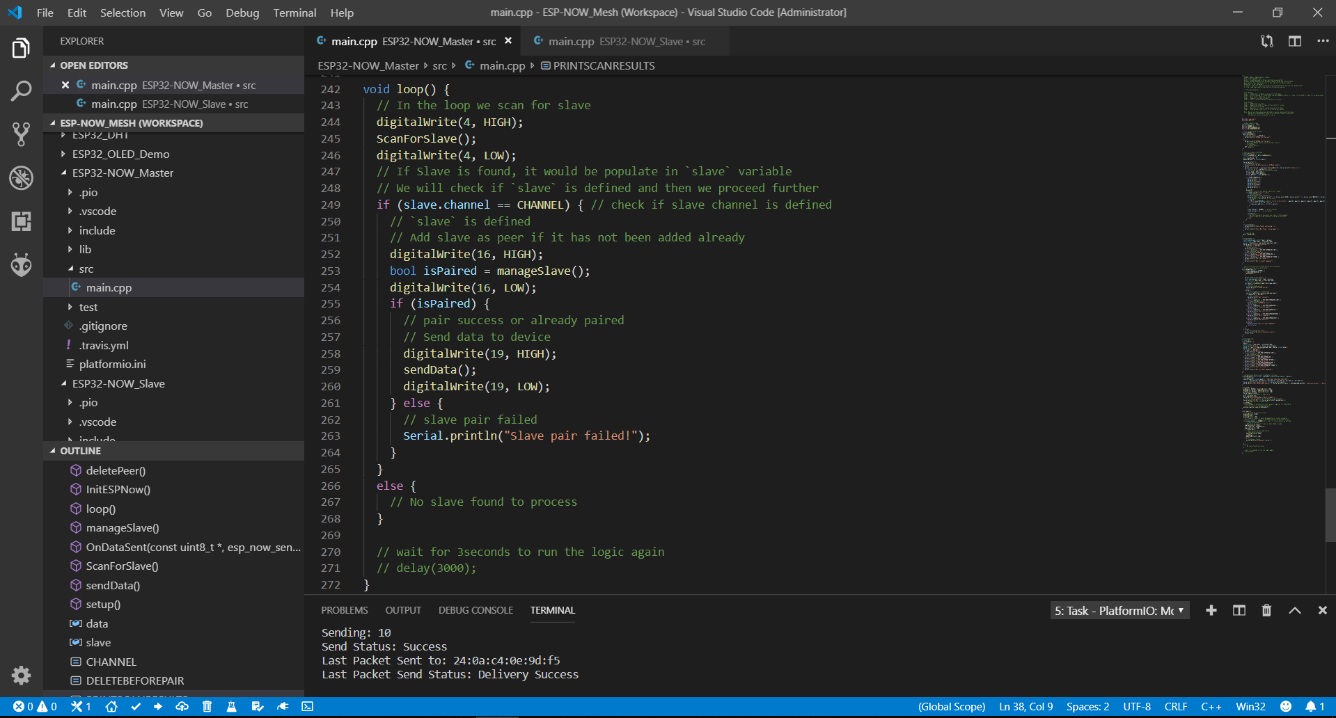
unsigned long nextManage;

void loop() {
  // In the loop we scan for slave
  digitalWrite(4, HIGH);
  ScanForSlave();
  digitalWrite(4, LOW);
  // If Slave is found, it would be populate in `slave` variable
  // We will check if `slave` is defined and then we proceed further
  if (slave.channel == CHANNEL) { // check if slave channel is defined
    // `slave` is defined
    // Add slave as peer if it has not been added already
    digitalWrite(16, HIGH);
    bool isPaired = manageSlave();
    digitalWrite(16, LOW);
    nextManage = millis() + 10000;
    while (isPaired) {
      // pair success or already paired
      // Send data to device
      digitalWrite(19, HIGH);
      sendData();
      digitalWrite(19, LOW);

      unsigned long t = millis();
      if (t > nextManage) {
        nextManage = t + 10000;
        digitalWrite(16, HIGH);
        isPaired = manageSlave();
        digitalWrite(16, LOW);
      }
    }
    Serial.println("Slave pair failed!");
  }
}
Fig. 14 - Modified code which runs manageSlave only once every second.
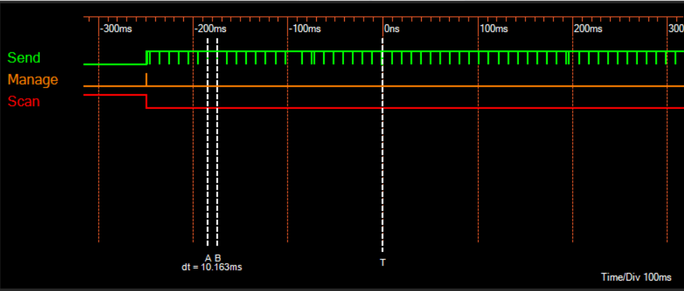
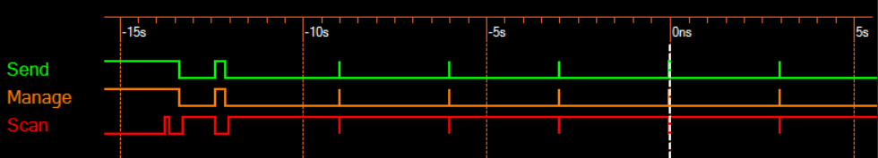
Fig. 15 - The ScanForSlave and manageSlave functions run only once throughout this
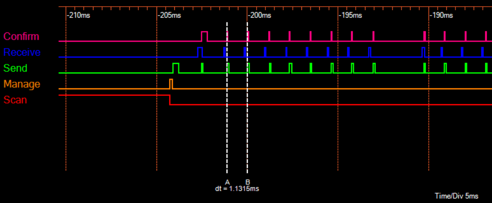
transaction. Captured with Five Wire.This change, however, didn't improve the transmission rate by much, meaning that it could be run multiple times if needed. The time between transmissions is about 10 milliseconds, meaning that the rate is at about 100Hz. This rate, however, includes the serial debugging code on both master and slave ESP's. Let's disable the serial initializer on both, and see what difference it makes. I will connect an additional probe on the receiving ESP and one for the sending ESP which triggers when it confirms the packet has been received.
Fig. 16 - Five Wire logic analyzer displaying transmission behavior where data is sent in chunks.
With serial disabled, the transmission now appears to be sent in chunks. Overall, the transmission rate is much faster, averaging out at 1 millisecond per transmission. The only signal that appears to be consistent is the confirmation of the packet sent. Let's not send another packet until the previous one has been confirmed received.
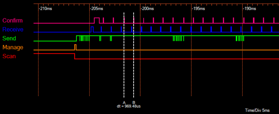
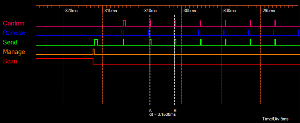
Fig. 17 - Five Wire logic analyzer displaying the new transmission behavior where data is
sent at regular intervals.The time between transmissions is only slightly longer, but with the advantage of being sent at regular intervals. This is all fine and dandy, but what we have tested so far is transmission of packets containing only one byte of data. Let's increase the data up to 250 bytes.
Fig. 18 - The transmission rate has decreased due to a bigger packet size.
Captured with Five Wire.This time, the transmission takes about 3 milliseconds per packet which sets the frequency of transmission at 330Hz at its best. This is, however, without any additional code to even do anything with said data.
What I'm not sure about is whether this ESP-NOW library is using the secondary core in the background during WiFi transmissions in an aim to allow the sketch to run on a separate core. If it is, then this is as far as we can go performance wise. If not, then we can use the secondary core to do the rest of our work while keeping the transmission rate at 330Hz.
-
07/23/19 - Scan for slave only once
07/31/2019 at 20:38 • 0 commentsBeginning with the ESP-NOW example sketches, I became confused as to why the time between transmissions was so large, even if I removed the 3 second delay from the loop of the master sketch. To troubleshoot this problem, I toggled a pin before and after the ScanForSlave, manageSlave and sendData functions and used Five Wire logic analyzer to monitor that pin. The tool made quick work of this debugging process as I was able to see exact timings between operations.
Fig. 8 - The amount of time each function takes. Captured with Five Wire.
The scan for slave pin is high most of the time, meaning that the function is very time consuming. I made ScanForSlave function run only once later on.
Fig. 9 - The example sketch modified to toggle pins 4, 16 and 19 to monitor function timing.
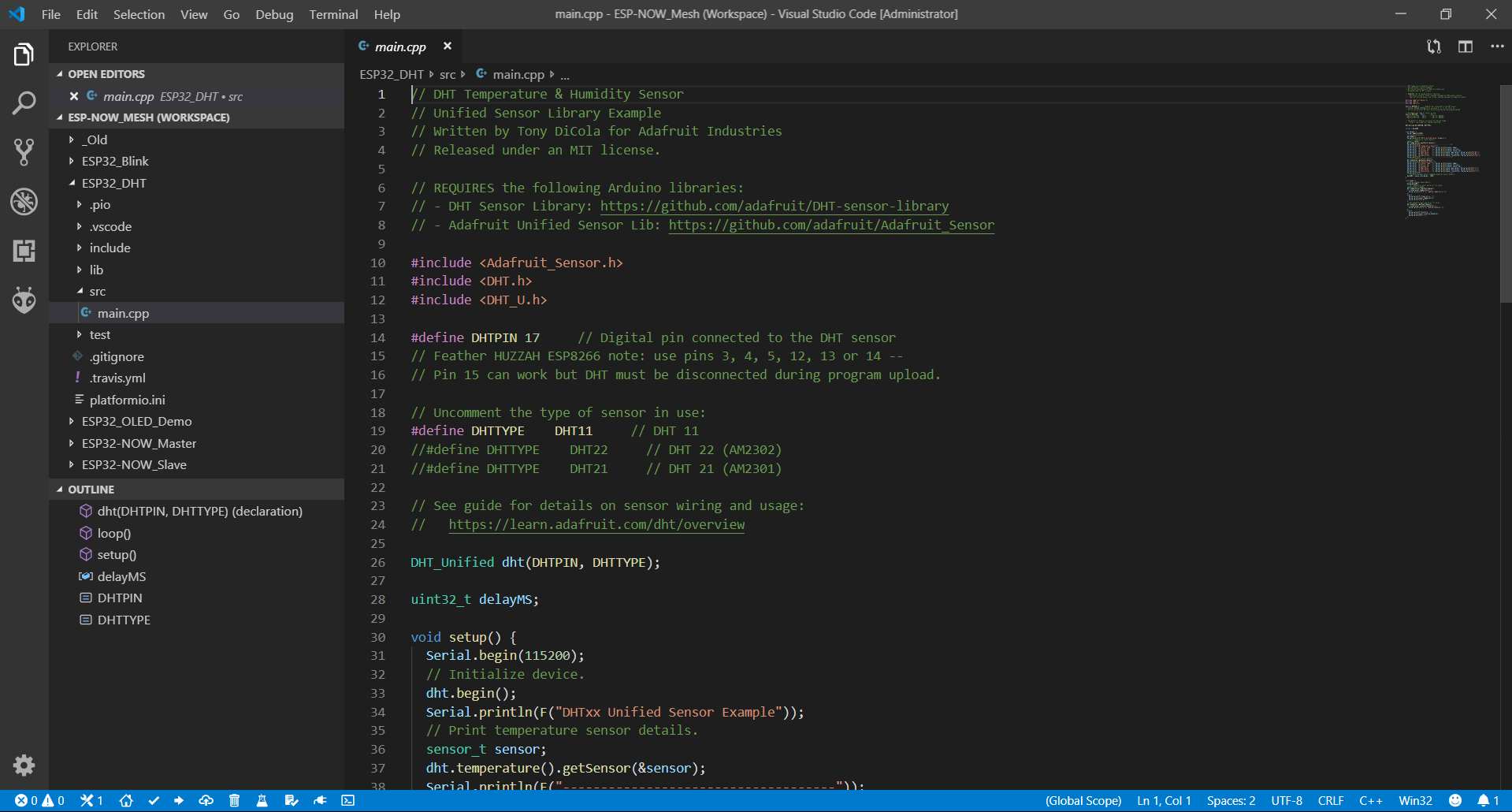
To begin transmitting useful data, I need to choose a sensor for my master node. The first sensor I chose to use is the DHT11 Temperature and Humidity sensor. I was able to make the the Arduino example sketch function and I’m porting it to PlatformIO.
Fig. 10 - Porting DHT11 example sketch to PlatfromIO
-
07/22/19 - Beginning development with ESP-NOW
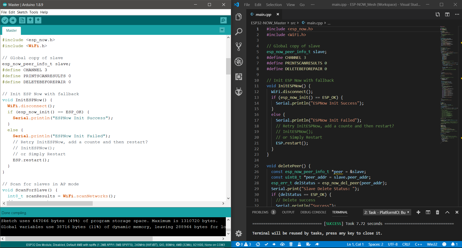
07/31/2019 at 19:23 • 0 commentsI have received my second ESP32 fixture which meant I could begin testing with ESP-NOW. I fired up the example sketches through Arduino, which worked as expected. Then I ported the sketches from Arduino to PlatformIO.
Fig. 7 - Porting ESP-NOW demo from Arduino to PlatfromIO
-
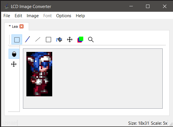
07/19/19 - 16bit images into 8bit array using LCD Image Converter
07/31/2019 at 18:50 • 0 commentsI have figured out how to convert bitmaps into proper 16bit format divided into an 8bit array, and the first sprite test was a success. The sketches were fully ported to PlatformIO.
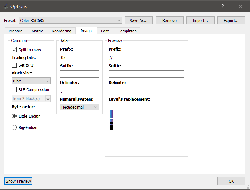
Fig. 5 - The settings I have used in the LCD Image Converter options window
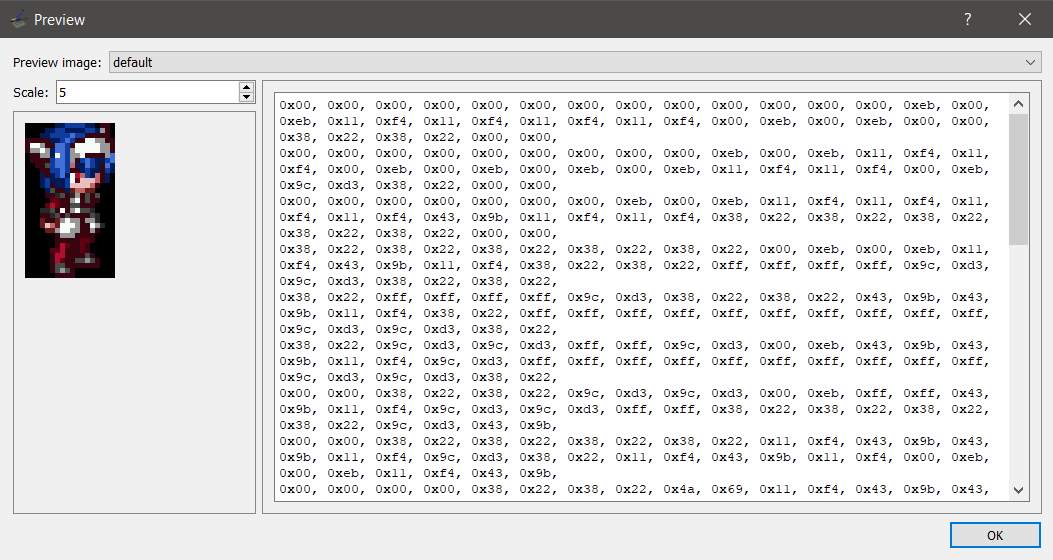
Fig. 6 - The resulting 16bit image in an 8bit array
-
07/18/19 - Converting Bitmap Images into 8bit arrays
07/31/2019 at 18:42 • 0 commentsI found a way to convert bitmap images into an 8bit format, but 16bit images prove to be a challenge. The only way I was able to display a 16bit image so far is by converting one manually.
I found a couple tools to help me convert bitmaps: "lcd-image-converter" and "LCDAssistant". The lcd-image-converter, however, looks to be more capable, so I will try to figure it out.
Fig. 4 - lcd-image-converter main window
-
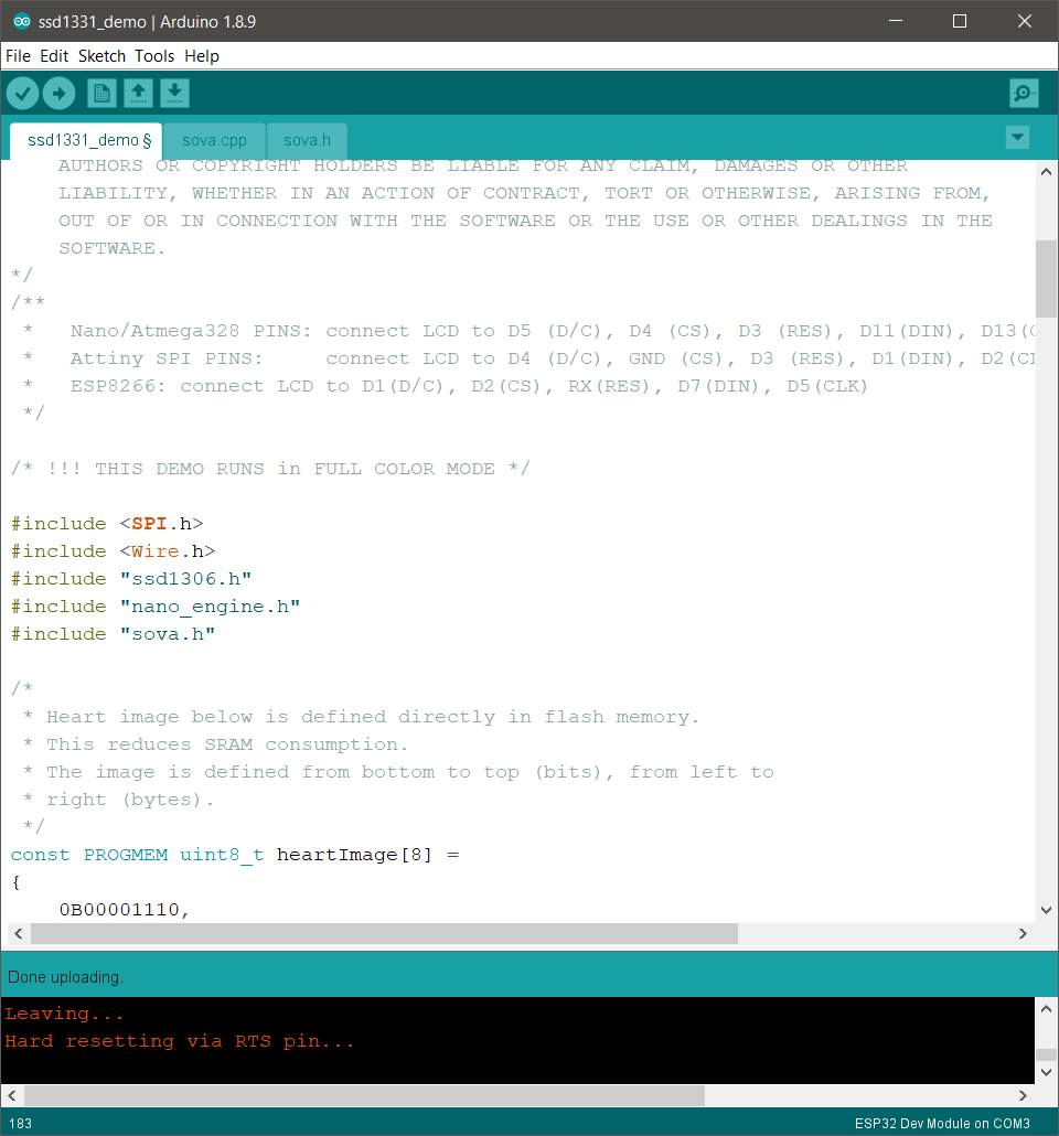
07/17/19 - ESP32 Hardware SPI to SSD1331 OLED with "ssd1306" library
07/31/2019 at 18:34 • 0 commentsIt took some time, but I finally found a library for the SSD1331 OLED which makes use of the hardware SPI called "ssd1306". This library made use of the VSPI, leaving HSPI free for other peripherals if needed. Note for readers: the V in VSPI and H in HSPI doesn't mean Virtual or Hardware, they have no meaning. The display writing rate was significantly faster than software SPI like the one used in SSD13XX library or the Adafruit SSD1331 library (I couldn't get the hardware SPI work with the Adafruit library). The maximum refresh rate for displaying full screen 16bit images was left to be determined.
![]()
Fig. 2 - Arduino sketch window of the "ssd1306" library demo for SSD1331
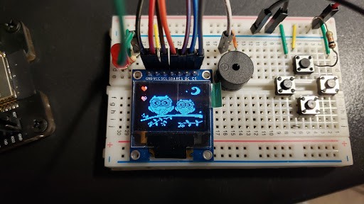
![]()
Fig. 3 - SSD1331 OLED displaying a bitmap through ESP32's hardware SPI
My attempt at an ESP-NOW Mesh
Designing a custom mesh for sensors, home automation and remote controlling using Espressif's ESP-NOW