ziggurat29
-
Persistent Settings
08/11/2019 at 21:12 • 0 commentsSummary
A simple means of persisting settings across boots is realized. A Flash resource crisis has manifested.
Deets
Many projects need to have settings that are persistent across boots. In this case, at a minimum is the setting that contains the operator call sign, since that can't be gleaned from the environment. Practically, several other persistent settings will exist, such as the Transmit Power level, the frequency on which to operate, the bit rate of the GPS serial port, etc.
The STM32F103 processor does not have any EEPROM resources, but this is emulated by using the last flash page as the persistent store. Essentially, the settings are defined in a struct, and this struct is persisted to that flash page. There are some defaults that are defined if the page is found to be empty.
The settings presently defined are:
typedef struct
{
    uint32_t    _version;    //should always be first, should be PERSET_VERSION

    //'dial' frequency for the WSPR channel.  WSPR works in a USB narrow
    //(200 Hz) band within a conventional USB channel.  The center of that
    //200 Hz band is 1.5 KHz above the dial frequency.
    uint32_t    _dialFreqHz;
    //the WSPR signal is extremely narrow-band (6 Hz).  The 200 Hz WSPR band
    //can accommodate 33 1/3 of these 6 Hz sub-bands.  We can be configured to
    //use a specific one, or a negative number means randomly pick one at
    //transmit time (the usual case).
    int32_t     _nSubBand;        //0-32; or < 0 to randomize
    //duty cycle (i.e. how often to try to transmit, randomized)
    uint32_t    _nDutyPtc;        //percent

    //call sign
    char        _achCallSign[8];  //6 chars max
    //explicit grid locator
    char        _achMaidenhead[4];    //4 chars always
    //transmit power level
    int32_t     _nTxPowerDbm;    //0-60, though only 0, 1, 3, 7 endings

    //use GPS (i.e. auto time sync auto grid locator, and wait-for-lock)
    uint32_t    _bUseGPS;        //boolean
    //GPS bit rate
    int32_t     _nGPSbitRate;    //9600 default, but can be other

} PersistentSettings;
The defaults are:
const PersistentSettings g_defaultSettings =
{
    ._version = PERSET_VERSION,    //must be this
    ._dialFreqHz = 14095600,       //the 20-meter conventional WSPR channel
    ._nSubBand = -1,
    ._nDutyPtc = 20,
    ._achCallSign = "",            //you must set this
    ._achMaidenhead = "",          //you must set this
    ._nTxPowerDbm = 20,            //100 mW
    ._bUseGPS = 1,
    ._nGPSbitRate = 9600,          //default for the ublox NEO-6M
};
The gist is that there is a RAM copy of the settings that the program operates off of. Early in the execution of the program (in main()), this RAM copy is initialized from the persistent copy. If there is no persistent copy, then it is initialized from the baked-in defaults.
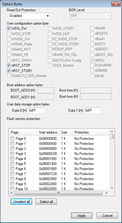
The settings may be persisted by writing the struct to the last page (1 KiB on this device) of flash. An elementary form of wear-leveling is done to reduce the likelihood of wearing out the flash. This works by sequentially writing updates into the flash. Since the erased state of the flash is to cause all values to be 0xff, this is easy to detect. Initial depersistence involves walking through the memory forward to find the /last/ structure that has a valid version number. This is effectively the value of the flash settings. Similarly, persistence means walking through the memory to find the first structure that has the 0xffffffff version number. That will be where the new copy is written. If the page is full when trying to write then it will be erased first. As it stands, this will reduce flash erasures by 25 x. If the structure grows, this will become less effective, but it is also straightforward to add more pages, if needed.
Some test code was put in main.c to repeatedly write structures to verify the functionality. You can use the 'STM32 ST-LINK Utility' to directly view the flash page.
The command processor was updated to include a 'set' command that if used by itself will dump the present settings values, and can be used to alter each of the settings. This only alters the RAM copy of the settings. There is a separate command 'persist' that will write those settings to flash when you get them dialed in the way you want to. Similarly, there is a command 'depersist' to explicitly re-load them from flash. The main() function was altered to do a depersist operation once early during program start up to initialize the RAM copy.
However, now we are in a state of crisis with flash usage. I've been keeping an eye on it for the past few builds, and the 'maidenhead' feature took the flash size to 59188 over previously 57540, for 1648 bytes. This persistent settings feature took the flash size to 63588, for 4400 bytes usage. Now there are 65536 - 63588 = 1948 bytes of flash left, and moreover the persistent settings are on the last 1 KiB page, so really that's just 924 bytes left! And we haven't even begun to support the synthesizer chip, implement the WSPR encoder, or the WSPR task. I don't think all of that will fit in 924 bytes, so I need to address this issue now.
Next
Addressing the flash crisis
-
Maidenhead
08/10/2019 at 16:22 • 0 commentsSummary
A Lat/Lon-to-Maidenhead support routine is produced.
Deets
WSPR (and other amateur (ham) radio things, and even some other folks, too) like to express location in terms of a 'Maidenhead Grid Square Locator'. To wit it's named after Maidenhead, UK. If you were to take the globe and do what is called an 'equirectangular projection':
![]()
source: By Strebe - Own work, CC BY-SA 3.0
wikipedia: Equirectangular Projection
then the maidenhead is simply a scheme for encoding the latitude and longitude into an alternative form. This is useful to hams because it is more compact to transmit than to spell out all the digits of the numeric representation. Also, for many purposes, the extra precision is not needed, so a few characters suffice.
The encoding scheme is straightforward:
- start with lat long and progressively shift out most significant chunks of resolution. The first chunk is special -- the remaining ones are regular and based on 10.
- for each chunk, two symbols will be emitted. The first is for the encoding of the longitude portion, and the second is for the latitude portion. Alternate chunks use a different encoding: alphabetic or numeric. The first chunk uses alphabetic, the second uses numeric, the third uses alphabetic again, and so forth. By convention, the first alphabetic chunk uses uppercase, and the remainder uses lower case, but strictly the system is case-insensitive.
- repeat to any desired resolution.
The reverse decoding is similarly straightforward but I have not implemented that here.
But the Metric
While the US may be the brunt of many jokes about not having adopted to the metric system like the rest of the world, there are aspects of the metric system that veritably no one has adopted. In this case, nearly everyone still does angular measurement in the system Sumerians devised based on 60 https://en.wikipedia.org/wiki/Sexagesimal, rather than the metric system. (To wit, some civil engineering aspects such as surveying do use 'grads' -- the metric equivalent to 'degrees'.) I do find it amusing that we use a system from about 7,000 years ago that was ostensibly created to make things easier on working with your fingers (counting to a high number on one hand) to in the modern technological times still also being used to make things easier on working with your fingers (communicating your location via Morse code). At any rate, this is why the first part of the maidenhead is treated specially. After that it's handled more uniformly.
Code
The first part is to precondition the data. To the longitude is added 180 to make it go from 0 to 360, and similarly to the latitude is added 90 to make it go from 0 to 180. The second part is to then do a 'base-18' encoding of those data by dividing the longitude into 18 zones of 20 degrees, and the latitude into 18 zones of 10 degrees. These are encoded as the symbols 'A' through 'R', upper-case by convention, and are emitted with the longitude first and the lattitude second. This first pair is called a 'fields' and gets of off the sexagesimal. The remaining are encoded more consistently.
The remaining bits of resolution are done in much of the same way, but alternate between using the digits '0' - '9', or the letters 'a' - 'x'. So, when working on a digital portion, the encoding is base-10, and when working on an alphabetic portion the encoding is base-24. By convention, the lower-case letters are used. These are called 'squares' and 'subsquares'. You can repeat this process to arbitrary precision. In this project we only use 4 symbols because that is what the WSPR protocol requires, but the code does not have that limitation. Speaking of code, this is it:
//north latitude is positive, south is negative
//east longitude is positive, west is negative
int toMaidenhead ( float lat, float lon,
        char* achMaidenhead, unsigned int nDesiredLen )
{
    if ( nDesiredLen < 2 || nDesiredLen & 0x01 )    //silly cases
    {
        return 0;
    }
    int maxprec = nDesiredLen / 2;

    //bounds check lon[-180, +180]
    //bounds check lat[-90, +90]
    if (lon < -180.0F || lon > 180.0F)
    {
        return 0;
    }
    if (lat < -90.0F || lat > 90.0F)
    {
        return 0;
    }

    int lonquo, latquo;
    float lonrem, latrem;

    //18 zones of long of 20 deg; 18 zones of lat of 10 deg
    lonquo = (int)((lon + 180.0F)/20.0F);
    lonrem = (float) fmod ( lon + 180.0F, 20.0F );
    latquo = (int)((lat + 90.0F)/10.0F);
    latrem = (float) fmod ( lat + 90.0F, 10.0F );

    char* pchOut = achMaidenhead;

    (*pchOut++) = ('A' + lonquo);
    (*pchOut++) = ('A' + latquo);

    lonrem /= 2.0F;

    int prec = 1;
    while ( prec < maxprec )
    {
        ++prec;
        lonquo = (int)(lonrem/1.0F);
        lonrem = (float) fmod ( lonrem,1.0F );
        latquo = (int)(latrem/1.0F);
        latrem = (float) fmod ( latrem,1.0F );
        if (prec & 0x01)
        {
            (*pchOut++) = ('a' + lonquo);
            (*pchOut++) = ('a' + latquo);
            lonrem *= 10.0F;
            latrem *= 10.0F;
        }
        else
        {
            (*pchOut++) = ('0' + lonquo);
            (*pchOut++) = ('0' + latquo);
            lonrem *= 24.0F;
            latrem *= 24.0F;
        }
    }

    (*pchOut) = '\0';

    return 1;
}
I put in a little temporary test code in main.c to exercise the function completely and it seems to be working as intended. I removed that test code since it was just temporary.
Next
Persistent settings
-
GyPSy
08/09/2019 at 17:52 • 0 commentsSummary
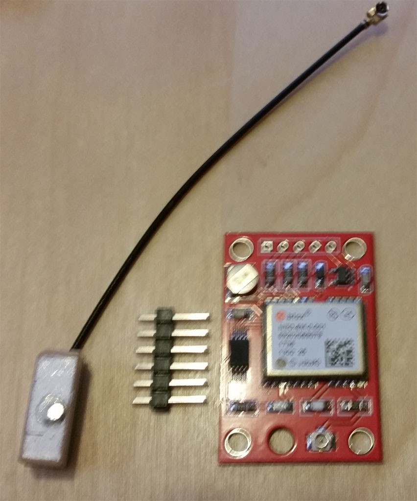
GPS modules have arrived. They're a bit sketchy.
Deets
The Neo-6M modules have arrived. These came with a small bar-shaped patch antenna about 1/3 the size of the square ones I am more accustomed to seeing. I wonder if this will affect sensitivity...
![]()
As a quicky, I connected it via a handy FTDI adapter. This module by default runs at 9600 bps. Data was immediately sent from the module. However, the first lock took about 1/2 hr to be made! However, I am inside, and the limited length of the cables keeps unit close to computer. The tiny antenna possibly does not help, either. I'll order some USB extension cables (which you practically need, anyway, for that ST-Link) and external GPS antenna, though that will take some time for it to arrive. I'm sure it would fare better outside, however that doesn't really work for my development activities.
Receiving Data
This project's needs are very specific, and in fact the only message I need to parse is the standard 'Recommended Minimum C'; e.g.:
$GPRMC,123519,A,4807.038,N,01131.000,E,022.4,084.4,230394,003.1,W*6A
$GPRMC,225446,A,4916.45,N,12311.12,W,000.5,054.7,191194,020.3,E*68
Because of this simplicity I chose not to bother with using an existing library. Instead, I used a simple state machine to capture the text lines, and a trivial parser to tokenize the results on the command and extract the fields. The code is actually a simplified version of what already exists for the command processor, which does a similar thing over the CDC serial port.
//sentence buffer
char g_achNMEA0183Sentence[82];    //abs max len is 82

static char _gpsGetChar ( const IOStreamIF* pio )
{
    char ret;
    pio->_receiveCompletely ( pio, &ret, 1, TO_INFINITY );
    return ret;
}

//this gets characters from the input stream until line termination occurs.
static void _getSentence ( const IOStreamIF* pio )
{
    int nIdxSentence;

    int bCont = 1;

    //pull characters into sentence buffer until full or line terminated
    nIdxSentence = 0;
    while ( bCont && nIdxSentence < COUNTOF(g_achNMEA0183Sentence) )
    {
        char chNow = _gpsGetChar ( pio );
        switch ( chNow )
        {
        case '\r':    //CR is a line terminator
        case '\n':    //LF is a line terminator
            memset ( &g_achNMEA0183Sentence[nIdxSentence], '\0',
                                 COUNTOF(g_achNMEA0183Sentence) -
                                 nIdxSentence );    //clear rest of buffer
            ++nIdxSentence;
            bCont = 0;
        break;

        default:
            //everything else simply accumulates the character
            g_achNMEA0183Sentence[nIdxSentence] = chNow;
            ++nIdxSentence;
        break;
        }
    }
}
so, that fills the statically allocated 'sentence buffer' with incoming characters until either the CR or LF is received, which terminates it.
A new task module was created, 'task_gps.h, .c', and it works much like the one we created for the monitor -- a loop calling the line reception and handling function 'GPS_process()'. Wiring it is was similarly trivial -- just adding yet-another task creation in __startWorkerTasks():
	//kick off the GPS thread, which handles incoming NMEA data
	{
	osThreadStaticDef(taskGPS, thrdfxnGPSTask, osPriorityNormal, 0, COUNTOF(g_tbGPS), g_tbGPS, &g_tcbGPS);
	g_thGPS = osThreadCreate(osThread(taskGPS), NULL);
	}
For the moment I will just be setting some global variables that can be inspected, but later I will add functionality to set the RTC clock to the satellite time, and to update the maidenhead to the current location.
Parsing
The trivial parser then tokenizes the incoming data by converting the comma to a nul. This effectively makes the sentences into a sequence of nul-terminated strings, themselves terminated by an empty string.
Most of the fields are straightforward, but the latitude and longitude are oddballs in that they are degrees and minutes, with the two numbers mooshed together. So we need to separate the numbers and then convert the minutes into decimal degrees. (We want decimal degrees for the forthcoming maidenhead conversion code). I cheated on this and used sscanf() to make the parsing easy.
//the lat/lon is 2 or 3 char degrees, and float minutes
int deg;
float fmin;
sscanf ( pszLat, "%2u%f", °, &fmin );
g_fLat = deg + fmin / 60;    //convert to decimal degrees
if ( 'S' == *pszLatHemi )    //+ is N, - is S
{
    g_fLat *= -1;
}

sscanf ( pszLon, "%3u%f", °, &fmin );
g_fLon = deg + fmin / 60;    //convert to decimal degrees
if ( 'W' == *pszLonHemi )    //+ is E, - is W
{
    g_fLon *= -1;
}
I say 'cheat' because scanf and printf are heavyweight functions. In fact, because we're using the '%f' feature, we have to add some more linker flags or they won't even work as desired
-u _printf_float -u _scanf_float
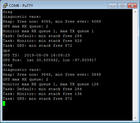
The initial cut of code resulted in a quick trip to the Hard Fault vector. Stepping through the code I could see that the first sscanf did return, but the next line of code crashed. One's first intuition in those sorts of cases is 'stack overflow'. I had given the GPS task 1K of stack (which is twice as much as I normally like), but I guess it's not enough? Doubling it to 2K resolved the crash. I did some inspection via the Monitor:
![]()
So, the GPS task is taking 2048 - 872 = 1175 bytes. This is kind of a lot. It's also interesting to see that in the Monitor task, before issuing the 'gps' command the minimum free is 828 (out of 1K), but after issuing 'gps' it is 136. That is because of the printf ( "%f" ... ) that is performed in the 'gps' command. So that printf is approximately incurring 828 - 136 = 692 bytes of stack usage! (Not all of that is the printf -- some is probably in the command handler, but most is from the printf.)
The build is now 57540 bytes, which is getting very close to the 64 KiB limit of the flash. I'll probably have to revisit this, but we'll see what we can further fit into the 7996 bytes remaining...
Locking
One thing that vexes me and confounds the development is the propensity of this device to take a long time to lock. I can't really debug the code that operates under GPS control effectively if I can't get a lock to stimulate those code paths. I have an antenna on the way which hopefully will help with that, but I did notice a curious part on the board. In the picture of the board above it is in the upper left. It looks a bit like a very tiny battery. It is supposed to hold some parameters in RAM on the chip which help achieve locks more quickly. It's not a critical component, but it helps.
Doing some research on the web, it does seem that some folks have a battery on their NEO-6M boards. It seems likely that the batter is a MS621FE part:
https://www.sii.co.jp/en/me/battery/support/charging-circuit1/
http://www.sih.com.hk/sih_eng/products/bat_02_manganese.htmlThis is a rechargeable Lithium cell. It states that from a deep discharge state that the part support 200 cycles. Egads, 200?! Better not let it ever get discharged.
However, upon further study of the pieces of part number visible (most is hidden by the solder terminal), I am now convinced that my board does not have this part, but instead has a super-capacitor 'XH414H'. This is a 70 milli-Farad cap. Well, at least that has indefinite charge cycles. I have no idea how long the supercap will support the memory, though, so it might not help much in the practical world.
Next
Translation of lat/lon to maidenhead grid locator
-
The Monitor Task and the Command Processor
08/08/2019 at 19:20 • 0 commentsSummary
The skeletal implementation of the Monitor task is implemented.
Deets
The Monitor task is a simple command line interface over a stream interface. In this project, that stream will the the USB CDC interface.
The design is fairly simple: incoming data is built into a fixed-size command line buffer, and when a CR or LF is received, that is interpreted as the end of line, and it is subsequently parsed and processed accordingly. The command line buffer is simply a statically allocated character array of 128 chars. This is expected to be plenty (maybe even too much, but we'll see what evolves).
The FreeRTOS task is straightforward:
- define the FreeRTOS structures needed (the thread handle, the stack, the task control block, and the thread function)
- the task exposes a pointer to a stream interface. This allows binding of the command process to an arbitrary stream.
- the thread function a loop invoking the command processor function
The Command Processor
The command processor is realized with a generic component I use in several projects. This generic component defines a structure:
struct CmdProcEntry
{
	const char*	_pszCommand;
	CmdProcRetval (*_pfxnHandler) ( const IOStreamIF* pio,
                const char* pszszTokens );
	const char* _pszHelp;
};
The intention is that your application will define an array of these structures somewhere. The entries in that array consist of:
- the text that is the command
- a function that handles the command along with any additional parameters
- a short text that is used for the 'help' command
There is a function exposed:
CmdProcRetval CMDPROC_process ( const IOStreamIF* pio,
        const CmdProcEntry* acpe, size_t nAcpe );
This takes the stream on which the command processor is operating and the application-specific array of command entries. This function will build the command line buffer and support things like backspace, etc. When an end-of-line character (CR or LF) is encountered, it will parse the first whitespace delimited token and search in the array of command entries for the handler for that command. It will then invoke the handler function. This lets me easily reuse this common capability amongst several projects. The project-specific part is to define the commands you want and to perform some action when they are received.
The most basic command is 'help', which works two ways:
- invoked by itself, it will list all the commands in the repertoire
- invoked with a token, it will search the command list and emit the help text for that specific command
The handler for 'help' is straightforward and shows how such is constructed:
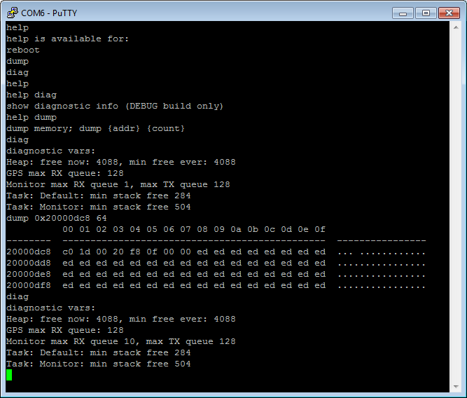
static CmdProcRetval cmdhdlHelp ( const IOStreamIF* pio, const char* pszszTokens )
{
	//get next token; we will get help on that
	int nIdx;
	if ( NULL != pszszTokens && '\0' != *pszszTokens &&
		-1 != ( nIdx = CMDPROC_findProcEntry ( pszszTokens,
                        g_aceCommands, g_nAceCommands ) ) )
	{
		//emit help information for this one command
		_cmdPutString ( pio, g_aceCommands[nIdx]._pszHelp );
		_cmdPutString ( pio, "\r\n" );
	}
	else
	{
		//if unrecognised command
		if ( NULL != pszszTokens && '\0' != *pszszTokens )
		{
			_cmdPutString ( pio, "The command '" );
			_cmdPutString ( pio, pszszTokens );
			_cmdPutString ( pio, "' is not recognized.\r\n" );
		}

		//list what we've got
		_cmdPutString ( pio, "help is available for:\r\n" );
		for ( nIdx = 0; nIdx < g_nAceCommands; ++nIdx )
		{
			_cmdPutString ( pio, g_aceCommands[nIdx]._pszCommand );
			_cmdPutString ( pio, "\r\n" );
		}
	}

	return CMDPROC_SUCCESS;
}
additionally, in debug build, I provide the 'diag' command:
static CmdProcRetval cmdhdlDiag ( const IOStreamIF* pio, const char* pszszTokens )
{
	//list what we've got
	_cmdPutString ( pio, "diagnostic vars:\r\n" );
	char ach[80];
	sprintf ( ach, "Heap: free now: %u, min free ever: %u\r\n",
                g_nHeapFree, g_nMinEverHeapFree );
	_cmdPutString ( pio, ach );

	sprintf ( ach, "GPS max RX queue: %u\r\n", g_nMaxGPSRxQueue );
	_cmdPutString ( pio, ach );

	sprintf ( ach, "Monitor max RX queue %u, max TX queue %u\r\n",
                g_nMaxCDCRxQueue, g_nMaxCDCTxQueue );
	_cmdPutString ( pio, ach );

	sprintf ( ach, "Task: Default: min stack free %u\r\n",
                g_nMinStackFreeDefault*sizeof(uint32_t) );
	_cmdPutString ( pio, ach );

	sprintf ( ach, "Task: Monitor: min stack free %u\r\n",
                g_nMinStackFreeMonitor*sizeof(uint32_t) );
	_cmdPutString ( pio, ach );

	return CMDPROC_SUCCESS;
}
This dumps the memory usage statistics we collected in the Default task.
Another command I usually implement is a 'dump' which simply does a hex dump of an arbitrary memory location. It doesn't really substitute for debugging with the ST-Link, but it is useful in a pinch -- especially when used with the output map file. 'reboot' is also a simple one that is handy at times.
Other commands will be implemented as the project is continued to be fleshed-out.
The Monitor Task
To run the command processor in the project, you just need to do a couple things:
- create the FreeRTOS task that services the processor
- bind the stream interface onto the processor
Since we're going to start creating our own tasks beyond the default one, I create a function:
void __startWorkerTasks ( void )
{
	//kick off the monitor thread, which handles the user interactions
	{
	osThreadStaticDef(taskMonitor, thrdfxnMonitorTask, osPriorityNormal, 0,
                COUNTOF(g_tbMonitor), g_tbMonitor, &g_tcbMonitor);
	g_thMonitor = osThreadCreate(osThread(taskMonitor), NULL);
	}
}
where I kick off the project-specific tasks. You have to define some things:
- a 'task handle' object
- a 'task buffer' (really, this is the task's stack)
- a 'task control block'
- a 'task function'
Since this project's tasks live forever, I define them as static tasks. This simply keeps the allocation of the above mentioned items out of the heap and into globally defined objects. There's not really anything magical to this other than saving a small amount of RAM (otherwise used by arena headers in the heap), and a little more visibility into the memory footprint. (And ostensibly reduced heap fragmentation potential, but that wouldn't be an issue here since they happen to be allocated before anything else and are permanent residents.)
The memory allocations are straightforward and you can use the ones generated for the 'default' task as a pattern. I put those definitions in the task's own source file, though, and define the objects as 'extern' in the header. Then include that header in main.c so they have visibility. The generated code from CubeMX has much more in main.c than I would like for my tastes, but I find it's better to not fight the code generator -- it's just an exercise in frustration.
The 'task_monitor.h' is very simple, exposing just what is required:
#include "cmsis_os.h"
#include "system_interfaces.h"

extern osThreadId g_thMonitor;
extern uint32_t g_tbMonitor[ 256 ];
extern osStaticThreadDef_t g_tcbMonitor;

extern const IOStreamIF* g_pMonitorIOIf;	//the IO device to which the monitor is attached

void thrdfxnMonitorTask ( void const* argument );
The implementation of the task thread function in 'task_monitor.c' is also very simple because I put the machinery of the command processor in the separate implementation described above
#include "task_monitor.h"
#include "task_notification_bits.h"
#include "command_processor.h"
#include "CarelessWSPR_commands.h"

//the task that runs an interactive monitor on the USB data
osThreadId g_thMonitor = NULL;
uint32_t g_tbMonitor[ 256 ];
osStaticThreadDef_t g_tcbMonitor;

const IOStreamIF* g_pMonitorIOIf = NULL;	//the IO device

void thrdfxnMonitorTask ( void const* argument )
{
	for(;;)
	{
		while ( CMDPROC_QUIT != CMDPROC_process ( g_pMonitorIOIf,
                        g_aceCommands, g_nAceCommands ) )
		{
			//(if you wanted to process the return value, but I don't)
		}
		//(we would get here if one of our handlers returned CMDPROC_QUIT,
                //but none of ours do, and even if they did, we do not want this
                //task ever to quit, so we infinite loop in the forever loop, above.)
	}
}
Wiring It In
Once that is done, then you just need to bind the interface to the USB CDC (or you could use UART2 if you wanted) and kick off the task. I do this right after I do the serial init's in the Default task:
	//bind the interfaces to the relevant devices
	g_pMonitorIOIf = &g_pifCDC;		//monitor is on USB CDC
And then before we start the default task's 'forever' loop, we start up the other tasks:
	//start up worker threads
	__startWorkerTasks();
And that is all there is to it! For adding commands, you just define new
handler entries and add them to the list.
Here's an example of a usage session:
![]()
Not especially fancy out-of-box, but all manner of prettification is possible if desired. Shown is dump of the heap on this particular build, the address of ucHeap was found in the output.map file in the 'Debug' directory. You can see the arena header of the first block, and the 'empty data' fill pattern.
Finally, my NEO-6m modules have arrived, so it's probably time to work on the GPS task.
Next
Implementing the GPS task
-
USC CDC Streams and Serial and HAL Fixups, 002
08/07/2019 at 14:25 • 2 commentsSummary
The streamification of serial ports continues with the USB CDC peripheral. This one require more HAL hacking than the UART.
Deets
The Blue Pill has a USB device peripheral that we have just been using for power up to this point, but I do want to make it a serial port that can be used for making settings. As before, I want to abstract that serial port behind the stream interface that was built-up in the prior post.
With the UART, the HAL interface had some awkwardness that was worked around in user code. In this case, though, the USB CDC driver has greater deficiencies, and we have to make modifications in the library code itself. This has consequences: modifications to any code outside of the 'USER CODE BEGIN ...' and USER CODE END ...' will be overwritten each time we re-run CubeMX. The project is already exposed to this with the alternative heap implementation, so I created a batch file that restore these various fixups after running CubeMX.
The major sticking point in this case with the USB is that there is no way of knowing when a transmission has completed. We need that so that we can continue to feed the transmission with data from our circular buffers until completed. We had some callbacks in the case of the UART, but nothing of the sort in the case of USB. So we create some of our own.
The first surgery is to:
Middlewares/ST/STM32_USB_Device_Library/Class/CDC/Inc/usbd_cdc.hIn this case, we add add a new method TxComplete that we will use to receive notification of transmission completed. This addition is put in the structure that is defined around line 100:
typedef struct _USBD_CDC_Itf
{
  int8_t (* Init)(void);
  int8_t (* DeInit)(void);
  int8_t (* Control)(uint8_t cmd, uint8_t *pbuf, uint16_t length);
  int8_t (* Receive)(uint8_t *Buf, uint32_t *Len);
/* USER CODE BEGIN MyCDCExt */
  void (* TxComplete)       (uint8_t *, uint32_t );
/* USER CODE END MyCDCExt */

} USBD_CDC_ItfTypeDef;
Note I made up my own 'USER CODE BEGIN MyCDCExt'. This is purely for my eyeballs, as these are /not/ honored by CubeMX. It seems CubeMX has an internal, hard-coded, set of tags and it disregards all others.
While I was in this code, I also made a non-critical change a few lines down:
typedef struct
{
/* USER CODE BEGIN MyCDCExt */
//hack; this chip is FS only, so why do I want to waste 448 bytes?
//  uint32_t data[CDC_DATA_HS_MAX_PACKET_SIZE/4];      /* Force 32bits alignment */
  uint32_t data[CDC_DATA_FS_MAX_PACKET_SIZE/4];      /* Force 32bits alignment */
/* USER CODE END MyCDCExt */
  uint8_t  CmdOpCode;
  uint8_t  CmdLength;
  uint8_t  *RxBuffer;
  uint8_t  *TxBuffer;
  uint32_t RxLength;
  uint32_t TxLength;

  __IO uint32_t TxState;
  __IO uint32_t RxState;
}
USBD_CDC_HandleTypeDef;
So, as noted, the out-of-box CDC always reserves some internal buffer as if for HS even if you are only supporting FS. So that gained me another 448 bytes of RAM!
For the last hack in this file, I add a function definition:
/* USER CODE BEGIN MyCDCExt */
//hack to help remember to re-apply the hacks when code is regenerated.
void XXX_USBCDC_PresenceHack ( void );
/* USER CODE END MyCDCExt */
This function does absolutely nothing, but I call it early in main(). The whole purpose is to cause the build to fail if I forget to apply these hacks again. Failing to apply these hack would otherwise build successfully, but simply not work, and I didn't want to be endlessly debugging a non-problem just because I forgot to run the script to apply the hacks.
The implementation side of these hacks goes in two places. One file is at:
Middlewares/ST/STM32_USB_Device_Library/Class/CDC/Src/usbd_cdc.cdown at around line 677 is a function 'USBD_CDC_DataIn':
static uint8_t  USBD_CDC_DataIn(USBD_HandleTypeDef *pdev, uint8_t epnum)
{
  USBD_CDC_HandleTypeDef *hcdc = (USBD_CDC_HandleTypeDef *)pdev->pClassData;
  PCD_HandleTypeDef *hpcd = pdev->pData;

  if (pdev->pClassData != NULL)
  {
    if ((pdev->ep_in[epnum].total_length > 0U) && ((pdev->ep_in[epnum].total_length % hpcd->IN_ep[epnum].maxpacket) == 0U))
    {
      /* Update the packet total length */
      pdev->ep_in[epnum].total_length = 0U;

      /* Send ZLP */
      USBD_LL_Transmit(pdev, epnum, NULL, 0U);
    }
    else
    {
      hcdc->TxState = 0U;
/* USER CODE BEGIN MyCDCExt */
    ((USBD_CDC_ItfTypeDef *)pdev->pUserData)->TxComplete ( hcdc->TxBuffer, hcdc->TxLength );
/* USER CODE END MyCDCExt */
    }
    return USBD_OK;
  }
  else
  {
    return USBD_FAIL;
  }
}
so I simply added the calling of our newly added TxComplete() function.
The last hacks are to another file located along with the main project source:
Src/usbd_cdc_if.c
Here there are actually some spots that are in USER blocks. At the top:
/* USER CODE BEGIN INCLUDE */
#include "serial_devices.h"

//(these are currently internal to serial_devices.c; may get moved out)
extern size_t XXX_Pull_USBCDC_TxData ( uint8_t* pbyBuffer, const size_t nMax );
extern size_t XXX_Push_USBCDC_RxData ( const uint8_t* pbyBuffer, const size_t nAvail );
/* USER CODE END INCLUDE */
And then around line 80 are some buffers definitions:
/* USER CODE BEGIN PRIVATE_DEFINES */
#define APP_RX_DATA_SIZE  CDC_DATA_FS_MAX_PACKET_SIZE
#define APP_TX_DATA_SIZE  CDC_DATA_FS_MAX_PACKET_SIZE
/* USER CODE END PRIVATE_DEFINES */
and then around 182 in CDC_Init_FS():
static int8_t CDC_Init_FS(void)
{
  /* USER CODE BEGIN 3 */
  /* Set Application Buffers */
    //for some reason we bind the TX buffer of zero length, but the generated
    //code never uses that buffer again (it instead binds user buffers hoping
    //they will remain stable for the lifetime of the transfer).
    USBD_CDC_SetTxBuffer(&hUsbDeviceFS, UserTxBufferFS, 0);
    USBD_CDC_SetRxBuffer(&hUsbDeviceFS, UserRxBufferFS);

    //immediately 'arm' reception of data to prime the pump
    USBD_CDC_ReceivePacket(&hUsbDeviceFS);

  return (USBD_OK);
  /* USER CODE END 3 */
}
Down lower around line 280 in CDC_Receive_FS:
static int8_t CDC_Receive_FS(uint8_t* Buf, uint32_t *Len)
{
  /* USER CODE BEGIN 6 */
    USBD_CDC_SetRxBuffer(&hUsbDeviceFS, &Buf[0]);
    USBD_CDC_ReceivePacket(&hUsbDeviceFS);
    size_t nPushed = XXX_Push_USBCDC_RxData ( &Buf[0], (size_t)*Len );
    if ( nPushed != *Len )
    {
        //horror; dropped data
    }

    USBCDC_DataAvailable();    //notify data is available

    return (USBD_OK);

  /* USER CODE END 6 */
}
and then down lower around line 324 in CDC_Transmit_FS:
uint8_t CDC_Transmit_FS(uint8_t* Buf, uint16_t Len)
{
  uint8_t result = USBD_OK;
  /* USER CODE BEGIN 7 */
    USBD_CDC_HandleTypeDef *hcdc = (USBD_CDC_HandleTypeDef*)hUsbDeviceFS.pClassData;
    if (hcdc->TxState != 0){
        return USBD_BUSY;
    }
    size_t nPulled = XXX_Pull_USBCDC_TxData ( UserTxBufferFS, APP_TX_DATA_SIZE );
    if ( 0 != nPulled )
    {
        USBD_CDC_SetTxBuffer ( &hUsbDeviceFS, UserTxBufferFS, nPulled );
        result = USBD_CDC_TransmitPacket ( &hUsbDeviceFS );
    }
    else
    {
        USBCDC_TransmitEmpty();    //notify transmit is empty
    }
    UNUSED(Buf);
    UNUSED(Len);

  /* USER CODE END 7 */
  return result;
}
And then near the bottom:
/* USER CODE BEGIN PRIVATE_FUNCTIONS_IMPLEMENTATION */

static void CDC_TsComplete_FS (uint8_t* pbuf, uint32_t Len)
{
    //just kick off a new transmission if we can.
    CDC_Transmit_FS(NULL,0);    //Note, these parameters no longer have meaning
    UNUSED(pbuf);
    UNUSED(Len);
}

//the DAV callback (we make to the user) is optional
__weak void USBCDC_DataAvailable ( void ) {}

//the TBMT callback (we make to the user) is optional
__weak void USBCDC_TransmitEmpty ( void ) {}

/* USER CODE END PRIVATE_FUNCTIONS_IMPLEMENTATION */

We implement the 'presence' function at around line 143, just under CDC_Receive_FS() is added:

/* USER CODE BEGIN MyCDCExt */
static void CDC_TsComplete_FS (uint8_t* pbuf, uint32_t Len);
//this is a little hack to work around the fact that re-generating code with
//STM32CubeMX will overwrite our changes (since they have to be in a
//non-"USER CODE BEGIN" demarcated block.  Further, when it does overwrite
//those changes, the project will still build, but just not work.  This
//presence hack will force the linkage to fail, making it obvious that the
//changes need to be re-applied.
void XXX_USBCDC_PresenceHack ( void )
{
    volatile int i = 0;    //thou shalt not optimize away
    (void)i;    //thou shalt not cry
}
/* USER CODE END MyCDCExt */
and then a little lower at around line 166:
USBD_CDC_ItfTypeDef USBD_Interface_fops_FS =
{
  CDC_Init_FS,
  CDC_DeInit_FS,
  CDC_Control_FS,
  CDC_Receive_FS
/* USER CODE BEGIN MyCDCExt */
  , CDC_TsComplete_FS
/* USER CODE END MyCDCExt */
};
And that's it for the hacks! Now we have the transmit complete notification we need, and so we can start to implement the stream interface.
In the 'serial_devices.h' we add a new device:
extern const IOStreamIF g_pifCDC;
void USBCDC_Init ( void );
void USBCDC_DataAvailable ( void );
void USBCDC_TransmitEmpty ( void );
unsigned int CDC_txbuff_max ( void );
unsigned int CDC_rxbuff_max ( void );
(I add those lines near the similar functions I already created for the UART1.)
In the 'serial_devices.c' we add the implementation:
#include "usb_device.h"
#include "usbd_cdc_if.h"

static void USBCDC_flushTtransmit ( const IOStreamIF* pthis );
static size_t USBCDC_transmitFree ( const IOStreamIF* pthis );
static void USBCDC_flushReceive ( const IOStreamIF* pthis );
static size_t USBCDC_receiveAvailable ( const IOStreamIF* pthis );
static size_t USBCDC_transmit ( const IOStreamIF* pthis, const void* pv, size_t nLen );
static size_t USBCDC_receive ( const IOStreamIF* pthis, void* pv, const size_t nLen );

const IOStreamIF g_pifCDC = {
    USBCDC_flushTtransmit,
    USBCDC_transmitFree,
    USBCDC_transmit,
    USBCDC_flushReceive,
    USBCDC_receiveAvailable,
    USBCDC_receive,
    Serial_transmitCompletely,
    Serial_receiveCompletely,
    NULL
};

size_t XXX_Pull_USBCDC_TxData ( uint8_t* pbyBuffer, const size_t nMax )
{
    size_t nPulled;
    UBaseType_t uxSavedInterruptStatus = taskENTER_CRITICAL_FROM_ISR();    //lock queue
    size_t nToPull = circbuff_count(&CDC_txbuff);    //max you could pull
    if ( nMax < nToPull )    //no buffer overruns, please
        nToPull = nMax;
    for ( nPulled = 0; nPulled < nToPull; ++nPulled )
    {
        circbuff_dequeue(&CDC_txbuff,&pbyBuffer[nPulled]);
    }
    taskEXIT_CRITICAL_FROM_ISR(uxSavedInterruptStatus);    //unlock queue
    return nPulled;
}

size_t XXX_Push_USBCDC_RxData ( const uint8_t* pbyBuffer, const size_t nAvail )
{
    size_t nPushed;
    UBaseType_t uxSavedInterruptStatus = taskENTER_CRITICAL_FROM_ISR();    //lock queue
    size_t nToPush = circbuff_capacity(&CDC_rxbuff) - circbuff_count(&CDC_rxbuff);    //max you could push
    if ( nAvail < nToPush )    //no buffer overruns, please
        nToPush = nAvail;
    for ( nPushed = 0; nPushed < nToPush; ++nPushed )
    {
        circbuff_enqueue ( &CDC_rxbuff, &pbyBuffer[nPushed] );
    }
    taskEXIT_CRITICAL_FROM_ISR(uxSavedInterruptStatus);    //unlock queue
    return nPushed;
}

static void USBCDC_flushTtransmit ( const IOStreamIF* pthis )
{
    UBaseType_t uxSavedInterruptStatus = taskENTER_CRITICAL_FROM_ISR();    //lock queue
    circbuff_init(&CDC_txbuff);
    taskEXIT_CRITICAL_FROM_ISR(uxSavedInterruptStatus);    //unlock queue
}


static void USBCDC_flushReceive ( const IOStreamIF* pthis )
{
    UBaseType_t uxSavedInterruptStatus = taskENTER_CRITICAL_FROM_ISR();    //lock queue
    circbuff_init(&CDC_rxbuff);
    taskEXIT_CRITICAL_FROM_ISR(uxSavedInterruptStatus);    //unlock queue
}


static size_t USBCDC_transmit ( const IOStreamIF* pthis, const void* pv, size_t nLen )
{
    size_t nPushed;
    UBaseType_t uxSavedInterruptStatus = taskENTER_CRITICAL_FROM_ISR();    //lock queue
    size_t nToPush = circbuff_capacity(&CDC_txbuff) - circbuff_count(&CDC_txbuff);    //max you could push
    if ( nLen < nToPush )    //no buffer overruns, please
        nToPush = nLen;
    for ( nPushed = 0; nPushed < nToPush; ++nPushed )
    {
        circbuff_enqueue ( &CDC_txbuff, &((uint8_t*)pv)[nPushed] );
    }
    taskEXIT_CRITICAL_FROM_ISR(uxSavedInterruptStatus);    //unlock queue
    //notify to kick-start transmission, if needed
    CDC_Transmit_FS(NULL, 0);
    return nPushed;
}


static size_t USBCDC_receive ( const IOStreamIF* pthis, void* pv, const size_t nLen )
{
    size_t nPulled;
    UBaseType_t uxSavedInterruptStatus = taskENTER_CRITICAL_FROM_ISR();    //lock queue
    size_t nToPull = circbuff_count(&CDC_rxbuff);    //max you could pull
    if ( nLen < nToPull )    //no buffer overruns, please
        nToPull = nLen;
    for ( nPulled = 0; nPulled < nToPull; ++nPulled )
    {
        circbuff_dequeue(&CDC_rxbuff,&((uint8_t*)pv)[nPulled]);
    }
    taskEXIT_CRITICAL_FROM_ISR(uxSavedInterruptStatus);    //unlock queue
    return nPulled;
}


//what are the number of bytes available to be read now
static size_t USBCDC_receiveAvailable ( const IOStreamIF* pthis )
{
    size_t n;
    UBaseType_t uxSavedInterruptStatus = taskENTER_CRITICAL_FROM_ISR();    //lock queue
    n = circbuff_count(&CDC_rxbuff);
    taskEXIT_CRITICAL_FROM_ISR(uxSavedInterruptStatus);    //unlock queue
    return n;
}


//how much can be pushed into the transmitter buffers now
static size_t USBCDC_transmitFree ( const IOStreamIF* pthis )
{
    size_t n;
    UBaseType_t uxSavedInterruptStatus = taskENTER_CRITICAL_FROM_ISR();    //lock queue
    n = circbuff_capacity(&CDC_txbuff) - circbuff_count(&CDC_txbuff);
    taskEXIT_CRITICAL_FROM_ISR(uxSavedInterruptStatus);    //unlock queue
    return n;
}


//our stub implementation of the optional notification callbacks
__weak void USBCDC_DataAvailable ( void ){}
__weak void USBCDC_TransmitEmpty ( void ){}
So, now, finally we have a unified stream interface on the UART1 and also the USB CDC that works and looks the same to the application. In main.c some initialization for this new interface is added. First, the presence hack is added just after HAL_Init() in main():
XXX_USBCDC_PresenceHack(); //this does nothing real; do not deleteSince all the stuff above will be (partly) overwritten if/when you run CubeMX again -- and moreover will compile cleanly when that happens -- the 'presence hack' is simply to cause the build to fail to make that obvious. It's unfortunate that the hacks are necessary, but there it is. To make coping with such less painful, there is a '#fixups' directory which contains the hacks, and a 'fixup.bat' script that will re-apply them when needed.
Further down in StartDefaultTask(), right after where we are already init'ing the UART1:
USBCDC_Init(); //CDC == monitorAnd that's it! Now it's time to use them!
Next
Implement the Monitor task on the USB CDC stream.
-
Streams and Serial and HAL Workarounds, 001
08/06/2019 at 14:57 • 0 commentsSummary
A stream IO abstraction is produced and mated to the serial ports of the system. Some peculiarities of the STM HAL implementation are worked-around.
Deets
I generally like to abstract serial ports and other sequence-of-bytes-in-and-out into a stream IO interface, rather than call the underlying APIs directly. Doing so decouples the component that is producing/consuming the data from the implementation of it's source, and so it is easy to redirect the processing implementation to any pipe that implements the conformant interface.
Abstraction
The abstraction I define here is:
#include <stddef.h>
#include <stdint.h>

#define TO_INFINITY 0xffffffff

//These interface objects will typically be in read-only memory

//IO stream abstraction; typically for serial ports
typedef struct
{
	//transmit methods; non-blocking
	void (* _flushTransmit) ( const IOStreamIF* pthis );
	size_t (* _transmitFree) ( const IOStreamIF* pthis );
	size_t (* _transmit) ( const IOStreamIF* pthis, const void* pv, size_t nLen );

	//receive methods; non-blocking
	void (* _flushReceive) ( const IOStreamIF* pthis );
	size_t (* _receiveAvailable) ( const IOStreamIF* pthis );
	size_t (* _receive) ( const IOStreamIF* pthis, void* pv, const size_t nLen );

	//transmit/receive methods; blocking
	//0 on success, nRemaining on timeout (i.e nLen - nProcessed)
	int (* _transmitCompletely) ( const IOStreamIF* pthis, const void* pv, size_t nLen, uint32_t to );
	int (* _receiveCompletely) ( const IOStreamIF* pthis, void* pv, const size_t nLen, uint32_t to );
} IOStreamIF;
This is in the style of C-as-a-better-C++, wherein I manhandle virtual functions and the 'this' pointer. This project is principally C, but you could obviously redefine this in the C++ way for some added convenience but limiting yourself to C++ usage.
The non-blocking functions are intended to attempt to push in or pull out as much data as possible, but immediately return indicating how much actually was pushed or pulled. The blocking functions are intended to spin in a loop until all the data provided requested has been satisfied, subject to a timeout. A special timeout of TO_INFINITY is defined that means wait forever for it to happen.
The _transmitFree() and _receiveAvailable() functions allow one to 'peek' to see if there is any room for sending or if there is anything to receive.
Once a hardware resource is adapted to this interface, then anything that presumes this interface can be mixed-and-matched to any of those hardware resources. In particular, the upcoming Monitor and GPS tasks will be stream oriented and bound to the USB CDC device and the USART1 device. This can be extended to other concepts, like a network TCP/IP socket, and I have used it before for custom stuff like an Infrared serial link that demodulates the data stream in software.
Circular Buffers
It's not part of the interface definition, and it's not required, but it is a reasonable assumption that there is some sort of buffer behind the concrete implementations. I typically use circular buffers for transmit and receive side. I have a few such implementations which have various trade-offs, but the one I use here looks like this:
//the base type consists of indices, size, and optional debug members
typedef struct circbuff_t circbuff_t;
struct circbuff_t
{
	volatile unsigned int _nIdxRead;
	volatile unsigned int _nLength;
	const unsigned int _nSize;
	const unsigned int _nTypeSize;
#ifdef DEBUG
	volatile unsigned int _nMaxLength;
#endif
};

//the derived type consists of the base type, with the buffer following
#define CIRCBUFTYPE(instance,type,size)	\
typedef struct instance##_circbuff_t instance##_circbuff_t;	\
struct instance##_circbuff_t	\
{	\
volatile circbuff_t _base;	\
volatile uint8_t _abyBuffer[size*sizeof(type)];	\
};

//the instance data is initialized with some critical size params
#define CIRCBUFINST(instance,type,size)	\
instance##_circbuff_t instance =	\
{	\
	{ 0, 0, size, sizeof(type) }	\
};

//you can declare the type and instance in one go, which is probably the usual case
#define CIRCBUF(instance,type,size)	\
CIRCBUFTYPE(instance,type,size)	\
CIRCBUFINST(instance,type,size)

void circbuff_init ( void* pvCirc );
unsigned int circbuff_capacity ( void* pvCirc );
unsigned int circbuff_count ( void* pvCirc );
int circbuff_empty ( void* pvCirc );
int circbuff_full ( void* pvCirc );
int circbuff_enqueue ( void* pvCirc, const void* val );
void circbuff_dequeue ( void* pvCirc, void* val );
This is again in the C-as-a-better-C++ vein (I'm really a C++ programmer). Here we have some convenience macros to define the data structure in RAM of a certain object type and size of the circular queue, and a few methods to push stuff in and pull stuff out. What I want to do now is to bind the HAL implementations to the stream abstraction, and use the circular buffers to hold a plurality of pending send or receive data, allowing the producer/consumer to process at their own leisurely pace. In particular, I like to use interrupt-driven IO to handle those real-time aspects of the hardware into the circular buffers. But this winds up being problematic with the out-of-box implementations in the STM HAL. The UART implementation is a little awkward, and the CDC implementation is (in my opinion) deficient.
Binding to HAL UART
The STM HAL libraries generally provide three variations of interfaces to devices:- blocking, where the function does not return until the action has occurred or a timeout has been exceeded
- interrupt-driven, where the function immediately returns and the action is performed asynchronously in an ISR
- DMA-driven, where the function is performed in specialized hardware. This is somewhat like having a co-processor.
Using the blocking API is simple, but of course it blocks, and so the CPU is wasted relative to doing other things (even with preemptive multitasking if there is no 'yield' action while spinning). I still use it for small transfers and for little experiments.
DMA driven IO is the most CPU-friendly, because there is no code needed to perform the transfers. However, this uses specialized hardware resources, and I don't find it worth it for small or slow transfers (like with the serial ports), so I usually reserve this technique for more timing-critical bulk transfers.
Interrupt-driven IO is halfway in-between in that you ask for something to happen and then later be notified that it has happened. The notification is rather rude in a sort of "drop what you're doing and handle this right now" sort of way, and what you were otherwise doing might have been pretty important, too, so usually you will want to do as little as possible so you can motor on with your regularly scheduled program.
Serial IO is something that is slow enough that the CPU overhead of servicing interrupts on a byte-by-byte basis is still so cheap that I think it's worth the convenience relative to DMA. The HAL library provides interrupt-driven calls that look like this:
HAL_StatusTypeDef HAL_UART_Transmit_IT(UART_HandleTypeDef *huart, uint8_t *pData, uint16_t Size);
HAL_StatusTypeDef HAL_UART_Receive_IT(UART_HandleTypeDef *huart, uint8_t *pData, uint16_t Size);
Calling either of these will immediately return, and when the buffer provided is either fully transmitted, or fully filled, then an interrupt will be delivered. It is possible to receive notification of such by implementing either of these callbacks:
void HAL_UART_TxCpltCallback(UART_HandleTypeDef *huart);
void HAL_UART_RxCpltCallback(UART_HandleTypeDef *huart);
GCC supports a concept called a 'weak' symbol which means that you can define a function as 'weak', and then it is OK to have another definition by the same name that will replace it at link time. In this case, the two callbacks have a default implementation (that does nothing) that is declared 'weak', and you simply have to provide you own (non-weak) definition in your code and your implementation will effectively replace it.
But before you can do any of that, you must first use CubeMX and ensure that the 'global interrupt' is enabled for the USART1 peripheral (that setting is in the properties fly-out under 'NVIC settings'). Failure to do so will let you call those functions all day, but you won't get any interrupts! Whoops!
This API is simple enough, but not quite all that we need. Some missing pieces are:
- Once a transaction is started, you cannot start another transaction. So if you had started a transmission of a buffer of data, you cannot queue another to follow it until the first one is done. You have to pend it somehow yourself.
- In the case of receive, the full size of the receive must be known up-front.
- Also in the case of receive, you cannot receive an interrupt on reception until you have first requested reception (and of a fixed size amount, as per #2).
To adapt to our stream interface we need to be able to automatically keep feeding the transmission process until all queued data (in the circular buffer) is completed, and also be able to receive arbitrary amounts of data whenever it comes in into our receive buffer. The HAL functions are just not quite what is needed for that, so one approach would to just not use them at all, and instead implement my own functional equivalents using either the 'Low Level API', or going lower level and doing register level programming directly. And I probably would do that for a commercial project (and doubtlessly save a bunch of Flash and RAM in the process), but here I'm going for convenience of implementation, so what I did was this:
- Send/receive characters on a byte-by-byte basis. I define an internal 1-byte buffer for send and receive, and setup the transactions with the HAL functions on those buffers. This might sound unpalatable but ultimately the interrupts come in on each byte, anyway, so it's not that different that what's already happening. There is just the suboptimal wasted 1-byte buffers.
- Create some 'kickstarter' functions that are used to keep a transaction with the HAL open at (mostly) all times.
- Use circular buffers to take up the slack between the ISRs and the user code.
- Implement the functions required of the Stream interface that will use the above to make it happen.
So, there is a "serial_devices.h" that currently contains:
#include "system_interfaces.h"

//the stream interface objects we expose.
extern const IOStreamIF g_pifUART1;

//these init methods are intended to be called once; they initialize internal
//structures (e.g. queues).  Because of the nature of STM32CubeMX, there is
//also some other init that is done in main.c that is generated code.
void UART1_Init ( void );

//these are optional callbacks that you can implement to catch these events.
//Note, these are generally called at ISR time.
void UART1_DataAvailable ( void );
void UART1_TransmitEmpty ( void );

//these are debug methods for tuning buffer sizes
#ifdef DEBUG
unsigned int UART1_txbuff_max ( void );
unsigned int UART1_rxbuff_max ( void );
#endif
You are expected to call UART1_Init() once to get things wired up correctly. I am using the start of the Default task to do that sort of thing prior to entering the infinite loop. Afterwards, you simply call the methods on the stream interface implementation 'g_pifUART1' to send and receive data. There are the UART1_txbuff_max()/UART1_rxbuff_max() methods that -- much like the stack/heap diagnostic functions -- provide data about the queue usage that can be useful during final product tuning. At the moment I have both the transmit and receive queues defined as having 128 bytes. The transmit side will probably fill completely quite often because we can produce data at a high rate. This is no big deal because the stream interface reports how much could be shoved-in/pulled-out, and the caller can either spin retrying or whatever, or there are convenience methods _transmitCompletely() and _receiveCompletely() that essentially do this for you. The receive side is the opposite story, though -- it is likely that we will be able to process data nearly as fast as it comes in, so 128 bytes is probably far too big. But how big is too big? Well, that's what the diagnostic functions are there to help prove. I spot check those things along development, but save final tuning to the end of the project.
The implementation of the methods is in "serial_devices.c" and looks a bit like this:
#include "serial_devices.h"
#include "main.h"
#include "stm32f1xx_hal.h"
#include "cmsis_os.h"
#include "util_circbuff2.h"

extern UART_HandleTypeDef huart1;

//UART transmit/receive circular buffers
CIRCBUF(UART1_txbuff,uint8_t,128);
CIRCBUF(UART1_rxbuff,uint8_t,128);

#ifdef DEBUG
unsigned int UART1_txbuff_max ( void )
{
	return circbuff_max ( &UART1_txbuff );
}
unsigned int UART1_rxbuff_max ( void )
{
	return circbuff_max ( &UART1_rxbuff );
}
#endif

static void UART1_flushTtransmit ( const IOStreamIF* pthis );
static size_t UART1_transmitFree ( const IOStreamIF* pthis );
static size_t UART1_transmit ( const IOStreamIF* pthis, const void* pv, size_t nLen );
static void UART1_flushReceive ( const IOStreamIF* pthis );
static size_t UART1_receiveAvailable ( const IOStreamIF* pthis );
static size_t UART1_receive ( const IOStreamIF* pthis, void* pv, const size_t nLen );

static int Serial_transmitCompletely ( const IOStreamIF* pcom, const void* pv, size_t nLen, uint32_t to );
static int Serial_receiveCompletely ( const IOStreamIF* pcom, void* pv, const size_t nLen, uint32_t to );

const IOStreamIF g_pifUART1 = {
	UART1_flushTtransmit,
	UART1_transmitFree,
	UART1_transmit,
	UART1_flushReceive,
	UART1_receiveAvailable,
	UART1_receive,
	Serial_transmitCompletely,
	Serial_receiveCompletely,
	&huart1
};

static volatile uint8_t _byTxNow;	//knumbskull TX buffer for UART1
static void __kickstartTransmitUART1()
{
	//XXX_byTxNow = UART1_txbuff_dequeue();	//
	circbuff_dequeue(&UART1_txbuff,(void*)&_byTxNow);	//
	if(HAL_UART_Transmit_IT(&huart1, (uint8_t*)&_byTxNow, sizeof(_byTxNow)) != HAL_OK)
	{
		//XXX horror; maybe light a lamp
	}
}

volatile uint8_t _byRxNow;	//knumbskull RX buffer for UART1
static void __kickstartReceiveUART1()
{
	//set up to receive more
	//if ( HAL_UART_STATE_BUSY_RX == huart1.State || HAL_UART_STATE_BUSY_TX_RX == huart1.State )	//must grope for RX only state
	if(HAL_UART_Receive_IT(&huart1, (uint8_t*)&_byRxNow, sizeof(_byRxNow)) != HAL_OK)
	{
		//XXX horror; maybe light a lamp
	}
}

__weak void UART1_DataAvailable ( void ){}
__weak void UART1_TransmitEmpty ( void ){}

//A UART has completed transmission.  Push more if we've got it.
void HAL_UART_TxCpltCallback(UART_HandleTypeDef *huart)
{
	if ( USART1 == huart->Instance )
	{
		int bEmpty;
		UBaseType_t uxSavedInterruptStatus = taskENTER_CRITICAL_FROM_ISR();	//lock queue
		//if there is more in the queue, pluck and transmit
		if ( ! circbuff_empty(&UART1_txbuff) )
		{
			__kickstartTransmitUART1();
			bEmpty = 0;
		}
		else
		{
			bEmpty = 1;
		}
		taskEXIT_CRITICAL_FROM_ISR(uxSavedInterruptStatus);	//unlock queue
		if ( bEmpty )
			UART1_TransmitEmpty();	//notify anyone interested
	}
}

//A UART has completed reception.  Stick it in our queue if we can.
void HAL_UART_RxCpltCallback(UART_HandleTypeDef *huart)
{
	if ( USART1 == huart->Instance )
	{
		UBaseType_t uxSavedInterruptStatus = taskENTER_CRITICAL_FROM_ISR();	//lock queue
		if ( ! circbuff_full(&UART1_rxbuff) )
		{
			circbuff_enqueue ( &UART1_rxbuff, (void*)&_byRxNow );
		}
		else
		{
			//XXX horror; buffer overrun
//			LightLamp ( 2000, &g_lltOr, _ledOnWh );
		}
		//either way, set up to receive more
		__kickstartReceiveUART1();
		taskEXIT_CRITICAL_FROM_ISR(uxSavedInterruptStatus);	//unlock queue
		UART1_DataAvailable();	//notify anyone interested
	}
}

//UART error
void HAL_UART_ErrorCallback(UART_HandleTypeDef *huart)
{
	if ( USART1 == huart->Instance )
	{
		//XXX III; maybe light a lamp
	}
	else if ( USART2 == huart->Instance )
	{
		//XXX III; maybe light a lamp
	}
}


static void UART1_flushTtransmit ( const IOStreamIF* pthis )
{
	UBaseType_t uxSavedInterruptStatus = taskENTER_CRITICAL_FROM_ISR();	//lock queue
	circbuff_init(&UART1_txbuff);
	taskEXIT_CRITICAL_FROM_ISR(uxSavedInterruptStatus);	//unlock queue
}


static void UART1_flushReceive ( const IOStreamIF* pthis )
{
	UBaseType_t uxSavedInterruptStatus = taskENTER_CRITICAL_FROM_ISR();	//lock queue
	circbuff_init(&UART1_rxbuff);
	taskEXIT_CRITICAL_FROM_ISR(uxSavedInterruptStatus);	//unlock queue
}


static size_t UART1_transmit ( const IOStreamIF* pthis, const void* pv, size_t nLen )
{
	size_t nPushed;
	UBaseType_t uxSavedInterruptStatus = taskENTER_CRITICAL_FROM_ISR();	//lock queue
	size_t nToPush = circbuff_capacity(&UART1_txbuff) - circbuff_count(&UART1_txbuff);	//max you could push
	if ( nLen < nToPush )	//no buffer overruns, please
		nToPush = nLen;
	for ( nPushed = 0; nPushed < nToPush; ++nPushed )
	{
		circbuff_enqueue ( &UART1_txbuff, &((uint8_t*)pv)[nPushed] );
	}
	//if the transmitter is idle, we will need to kickstart it
	//old HAL lib had one state var
	//if ( HAL_UART_STATE_READY == huart1.State ||
	//		HAL_UART_STATE_BUSY_RX == huart1.State
	//	)	//must grope for TX only ready state
	//new HAL lib split state into two vars
	if ( HAL_UART_STATE_READY == huart1.gState )	//must grope for TX only ready state
	{
		__kickstartTransmitUART1();
	}
	else
	{
		//dummy = 0;
	}
	taskEXIT_CRITICAL_FROM_ISR(uxSavedInterruptStatus);	//unlock queue
	return nPushed;
}


static size_t UART1_receive ( const IOStreamIF* pthis, void* pv, const size_t nLen )
{
	size_t nPulled;
	UBaseType_t uxSavedInterruptStatus = taskENTER_CRITICAL_FROM_ISR();	//lock queue
	size_t nToPull = circbuff_count(&UART1_rxbuff);	//max you could pull
	if ( nLen < nToPull )	//no buffer overruns, please
		nToPull = nLen;
	for ( nPulled = 0; nPulled < nToPull; ++nPulled )
	{
		circbuff_dequeue(&UART1_rxbuff, &((uint8_t*)pv)[nPulled]);
	}
	taskEXIT_CRITICAL_FROM_ISR(uxSavedInterruptStatus);	//unlock queue
	return nPulled;
}


//what are the number of bytes available to be read now
static size_t UART1_receiveAvailable ( const IOStreamIF* pthis )
{
	size_t n;
	UBaseType_t uxSavedInterruptStatus = taskENTER_CRITICAL_FROM_ISR();	//lock queue
	n = circbuff_count(&UART1_rxbuff);
	taskEXIT_CRITICAL_FROM_ISR(uxSavedInterruptStatus);	//unlock queue
	return n;
}


//how much can be pushed into the transmitter buffers now
static size_t UART1_transmitFree ( const IOStreamIF* pthis )
{
	size_t n;
	UBaseType_t uxSavedInterruptStatus = taskENTER_CRITICAL_FROM_ISR();	//lock queue
	n = circbuff_capacity(&UART1_txbuff) - circbuff_count(&UART1_txbuff);
	taskEXIT_CRITICAL_FROM_ISR(uxSavedInterruptStatus);	//unlock queue
	return n;
}
The gist is that pushing data into the stream will start a transmit transaction if needed (via the __kickstartTransmitUART1() function), and then Transmit Buffer Empty (TBMT) interrupts will keep any queued data moving out until it's done. It's perfectly fine to push more data into the transmit queue while stuff is simultaneously moving out. Similarly, but in reverse, there is always a requested receive transaction kept open (via the __kickstartReceiveUART1() method), and when interrupts finally arrive indicating that a byte has been received, it gets pushed into the queue. As a convenience, there are notification callbacks UART1_DataAvailable(), UART1_TransmitEmpty() if you really need them, but I generally do not use them at all. The stream interface is all I typically need.
Next
A similar activity for the USB CDC which requires a bit more work.
-
Resource Tracking and Implementing the 'Default' Task
08/05/2019 at 15:05 • 0 commentsSummary
'Real Work' begins by fixing up some things in the FreeRTOS and HAL libraries, and implementing the skeleton of the 'Default' task. The Default task performs systems initialization and resource usage monitoring.
Deets
First, I update some FreeRTOS settings to get some memory usage statistics.
Phat Stacks of RAM
There are several FreeRTOS configuration settings I like to make that cause the collection of some statistics that I find useful for tuning memory usage and handling errors. In particular, I like to set INCLUDE_uxTaskGetStackHighWaterMark, which will cause FreeRTOS to pattern-fill the task's stack allotment upon creation, and enable the uxTaskGetStackHighWaterMark() API so that you can query (whenever you want) for what is the least amount of stack space (reported in words, which here are 32-bit quantities). I find this a great help because stack space usage is otherwise a wild guess. You will doubtless one day find yourself in the Hard Fault handler, and quite often it is simply that you have overflowed the stack. Unlike with desktop development, the stack on these processes (er, 'tasks') is fixed size -- you don't get any more than what you created with. And you don't want it to be too big or you're just wasting precious RAM.
To turn on the stack reporting feature you can do that in the CubeMX GUI, or you can explicitly do it in the FreeRTOSConfig.h header that is generated for you. In the GUI, it is under 'Middleware', 'FreeRTOS', and on the flyout pane, under 'Include parameters'. To do it in the header (which is located in the 'Inc' directory), there is a section at the bottom between
/* USER CODE BEGIN Defines */and
/* USER CODE END Defines */where you can put your own stuff that will not be overwritten by subsequent runs of CubeMX. If you stick stuff there, you might consider #undef ing things before you #define them to something else, just to be robust.
Enabling the API is the first step, now you have to use it. I generally just define some globals like:
volatile int g_nMinStackFreeDefault;
in main.c, and then down near the bottom where the 'default' task thread function isvoid StartDefaultTask(void const * argument)you will see a user code block demarcated wit
/* USER CODE BEGIN 5 */and
/* USER CODE END 5 */which contains an infinite loop. In a way, you can view this infinite loops as a kind of cyclic executive, but instead of it being for the entire project, it is just for this one thread (er, task). Anyway, I simply put some code in there which updates the stats:
g_nMinStackFreeDefault = uxTaskGetStackHighWaterMark ( defaultTaskHandle );
and that's really all there is to it. In debugging use, I might set a breakpoint and see what the value is, but as we'll see later, I also typically provide a command over the Monitor interface -- usually named 'diag' -- which will dump this value out at will. So, for tuning, I will exercise the project thoroughly though all it's features and over time, and then see what what the maximum stack usage. Those numbers will give me some comfort in safely reducing stack space allocation to within some iota of that maximum usage. Also, I check these numbers from time-to-time during project development to see if I need to increase stack, or to see the effects of changes I make to the code (which may reduce stack needs despite being functionally equivalent). It's a great help, and it's something I wind up manually implementing in other projects that do not use FreeRTOS.
I do wrap these features in a #ifdef DEBUG wrapper, so they're not in the Release build of my project, but in truth they cost nearly nothing, and I often just leave them in-place even for Release builds.
Heaps of Phun
Another thing that I typically do straight away is replace the heap manager. The use of heap (i.e. what is used for malloc() and free()) in an embedded environment is somewhat contentious because it introduces non-deterministic behaviour. While I appreciate that opinion, I also appreciate the convenience of having heap allocations, and sometimes it's required, anyway.
Much as with stack tuning, there is a similar motivation for heap usage: how much do I need maximally, and how likely am I to succeed at getting it. Heap is more complicated than stack, though, because stack is guaranteed to provide you what you need subject only to the ultimate size limit. Heap doesn't provide that guarantee. Heap allocation can also fail because of fragmentation, so I also want to be able to observe those things.
System Workbench for STM32 (i.e. the pre-packaged Eclipse and gcc toolchain for ARM) use 'newlib-nano' for the standard library implementation, and there is a heap implementation in that. However, the internals are undocumented and inaccessible from the outside, so it is not practical to probe the heap for usage and fragmentation inspection.
FreeRTOS can be configured to use heap for systems structures. I usually do /not/ use heap for this purpose, but nonetheless when so configured FreeRTOS can provide any of several sample heap implementations that represent tradeoffs in complexity and overhead. One of the most fancy is 'heap 4', which works much like malloc() and free(). However it lacks realloc(). Personally, I have used realloc() as many times as I can count on the fingers of one hand in the past 40 years, but I have used libraries which do use it (e.g. Lua uses it almost exclusively). So I implemented my own heap derived from the FreeRTOS 'heap 4' which adds realloc(). And since I was in there, I also added some debug capabilities, notably a 'heapwalk' that allows inspecting the block assignments so that fragmentation can be assessed. Because I am uncreative, I called it 'heap_x.c'. (FreeRTOS has heap_1.c - heap_5.c, and why risk it with '_6'?)
This alternative heap implementation goes in
Middlewares\Third_Party\FreeRTOS\Source\portable\MemMang
and you delete the existing heap_4.c file.That will satisfy FreeRTOS's use of the heap, though that is a Pyrrhic victory since I'm not going to be using heap with FreeRTOS, anyway. In FreeRTOS's world, you don't do malloc() or free(), but rather do 'pvPortMalloc()' and 'pvPortFree()' (and now also 'pvPortRealloc()'). So in /your/ code you can use the alternative heap implementation, but this doesn't help with heap usage done by code that you did not author.
A common way of helping with that is to make a header that #define's a macro that would redirect the 'malloc' symbol into an equivalent call to 'pvPortMalloc', and that will work for third-party code for which you have the source, but it still won't help with usage that was done in binaries with which you link (e.g. the standard libraries.
There is a facility that is specific to gcc whereby the linker can be told to 'redirect' a symbol to another symbol. This is called 'wrapping' and is is done with some linker flags. These can be found in Eclipse through the path
Project Properties, C/C++ Build, Settings, MCU GCC Linker, Miscellaneous, Linker flags.
The default contents will be something like '-specs-nosys.specs -specs-nano.specs'. We will add some more. One quirk of this UI is that the edit control does not scroll to the cursor, so if you type more it goes beyond the end off-screen! It's easiest to maximize that dialog while adding stuff. At any rate, add the following to what is there:-Wl,--wrap,malloc -Wl,--wrap,free -Wl,--wrap,realloc -Wl,--wrap,_malloc_r -Wl,--wrap,_free_r -Wl,--wrap,_realloc_r(now you see what I mean about the non-scrolling edit control).
When you do this, the linker will translate a link-link time any references to the symbols named (e.g. malloc, free, etc.) into a new symbol with the text '__wrap_' prepended to it. You are expected to provide those implementations. In this way, you can funnel all calls to malloc() and friends into your implementation, even if you do not have control of the source code. The implementation of those wrappers is trivial:
void* __wrap_malloc ( size_t size ) { return pvPortMalloc ( size ); }
void __wrap_free ( void* pv ) { vPortFree ( pv ); }
void* __wrap_realloc ( void* pv, size_t size ) { return pvPortRealloc ( pv, size ); }

void* __wrap__malloc_r ( struct _reent* r, size_t size ) { return pvPortMalloc ( size ); }
void __wrap__free_r ( struct _reent* r, void* pv ) { vPortFree ( pv ); }
void* __wrap__realloc_r ( struct _reent* r, void* pv, size_t size ) { return pvPortRealloc ( pv, size ); }
A few final tweaks I like to do is also provide the block of RAM to be used for heap myself, and set up to fill the heap blocks with a known pattern. This makes it easier for me to browse the heap RAM to see what is going on. You do this in the FreeRTOS.h config at the bottom in the 'USER CODE' block where you can put your own defines (I don't think there is a way in the CubeMX UI to set these):
#undef configAPPLICATION_ALLOCATED_HEAP
#define configAPPLICATION_ALLOCATED_HEAP 1

#undef configMALLOC_FILL
#define configMALLOC_FILL 1
The first one will then require you to define ucHeap somewhere, and the second will cause the heap blocks to be filled with a well-known pattern. In my alternative heap implementation, I also fill them with patterns upon free(), which makes it easier to understand what I'm looking at (rather than have the freed blocks contain their former contents).
I just define the heap block in main like this:
__attribute__((aligned(8)))
uint8_t ucHeap[ configTOTAL_HEAP_SIZE ];
You could also use this to put your heap in special memory regions if your chip has such, but we don't in this case.
Task Notifications
As mentioned in the previous post, FreeRTOS offers several Inter-Process Communications (IPC) mechanisms. One of which is FreeRTOS-specific, called 'task notifications'. These are simply a bitfield of flags per-process (er, task) which another task can set to cause the targeted task to be notified of its change. They are very lightweight (just an additional uint32_t in the Task Control Block (TCB) structure), and by using the FreeRTOS APIs all the atomicity and task wakening concerns are handled. The first step is to define them in a header. The definition is arbitrary -- it is a private detail between the sender and the responding task -- but in this project I don't expect to have a bunch so I just have one global definition in a file of my creation named 'task_notification_bits.h' which simply defines an enum:
typedef enum
{
    //these are generally used for byte streams events
    TNB_DAV = 0x00000001,    //data is available (serial receive)
    TNB_TBMT = 0x00000002,    //transmit buffer is empty (serial send)

    TNB_LIGHTSCHANGED = 0x00010000,        //the lights have changed
};
I will probably add more bits later as the project evolves. For example, the GPS task might notify the WSPR task that lock has been achieved and location and time are updated, and so it is not safe to start transmitting. Similarly, the Monitor task might notify the WSPR task that it has explicitly set the same things.
Lamps Management
What project would be complete without a blinking, blazing, boisterous LED? Well, on the Blue Pill board we only have one: the green on on-board. We could add more, but I'm not planning to for this project.
Flicking a lamp on or off is trivial:
void _ledOnGn ( void ) { HAL_GPIO_WritePin(LED2_GPIO_Port, LED2_Pin, GPIO_PIN_RESET); }
void _ledOffGn ( void ) { HAL_GPIO_WritePin(LED2_GPIO_Port, LED2_Pin, GPIO_PIN_SET); }
What is not-so-trivial is flicking it on for a period of time and having it automatically extinguish. It is straightforward to do something like osDelay(1000) between flicking it on or off, but why do I want to suspect my process (er, task) for a second when it could be doing other things? And if I'm using the LED for debugging, such as flicking it on to indicate parity errors or whatnot, then I almost certainly don't want it to wait. But I also want it to be on long enough that the human eye can observe it. So what I do is repurpose the Default task to managing the LEDs, and provide an API that callers can use to flick the LED on for a specified period and carry on with work unhindered.
The API I create looks like this:
//these structs are used in the calls below and maintain state for the one-shot functions
typedef struct LED_LightTime LED_LightTime;
extern LED_LightTime g_lltGn;


//these methods provide 'one-shot' lighting for a period of time.
//this method is intended to be used anywhere, to light a lamp for a period of time
void LightLamp ( uint32_t durMS, LED_LightTime* pllt, void(*pfnOn)(void) );

//this method is intended to be used only in the default task, to maintain and
//turn off the lamp after it's time has expired.
void ProcessLightOffTime ( uint32_t now, uint32_t* pnRemMin, LED_LightTime* pllt, void(*pfnOff)(void) );
The 'LED_LightTime' struct is the state management structure for handling the LED. There would be one of these for each LED in the system (and we just have one -- the green LED). The 'LightLamp' API takes a time that you want it to stay lit, a reference to the management structure for that lamp, and the function that can turn in on. We defined that function earlier for the green lamp, '_ledOnGn'. The 'ProcessLightOffTime' function is used by the Default task to manage the state of the light, and extinguish it when it's time.
I keep all that stuff in a file named 'lamps.h' and concomitantly 'lamps.c'. In lamps.c, there is implementation:
#include "lamps.h"
#include "main.h"    //for project-specific GPIO bit definitions
#include "stm32f1xx_hal.h"    //for HAL gpio functions
#include "cmsis_os.h"    //for OS (FreeRTOS in this case) stuff
#include "task_notification_bits.h"        //bithsz

extern osThreadId defaultTaskHandle;    //in main.c

void _ledOnGn ( void ) { HAL_GPIO_WritePin(LED2_GPIO_Port, LED2_Pin, GPIO_PIN_RESET); }

void _ledOffGn ( void ) { HAL_GPIO_WritePin(LED2_GPIO_Port, LED2_Pin, GPIO_PIN_SET); }


struct LED_LightTime
{
    uint32_t _nStart;
    uint32_t _nDur;
};

LED_LightTime g_lltGn = {0};


//turn a light on for a while
//this is used wherever it is desired to turn on a lamp for a period of time.
void LightLamp ( uint32_t durMS, LED_LightTime* pllt, void(*pfnOn)(void) )
{
    pllt->_nDur = durMS;
    pllt->_nStart = HAL_GetTick();
    pfnOn();

    BaseType_t xHigherPriorityTaskWoken = pdFALSE;
    xTaskNotifyFromISR ( defaultTaskHandle, TNB_LIGHTSCHANGED, eSetBits, &xHigherPriorityTaskWoken );
    portYIELD_FROM_ISR( xHigherPriorityTaskWoken );
}


//turn a light off if it is time, and update remaining time otherwise
//this is used in the task that turns off lamps after a period of time
void ProcessLightOffTime ( uint32_t now, uint32_t* pnRemMin, LED_LightTime* pllt, void(*pfnOff)(void) )
{
    if ( 0 != pllt->_nStart )
    {
        uint32_t dur = now - pllt->_nStart;
        if ( dur > pllt->_nDur )
        {
            pfnOff();
            pllt->_nStart = 0;
        }
        else
        {
            uint32_t rem = pllt->_nDur - dur;
            if ( rem < *pnRemMin )
                *pnRemMin = rem;
        }
    }
}
So, LightLamp() takes note of the start time and the desired duration, turns the light on, and sends a task notification to the Default task that the lights have changed. You invoke it like this:
LightLamp ( 1000, &g_lltGn, _ledOnGn );
and that can be done both from a userland task and also from within an ISR.
This will cause the Default task to awaken, and it will call ProcessLightOffTime to determine if it needs to shut off a lamp. If it's not time to shut off a lamp, ProcessLightOffTime will indicate how much time needs to elapse before a shutoff needs to happen, and the Default task will effectively sleep for that period of time before checking again.
This is realized in the Default task's 'forever' loop. Up to now, we just had that loop sleep for one second, and collect memory statistics. Now we add some more stuff:
//Infinite loop
uint32_t msWait = 1000;
for(;;)
{
    //wait on various task notifications
    uint32_t ulNotificationValue;
    BaseType_t xResult = xTaskNotifyWait( pdFALSE,    //Don't clear bits on entry.
            0xffffffff,    //Clear all bits on exit.
            &ulNotificationValue,    //Stores the notified value.
            pdMS_TO_TICKS(msWait) );
    if( xResult == pdPASS )
    {
        //the lights have changed
        if ( ulNotificationValue & TNB_LIGHTSCHANGED )
        {
            //XXX if you want to, you can do something special
        }
    }
    else    //timeout on wait
    {
        //XXX if you want to, you can do something like a periodic idle timeout
    }

#ifdef DEBUG
    //heap measurements
    g_nHeapFree = xPortGetFreeHeapSize();
    g_nMinEverHeapFree = xPortGetMinimumEverFreeHeapSize();
    //free stack space measurements
    g_nMinStackFreeDefault = uxTaskGetStackHighWaterMark ( defaultTaskHandle );
#endif
    //turn out the lights, the party's over
    uint32_t now = HAL_GetTick();
    uint32_t remMin = 0xffffffff;    //nothing yet
    ProcessLightOffTime ( now, &remMin, &g_lltGn, _ledOffGn );

    //don't wait longer than 3 sec
    if ( remMin > 3000 )
        remMin = 3000;

    msWait = remMin;
}
Here the Default task is made to wait for a task notification event, or a timeout. We use the timeout to keep the periodic polling of the heap and stack up-to-date as before, and the task notification here serves to wake up and check for the lamp timeout action. The period the task sleeps is no longer fixed, but rather is the minimum of 3 seconds or however long is left before a lamp needs to be extinguished. In a way, this is like a mini tickless scheduler. The three seconds is an arbitrary choice for the freshness of the globally registered heap/stack usage statistics, and you can adjust that to taste.
Next
Defining the IO stream abstraction, binding the serial ports to it, and fixing up some HAL oddities.
-
Project Architecture
08/04/2019 at 18:28 • 0 commentsSummary
The high-level structure of the project is defined. It's fairly simple, and plenty of implementation can proceed in advance of receiving the GPS modules.
Deets
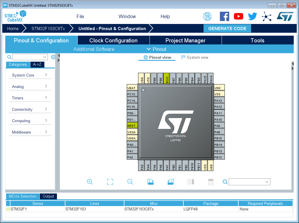
My plan is to use ye olde STM HAL and FreeRTOS for the base system. This is doable on the BluePill, and I've done so successfully with other projects, but it's not the most parsimonious approach with respect to systems resources (especially flash and ram). I'll have to keep an eye open for resource constraints as the project evolves. The BluePill has 'only' 64K flash and 20K RAM, which is tons if you're doing a cyclic executive (i.e. 'the big loop'), but that can get rapidly consumed by such abstractions as you use them more. Time will tell, and if I can get away with it, then I've saved a bunch of time.
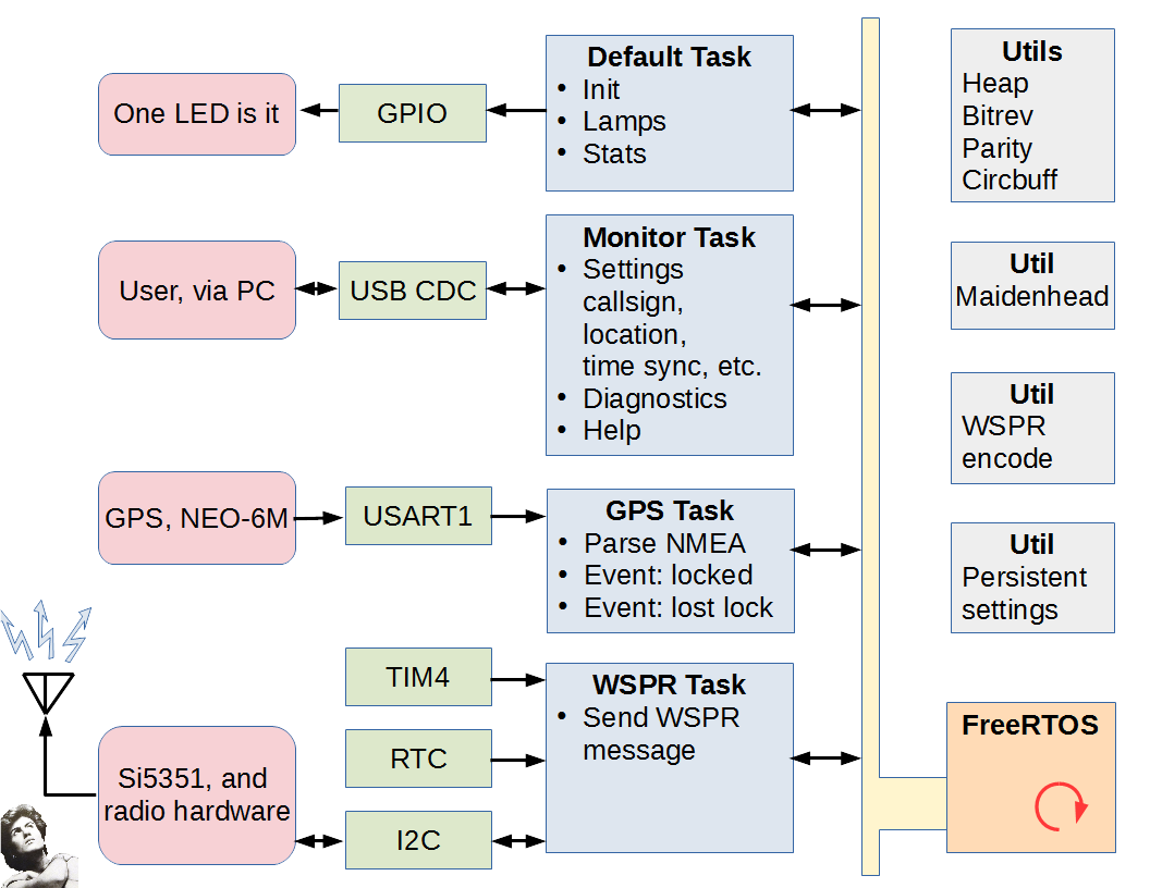
My current working theory looks like this:
![]()
(yes, I am a horrible diagrammer)
Broadly, the project will be created as four FreeRTOS 'tasks':
- the Default task
CubeMX will create a 'default' task when generating code. Due to the peculiarities of CubeMX's code generation system, I find it less trouble to just use the default task for something rather than try to delete it (because the next time you run CubeMX, it will regenerate it, or at least become confused). In this case, I use it to initialize and wire together the various sytems components, and then run in a loop managing UI and periodically collecting memory statistics.
The UI in this project consists of one whole LED. The 'management' of that LED is that there is a convenience function that allows one to light the LED for a specified period of time, so this task handles the expiration of that time period and extinguishing of the lamp. Blink patterns could also be supported here, but I don't plan on using blink patterns in this project at this time.
The periodic collection of memory statistics consists of watching the maximum stack usage of each of the tasks, the maximum and minimum usage of transmit and receive buffers, the heap utilization, etc. These statistics are useful during development for tuning various memory allotments. At release time they are not particularly useful, since tuning should then be complete. - the Monitor task
This provides an interactive command line interface over an I/O stream. (I still call these things a 'monitor' just out of old habit. Maybe I should call it a CLI or something more '90s-era.) I generally make this facility operate over a stream abstraction of my own construction because then it is trivial to bind it to any serial port, network (or even SPI in a pinch I suppose). Here is it planned to be on the USB providing the CDC class.
There are a few persistent settings that need to be made, such as your call sign, and also I do want to support running the project without GPS. That will mean needing to set/sync the clock explicitly, and providing location (either lat/lon or maidenhead). Probably serial port parameters as well, in case for some reason one wants to use a different speed to the GPS. The one I have selected used 9600 bps as default out-of-box, but I know others use 4800.
'Help' is a baseline command.
Additional features useful during development are diagnostics, such as dumping the memory usage stats collected in the 'default' task, and also a generic hex dump of arbitrary memory locations. - the GPS task
This handles the incoming data from the GPS module, parsing the sentences, and acting upon the received data. In this project, we are specifically looking for lock/loss-of-lock events, the lat/long location, and the time. These are used to set some global quantities and stimulate notifications to other processes which will handle them in their own ways. (E.g., the WSPR task will need to know if it should be transmitting based upon there being sufficient information to do so, namely location is valid and clock is valid.) - the WSPR task
This is the value of the project. The WSPR task handles the scheduling of outgoing transmissions, and the shifting out of the bits into the direct-digital-synthesis module.
The implementation of the tasks are supported by a bunch of Utility modules. There are a bunch of utils I have created and re-use in various projects which provide things like an I/O stream abstraction, circular buffers, table-based computation of parity, bit reversals, etc. Additionally, for this project there are some new utilities such as converting a lat/long into a maidenhead grid locator value, and encoding a WSPR message into a buffer suitable for directly shifting out via modulator.
One other that I commonly use, but which is ultimately project-specific, is a 'persistent settings' feature. This simply stores a C-style struct into the last page of flash. And elementary form of wear-leveling is performed.
The tasks are expected to communicate with each other via Inter-Process Communications facilities provided by FreeRTOS. There are several to choose from, but I usually go for the 'task notification' feature. This is a FreeRTOS-specific concept, and essentially it is a bitfield that you can set and cause the task to wakeup and take action upon the change. I like this feature because it is lightweight on resources. But other mechanisms such as semaphores and message queues exist as well if you need them.
There are various on-chip peripherals that are used by the tasks. There is only one LED on this board, and I don't plan on adding any other physical UI. That LED is controlled via a GPIO pin, and is managed by the Default task.
The Monitor task presumes an I/O stream abstraction, and so is hardware-agnostic, but the init activities of the Default task will bind the Monitor to the USB CDC stream. Similarly, the GPS task will be bound to the UART1 stream.
The WSPR task interacts with several peripheral resources.
- The TIM4 will be used for generic one-shot precision timing. These timing events will be used to shift out the bits of the currently transmitted WSPR message to the modulator.
- The RTC will be used to generate an Alarm interrupt event. This event will be used to schedule the start of transmission.
- The I2C is the mechanism used to control the Si5351A clock chip that we are using as a DDS synthesizer.
There are just a couple pieces of external hardware:
- the on board LED. 'nuff said here.
- the ublox NEO-6M GPS module connected to the USART1 resource.
- the Si5351 breakout board connected to the I2C1 resource.
- the RF section. I plan for this section to be very simple. The goal of WSPR is to transmit Weak Signals (or 'QRP' in ham jargon), so I do not plan on providing a power amplifier. But we'll see. However, the Si5351S is really a clock signal generator more than a DDS, and it outputs square waves. There needs to be thorough filtering of the harmonics in order to be legal. I plan to use some sort of passive filer/matching network for this part. I haven't really figured it out yet, but for starters I will probably support one band -- probably 20m -- and have a single low-pass filter for such. After that works, then I'll think about how best I can support multiple bands. Everything in this project except for this final filtering stage is capable of multiple band operation.
Next
Implementing infrastructure and the Default task.
- the Default task
-
Setting up the Build Environment
08/03/2019 at 19:48 • 0 commentsSummary
The various software tools were collected and deployed into a build virtual machine. A simple build was performed as a sanity check of the tools.
Deets
I generally use virtual machines for my project build systems. This make it easy to move around and archive, and to have a project-focused build machine. It also insulates me a bit from catastrophic systems failures that seem to happen every few years or so, because I can simply copy the virtual machine to the new system and carry on, instead of having to go through the Hell of installing stuff.
That being said, I am using a Windows virtual machine with VMWare Workstation. I haven't ever tried deploying these tools to a Linux system. It used to be the case that the chip manufacturers' development tools were rarely available on Linux, and you really had to be dedicated to get stuff working there, and so I have just always stuck with Windows in the interest of working on the project at hand rather that working on building ARM toolchains, trying to get device drivers to work, and trying to runs other Windows-only tools from the manufacturer. So Windows isn't free. And neither is VMWare. But it's a new era, and I think the STM tools might work on Linux. Similarly, you probably can get Oracle Virtual Box to work, too, if you want to have a build VM as I do. But you're on your own in figuring out how to do that. My only advice with Oracle Virtual Box is that I think you have to download and install an 'add-on' that give you the USB support. You will need the USB support to connect to the device programmer (and the USB of the BluePill if you want that, too).
The ST Microelectronics web site has all those tools for free download ('free' for the cost of registering yet another 'account' in some vendor's system). You will need:
- STM32CubeMX
This is a project configurator tool. You select your chip, configure the pins for the functions that you want, and it will emit a project replete with all the peripheral config code set up and the required peripheral libraries copied into project directory. Perhaps the most important part is the clock configuration. That chore is manageable on a simple chip like the the STM32F103 on the Blue Pill, but it's byzantine on a more complicated one like the 'F476. This tool also provides a few 3rd Party things, like FreeRTOS. - System Workbench for STM32
This is an Eclipse-based IDE. Yes, Java, my least favorite thing in the world. A third party ('AC6') packaged up the Eclipse with the gcc tools for ARM and OpenOCD for the programmer/debugger interface. I find that packaging very convenient, so I hold my nose with the Java and its glacial performance and Eclipse's glitchiness. - STM32 ST-Link Utility
This is not strictly required, but I find it convenient from time-to-time to do things like erase a chip, or dump it's contents. In particular, many of the Blue Pills come with a bootloader for Arduino stuff pre-loaded. The System Workbench doesn't know what to do about that. It's easiest to erase the chip with the ST-Link Utility separately once beforehand. Also, it is handy for proving that you have you ST-Link working with your board correctly separately of all the other myriad tools. If you cannot connect to your board with ST-Link Utility, the other stuff is not going to work, either. - STM CDC Drivers
If you're using an older Windows (as I am) you will need the CDC drivers. You won't need them straight-away, but later when a serial console is added over the USB port, these will be needed. If you're on Windows 10, you don't need to do this step because the stock driver will work.
Toys have arrived:
![]()
The blue board is the 'Blue Pill': the STM32F103C8T6 board ('Minimum System Development Board' as eBay vendors often call it). It's scarcely more than a breakout board itself. The violet board is Si5351A breakout board; it comes with some SMA connectors for the clock outputs if you want them (the clocks are also on the pin header). The golden dongle is a Chinese clone of the ST-Link v2 (and not a 2.1, this can matter when setting up with external tools, but this distinction doesn't matter here). It is not as full-featured as the actual ST-Link from STMicroelectronics -- it is only oriented towards SWD development (i.e. no JTAG), but that is fine and mostly a convenience, anyway.
Time to play...
Phase I -- Proving Connectivity with the Board
The first thing is to prove the ST-Link and Blue Pill are working together. This requires wiring some of the pins of the ST-Link to the pins on the end of the Blue Pill. It's useful to note that the debugging interface is SWD (an STM thing; similar in function to JTAG, but not JTAG), and moreover it does not bring out NRST. This has consequences later. (Strictly, NRST is brought out on one of the header pins, and you can use it if you want, but you don't have to do that if you make a configuration change in the IDE that I will describe later.)
The pins on the Blue Pill are Gnd, SWCK, SWDIO, and 3.3V. These need to be wired to matching pins on the ST-Link. If you're using the cheap Chinese clone, the pinout is printed on the device.
![]()
One thing to keep in mind is that even though there is a 3.3v connection over this set of pins, this is not for powering the board. Rather, it is so the ST-Link can monitor the Vcc of the board. You need to power the board separately, and that typically means plugging a USB into the Blue Pill and putting the other end... somewhere. It can be a port on your computer, or one of those cell phone chargers. Later, it is useful for it to be the computer, because we'll set up some USB functionality on it, but for now we just need it for power.
If you are using a virtual machine (as I am), you will possibly have to explicitly 'connect' the USB device to the virtual machine to make it available to the software running therein. The name of the device is 'STMicroelectronics STM32 STLink'.
Some Blue Pill boards come with a bootloader application that is handy for Arduino, but is problemattic for us. If the Blue Pill enumerates when you plug the USB in, chances are that it has the bootloader on it. If you use 'device manager' and see something like "Maple 003", then that is the boot loader.
When you have this bootloader, the ST-Link will not be able to erase the device. Attempting to do so will result in this message:
![]()
What must first be done is to erase the readout protection bit (which will also cause the entire flash to be erased). This is done via 'Target', 'Option Bytes...', which will probably initially look like this:
![]()
You will need to change the 'Read Out Protection' to 'Disabled'.
![]()
Then you can 'Apply', which will remove that protection (and also erase the device). Now you have revirginated your Blue Pill, and it should be usable with the System Workbench for STM32 (i.e. Eclipse). You probably will not need ST-Link Utility anymore, but I keep it around.
Phase II -- Creating a Project
As mentioned, I use the STM32CubeMX to create my initial projects (and later tweak them, as invariably you will). The gist of this activity is configuring all the peripherals, pin assignments, clock sources, etc., for the chosen chip. For complicated development boards with a lot of external peripherals, this can be a little chore, so I keep baseline CubeMX project definitions on-hand for reuse. I just copy and rename the file (the extension for the CubeMX definition is '.ioc') as appropriate for the new project. The Blue Pill is a simple board, so it's not too much work to create one from scratch, but it's still handy to have the baseline one to start with.
The CubeMX is a Java application, so expect slowness. Starting it up will put you in a kind of 'wizard mode' where you step through teh selection process. We would be using the 'MCU Selector' and it is easiest to just type in the part name 'STM32F103C8', and then choose 'Start Project' to begin configuration. This will land you on a view of the chip with the various leads.
![]()
There is a separate page for clocks, on the 'Clock Configuration' tab, which show the default (which is how the chip powers up, with some on-chip low-speed RC oscillators):
![]()
Note that you are not allowed to specify the external crystals at this point. To do that you need to fiddle with some other stuff first.
There is a separate page for saving the 'project', on the 'Project Manager' tab:
![]()
The 'Project Name' will become the filename that will be saved. The 'Project Location' will be where it will be saved, and that should be an empty directory at this point, because there will be a lot of stuff spewed into it later.
The most critical thing is the 'Toolchain/IDE', which should be set to 'SW4STM32', and 'generate under root' select. This will cause generated code to be suitable for the System Workbench for STM32 (i.e. Eclipse). I would go ahead and save that now.
One peripheral we will be wanting is the debugger port (SWD or JTAG, but we will be using SWD for the Blue Pill). That is under the 'Pins & Configuration' tab, and on the left under 'System Core', and there is 'SYS', and double-clicking that should make a config pane fly out, and on it there is 'Debug' which should be set to 'Serial Wire'. That will make the SWD port wired to the ST-Link active.
There is a 'Generate Code' button that you press to cause the project to be emitted. Go ahead and do that, and launch the IDE.
The first time you run System Workbench (i.e. Eclipse) it will want you to specify a 'workspace'. This is just a working directory where a bunch of temporary files per-project are kept. I keep a directory named 'workspace' and just let it always use that -- you can have a bunch of project that use the same workspace; stuff will be kept separate therein.
At this point there is a do-nothing application generated that will build and run. This is a useful time to get the ST-Link stuff setup so you can debug. There is a little trick to this with the Blue Pill because the NRST pin is not connected to the ST-Link, and the default is to expect that it is. However, there is nothing to edit yet because System Workbench has not generated any configs to edit yet. So, use the hammer button to 'build' first. This should build to completion because all this is wizard-generated code. After you have build, then we can start fixing things. First, there is a bug button that is used to start in the debugger, but don't press it. Rather, use the drop-down arrow next to it to present options. Here we want to choose 'Debug As' and 'Ac6 STM32 C/C++ Application'. /This/ will cause Eclipse to generate some stuff we will subsequently edit. What will actually happen, though, is that we will get an error message. It might be the cryptic 'failure in launch sequence', or maybe something slightly improved by now, but that's OK. What it will (or should, if we're on the same page) be failing for is simply that the chip can't be reset.
After that fails the first, we'll be in a position to fix it. Now under the same bug button dropdown, select 'Debug Configurations...' and you will be presented a dialog that has an entry for this project's debug configuration:
![]()
Critically, on the 'Debugger' tab is a button 'Show generator options...'. The settings we need are buried under there, so click it to expand stuff.
Under 'Mode Setup', the 'Reset Mode' must be changed to 'Software system reset'.
![]()
This means that the IDE will reset the chip via a SWD command rather than via twiddling the NRST line (which is not connected). This is the key. You can 'Apply' these changes, and close. Now if you click the bug button, it should connect successfully, erase the device, load the new firmware, and start running it. If you have not changed anything else, it should also immediately stop at the beginning of main(), so you can also single step. Single-stepping can be a very slow process over SWD and in Eclipse, so be patient.
Once this has been done successfully, you're off to the races. One last thing I recommend changing, though, is the fact that the IDE automatically creates a breakpoint at the start of main(). This annoys me, because I rarely want one there, and because breakpoints are a limited hardware resource and this uses one up. You can fix that in the same 'Debug Configurations...' dialog we just used.
On the 'Startup' tab, there is an option under 'Runtime Options' labeled 'Set Breakpoint at:' and an edit control with the text 'main' in it. This is what controls that automatically created breakpoint, and I deselect it. If I want a breakpoint at the start of main (I rarely do), I will explicitly set it myself.
With that sanity check out of the way, we can start to finish setting up the CubeMX project. Close System Workbench for now, and start CubeMX up (possibly by double-clicking the *.ioc file).
Phase III -- Finishing Up the Generic Project Definition
Earlier, we were not able to set the clocks for this board, because we hadn't configured the clock peripheral. On the 'Pinout & Configuration' tab, on the left, are some 'categories' of things we need to set up. In particular, under 'System Core' is 'RCC' which is the chips clock generation subsystem. If you double-click it, a pane will fly out with options. In particular, the 'High Speed Clock' (i.e. the 8 MHz crystal) and the 'Low Speed Clock' (i.e. the 32.768 KHz watch crystal) will be 'disabled'.
![]()
You'll want to set those to 'Crystal/Ceramic Resonator'. Doing so will now make it possible to make changes on the 'Clock Configuration' page! You can key in the frequency (8 MHz in this case), and select various multiplexer options to direct the clocks to the sources you want and fiddle with the speeds delivered to various subsystems. There is a 'Resolve Clock Issues' button that will help figure out what the prescalers and PLL values should be to achieve the speeds you select. Because I am running this project off external power, I set all those speeds to the maximum.
![]()
Then you'll go back to the 'Pinout & Configuration' and set up other stuff. For the 'baseline' project for the Blue Pill, I set the 'System Core', 'SYS' component to specify 'Debug' as 'Serial Wire', and also set 'Connectivity', 'USB' to select 'Device (FS)'.
Additionally, I configured a few pins: PA10, left click, select GPIO_Input (for now). Right click, select 'User Label' and change the name to 'BOOT_RX'. It is actually a UART that the on-chip bootloader (not the one we erased, this is from ST). I did similar for PA9, select GPIO_Output and naming it 'BOOT_TX'. I also changed PB2 to GPIO_input and named it 'BOOT1', and PC13 to GPIO_output named 'LED_D2'.
This should complete the things that are provided on the dev board. You might need to visit the Clock Configuration to make sure all the clocks are still OK after having fiddled with peripherals. You can then 'Generate Code' again. This will overwrite what was previously generated, and emit new setup for the peripherals that were added.
When re-generating code, the CubeMX avoids destroying your code if it is between protected regions demarcated by some special comments. The comments start like:
/* USER CODE BEGIN Includes */and end like
/* USER CODE END Includes */The specific name of the region will be different in different places. These comment blocks should not be altered or CubeMX will get very confused. Also, you cannot create your own 'USER CODE' blocks -- you have to use what CubeMX provides.
When I get all that stuff tweaked for the development board as it is out-of-box, I then archive the *.ioc for future projects with that board (you can discard all the other files -- they aren't archival). I do further tweaking on a project-by-project basis depending on the project's needs.
Phase IV -- Making the Project Specific Definition
Having made a copy for my new project, I then start tweaking stuff for the new peripherals I am goign to support. In this simple project, there's just a few:
- The UART1 will be used to receive data from the GPS.
- The I2C1 will be used to control the Si5351 chip.
- The USB will be set to the CDC profile.
- We will use FreeRTOS.
- Due to a quirk, we will set the system tick to be TIM2.
To start, I first setup the pins. Many of the peripherals have alternative pins that can be used for the same functions, so I find that specifying which pin before configuring the peripheral function results in less wasted effort than the reverse. The BOOT_RX (on PA10) needs to be changed to 'USART1_RX', and I change the label to 'GPS_RX'. The label makes it easier to read, but it also causes a #define to be emitted so it becomes a symbolic constant in your code. As such, the label names must be C language compatible identifiers. Similarly, I change PA9 to be 'USART1_TX' and labeled 'GPS_TX'.
PB9 becomes 'I2C1_SDA' and is labeled 'SI5351_SDA', and PB8 becomes 'I2C1_SCL' and is labeled 'SI5351_SCL'. That should be it for pin function specifications, now we have to tweak the peripheral settings.
Under the Categories 'Connectivity', the 'I2C1' configuration (double-click on 'I2C1' if needed to make the pane fly out), the I2C mode should be 'I2C' and below there is 'Configuration' with several tabs. In the 'Parameter Settings' tab there is 'Master Features', and 'I2C Mode' should be set to 'Fast Mode'. On the NVIC Settings I enabled both interrupt sources.
Similarly, under Categories 'Connectivity', the 'USART1' configuration, the Mode should be Asynchronous, Hardware Flow Control set to Disable, and the Parameter Settings Basic Parameters should specify 9600N81 since that is what the GPS module comes up as. On the NVIC Settings I enable the USART1 global interrupt.
Under the Categories 'Middleware' there is 'USB_DEVICE'. We can specify 'Communication Device Class' (under 'Mode').
Also under 'Middleware' is 'FREERTOS'. We should use Mode, Interface, CMSIS_V1 for compatibility with other generated code. There are a boatload of other options to tweak FreeRTOS's configuration -- you'll have to look at the documentation to see what all those do.
A quirk of running FreeRTOS on the CubeMX-generated project is the HAL libraries from STM want to use the SysTick timer for their own purposes. FreeRTOS by default wants to use it for the scheduler (that's what it intended for). CubeMX knows this and will issue a warning, but what you need to do is go to Categories, System Core, SYS, as set 'Timebase Source' to something /other/ than SysTick. I generally select 'TIM2'. This change will cause FreeRTOS to use Timer 2 for the scheduler instead, and the HAL libraries can then continue on in their assumption that SysTick is something they can use freely.
You might need to check the Clock Configuration to make sure that no issues arose, but they probably didn't.
Now you can Generate Code to make the boilerplate for the project. If you are creating this from scratch (i.e. you deleted all the prior stuff), you will need to go through the 'Debugger' setup steps again. Those choices are stored in the Eclipse project definition.
Next
Project Architecture
- STM32CubeMX
-
Plans Within Plans
08/02/2019 at 15:27 • 0 commentsSummary
I've decided to make the WSPR beacon using a 'Blue Pill', a Si5351A breakout board, and a ublox NEO-6M module.
Deets
The major goal of this project was simply to get familiar with the Si5351 synthesizer chip which I had planned to use in another project (which may or may not ever happen), and I had a 'breakout board' for such on hand. They can be had for about USD $5 on eBay from China if you're willing to wait, or domestically for upwards of USD $10. This synthesizer is quite popular, but it has 188 registers (in the full 8-channel version) that have to be set up to get it to output signals. There are some decent libraries out on the web, though I didn't find decent non-GPL ones, so I'm probably going to hand-roll a bespoke one for my purposes.
Part of the nature of the WSPR protocol is to include the location from which the beacon is transmitting. This could be configured in, and that's viable for a stationary beacon, but I wanted this one to be self-configuring and deployable ad-hoc in the field. So I decided to add a GPS module to it since those are so cheap now. In this case I elected the apparently popular ublox NEO-6M module.
Another part of the nature of the WSPR protocol is the requirement of being timely. It is necessary to have the beacon synchronized within one second of UTC. Transmissions are done in an 'aloha' fashion on designated bands at the start of an even-numbered minute. The transmission time is nearly two minutes in duration. I'm not exactly sure why this requirement exists, but maybe it is in hopes of being more orderly and thereby reducing the likelihood of folks stepping on top of each other, since the beacon network otherwise operates asynchronously. In this case the GPS module serves double-duty, because it can also set the clock to the true UTC time automatically.
Since this seemed like a fairly simple project, I decided to give the Blue Pill a whirl. These boards are so cheap -- about USD $3 from China -- that I try to keep a plurality of them on hand always for random projects like this.
Since I'm using the Blue Pill, I will also be using the toolchain from ST Microelectronics -- namely STM32CubeMX, STM32 Workbench, and STM32 ST-Link Utility. Oh, and a STM32 ST-Link (compatible) programmer. The programmer I am using at the moment is one of the cheap Chinese clones that can be had for about USD $5. If you need to get one of those specifically, consider also getting a USB extension cable as well, because that ST-Link has the USB Type A device connector on the body of the programmer, plugging directly into your computer (much like a USB memory stick). This doesn't give you much reach to your workbench to connect to the board, so you'll either need a USB extension cable or really long SWD wires to your board (which are typically unshielded ribbon wire).
And then of course all the jumper wires with the Dupont connectors of various genders. They're very handy for quick prototyping with these breakout modules. I used to think they were absurd -- when I was younger I would prototype with solder and self-etched PCBs -- but I have come to appreciate the freedom to plug stuff together ad-hoc in this modern, highly integrated, modular, world.
Most of these things I had on-hand, but I did need to order the GPS modules, and being a cheap bastard I ordered them from China to save a couple bucks (OK, really so that I could afford to buy more in case I blow them up -- I ordered 5). This means waiting for the slow boat to arrive.
Next
Setting up the development environment.
Careless WSPR
A desultorily executed Weak Signal Propagation Reporter beacon.