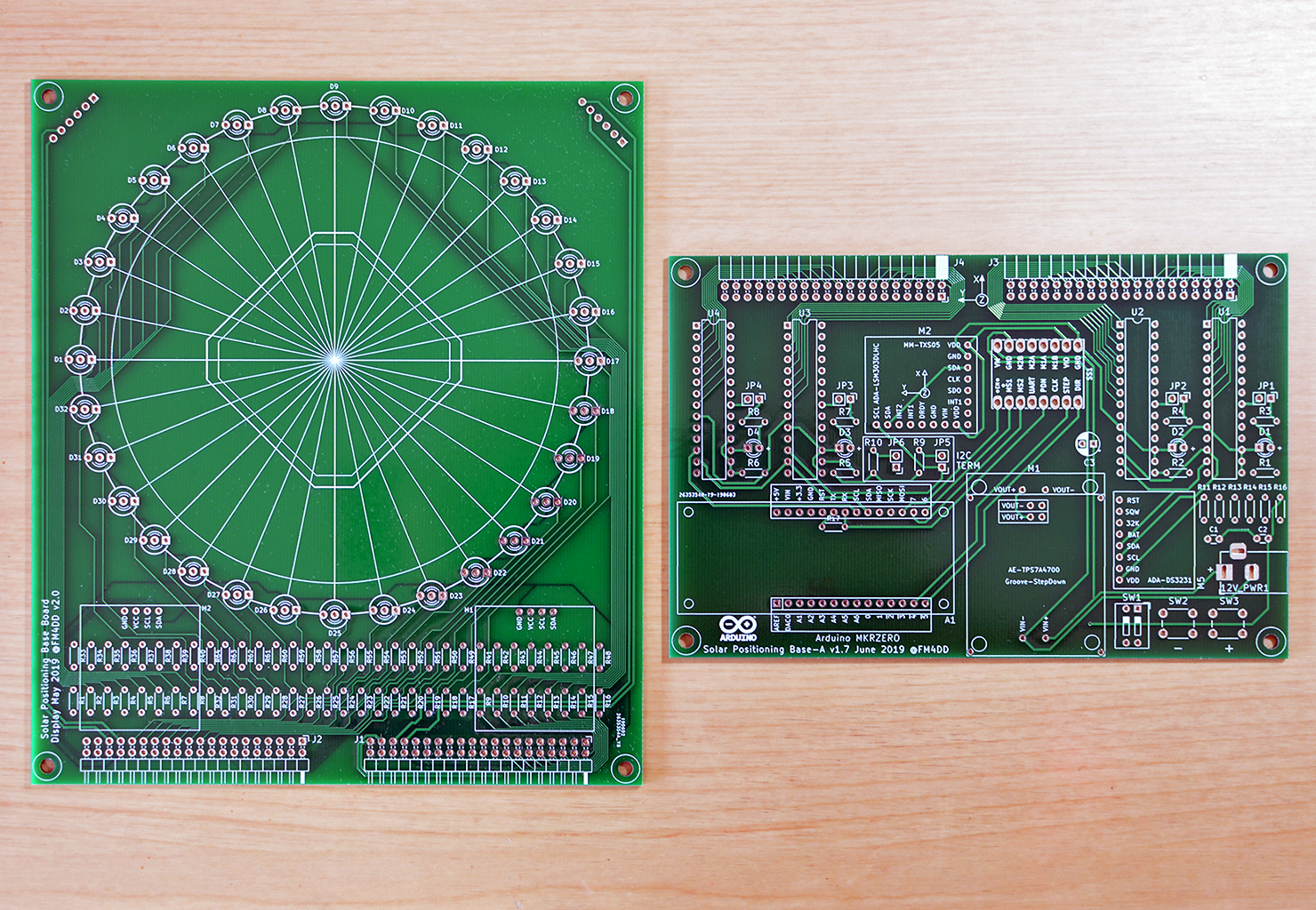
With Revision 3, the final shape starts to emerge. After becoming familiar with PCB production basics, it was time to turn the design into a device that can fully emulate and display the solar position.
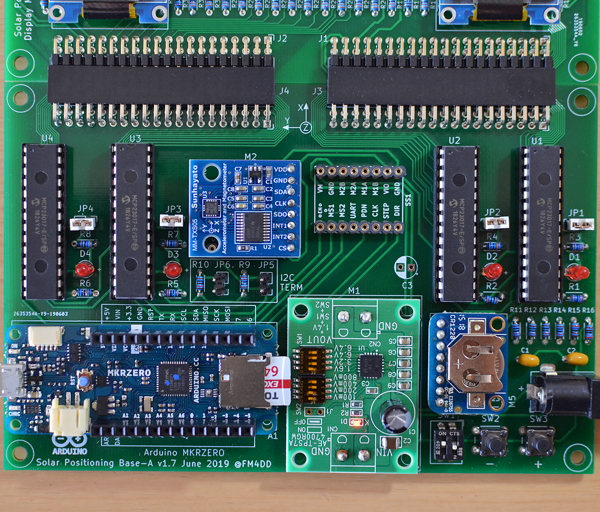
Expanding the displayboard to arrange the 32x LED set in a circle, and adding the stepper motor driver to the controller board meant moving the OLED display out to the display board. Adding the second OLED is not just for symmetry: showing the current azimuth angle in addition to the boards north heading adds to the convenience of quick data correlation. Here is the Revision 3 PCB set, consisting of mainboard v1.7 and matching displayboard v2.0. In the photo below, it shows the updated mainboard with the new stepstick connector fitted in the place of the previous OLED location. PCB design files (gerber), as well as the Arduino code are published in the revision 3 GitHub repository.


Adding the second OLED display to the I2C bus had an issue that required manually updating the u8g2 display library. I documented the solution in the GitHub issue tracker.
 Frank
Frank
Discussions
Become a Hackaday.io Member
Create an account to leave a comment. Already have an account? Log In.