This project builds a solar tracking device to align solar panels towards the sun for increased power output. These systems exist both commercial and in the maker space, but they are not very common. Today it is often cheaper to just increase the solar panel area. Solar tracking comes with a variety of challenges:
- Identify the location of the sun in the sky
- Determine if it is worth spending alignment energy to turn panels towards the sun
- Mechanical design and maintenance
For 1., identifying the suns location is typically done by either using multi-directional light sensors, picking out the brightest spot in the sky, or by doing location and time specific calculations, determining the sun position from the known path and rotation of our planet. The last method is providing insights about the angle distance required for solar panel alignment, and the reason I choose it as the main method.
For 2., moving and turning solar panels makes only sense if the received energy exceeds the energy that is being spend on tracking. Cloudy days, shallow angles, etc already diminish the energy generation, and solar tracking needs to find the fine balance and trade-off point to make it worthwhile.
Lastly, mechanical design and a robust longterm operation is another concern.
This project, Suntracker 2 Revision 3 focus is on point 1.
Design
Solar position tracking determines the suns location from a fixed locations observer point of view.
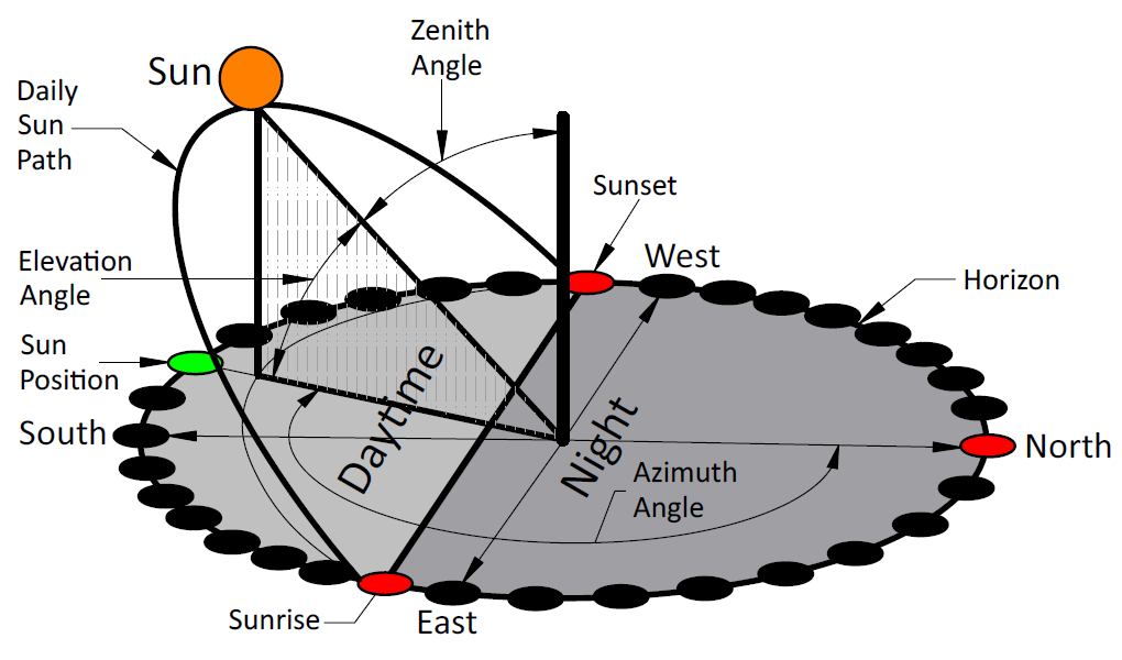
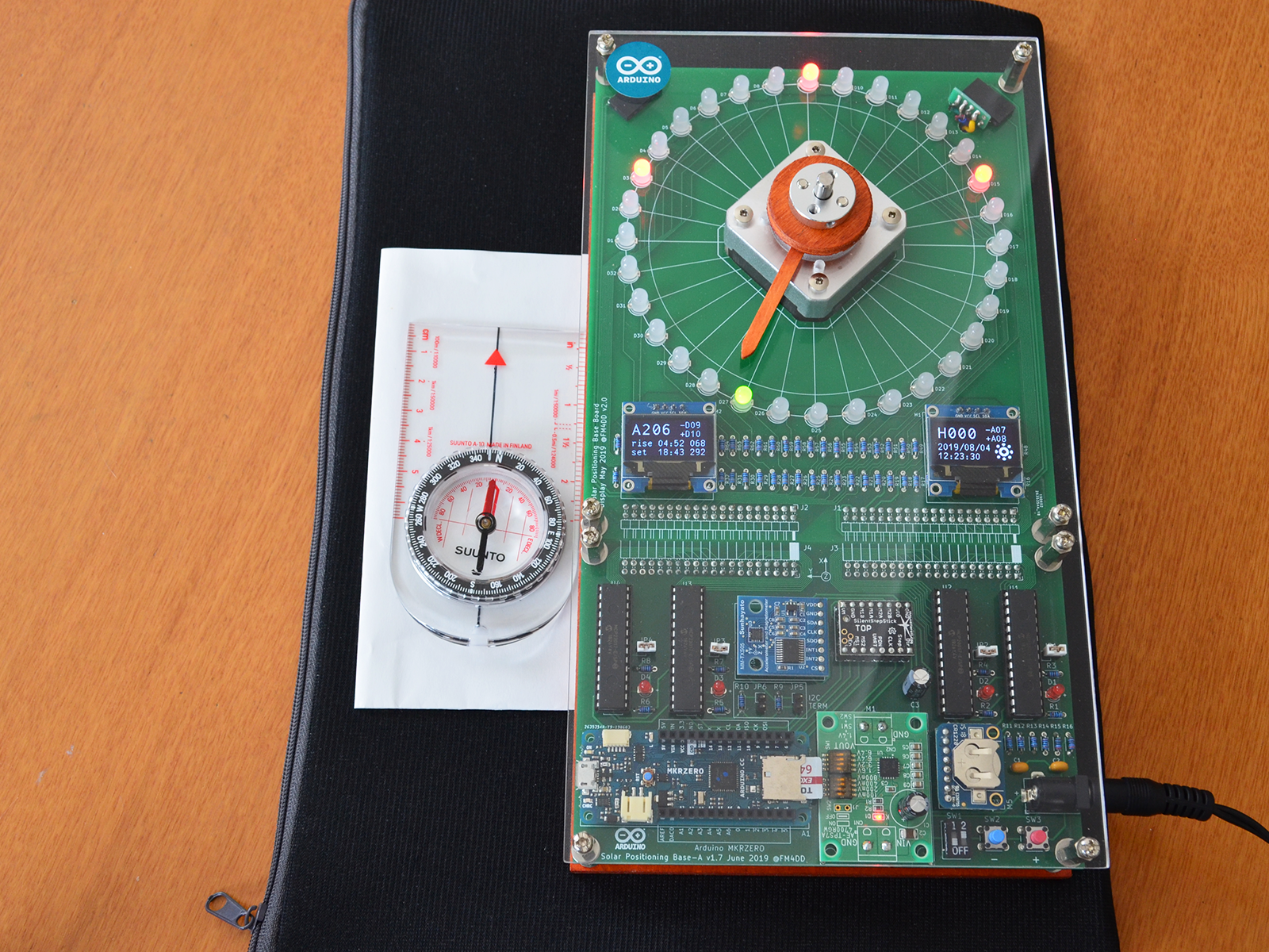
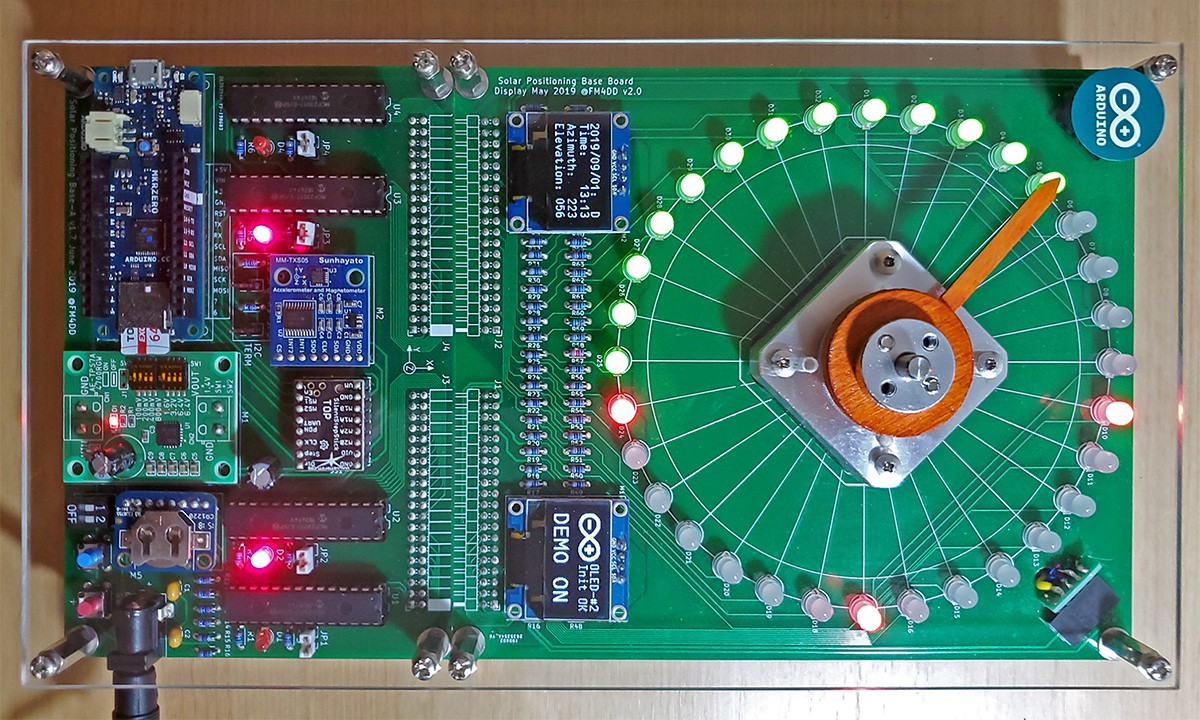
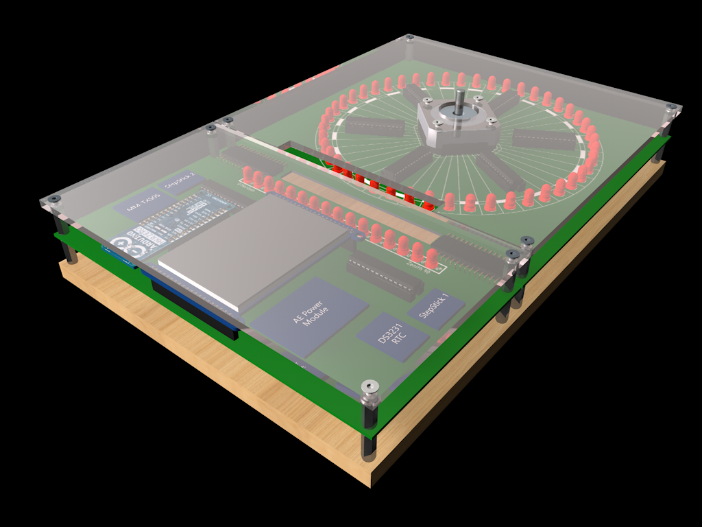
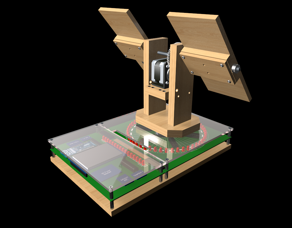
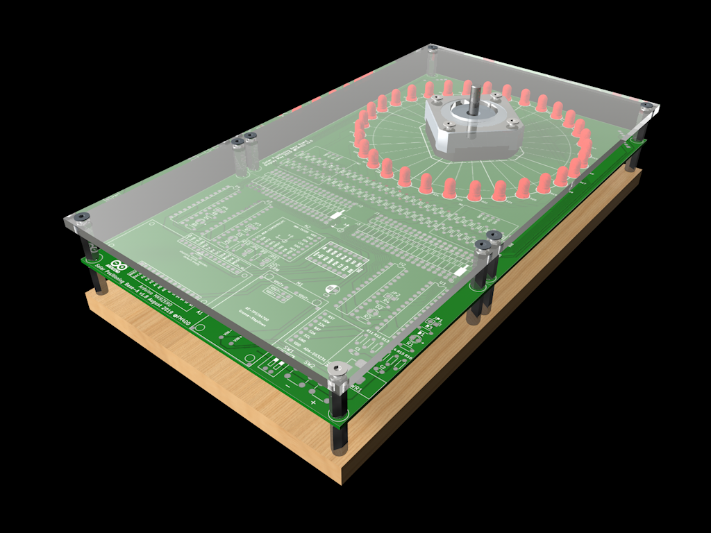
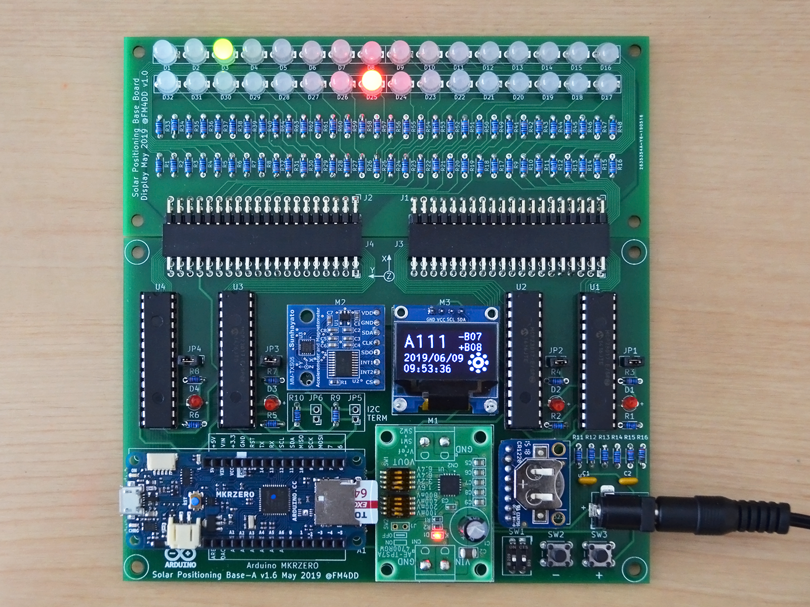
Suntracker 2 Revision 3 is a single axis tracker for the suns azimuth angle. Main feature is a dual-color LED circle that will display the sun location (green) in relation to north (red, center). Two more red LED will show the sunrise/sunset azimuth, which limit the range for daytime solar tracking.
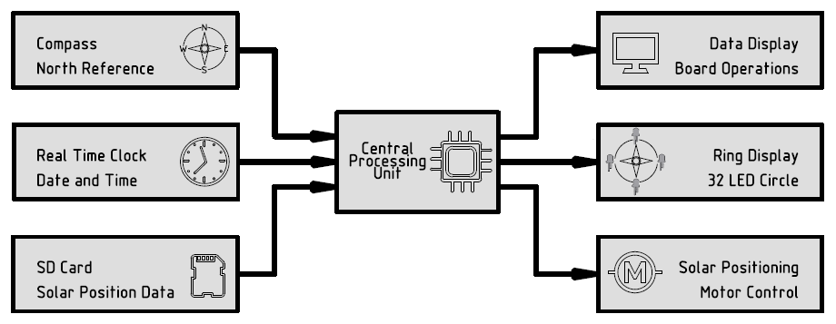
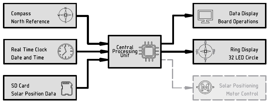
Suntracker 2 revision 3 determines the north heading with a magnetometer sensor, and compensates for the local magnetic north declination to determine true north. Combined with a real-time clock and a pre-generated set of solar positions stored on a MicroSD card, it displays the current sun position, and drives an optional Nema stepper motor to align with the actual sun position during daytime. The system is controlled through a 32bit ARM Cortex M0+ class microprocessor, the Arduino MKRZero.
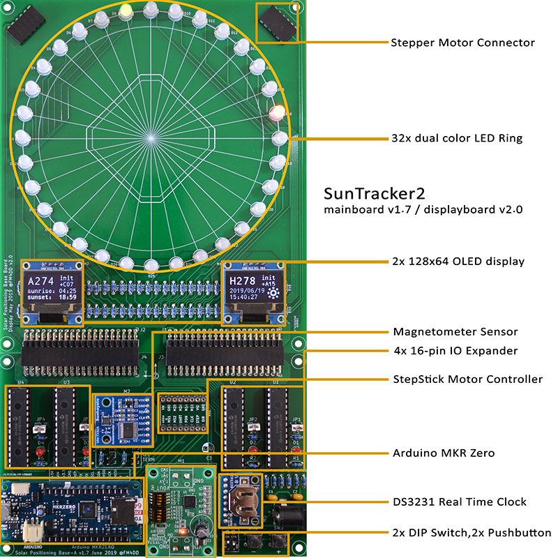
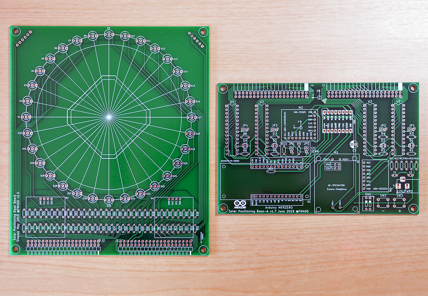
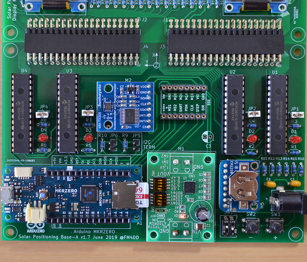
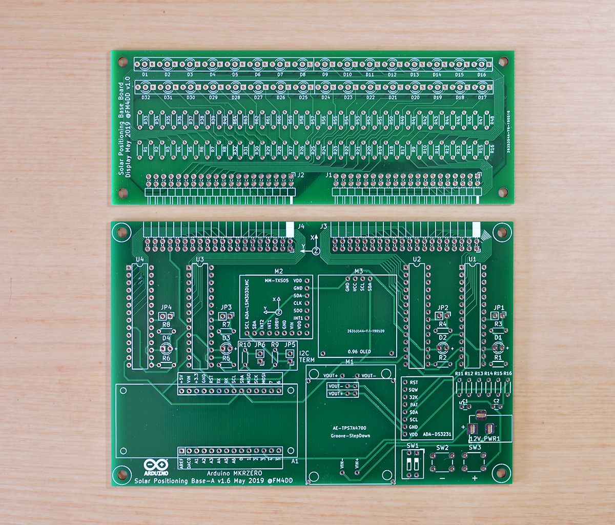
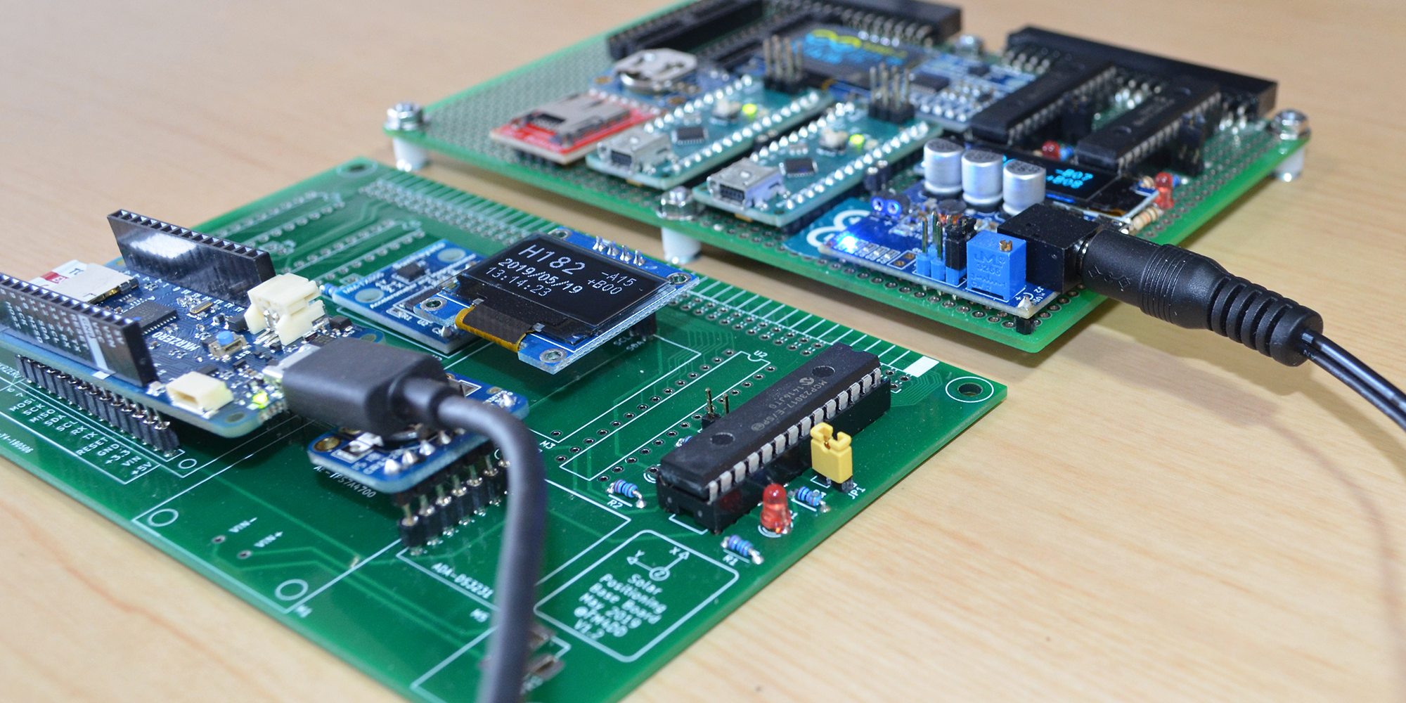
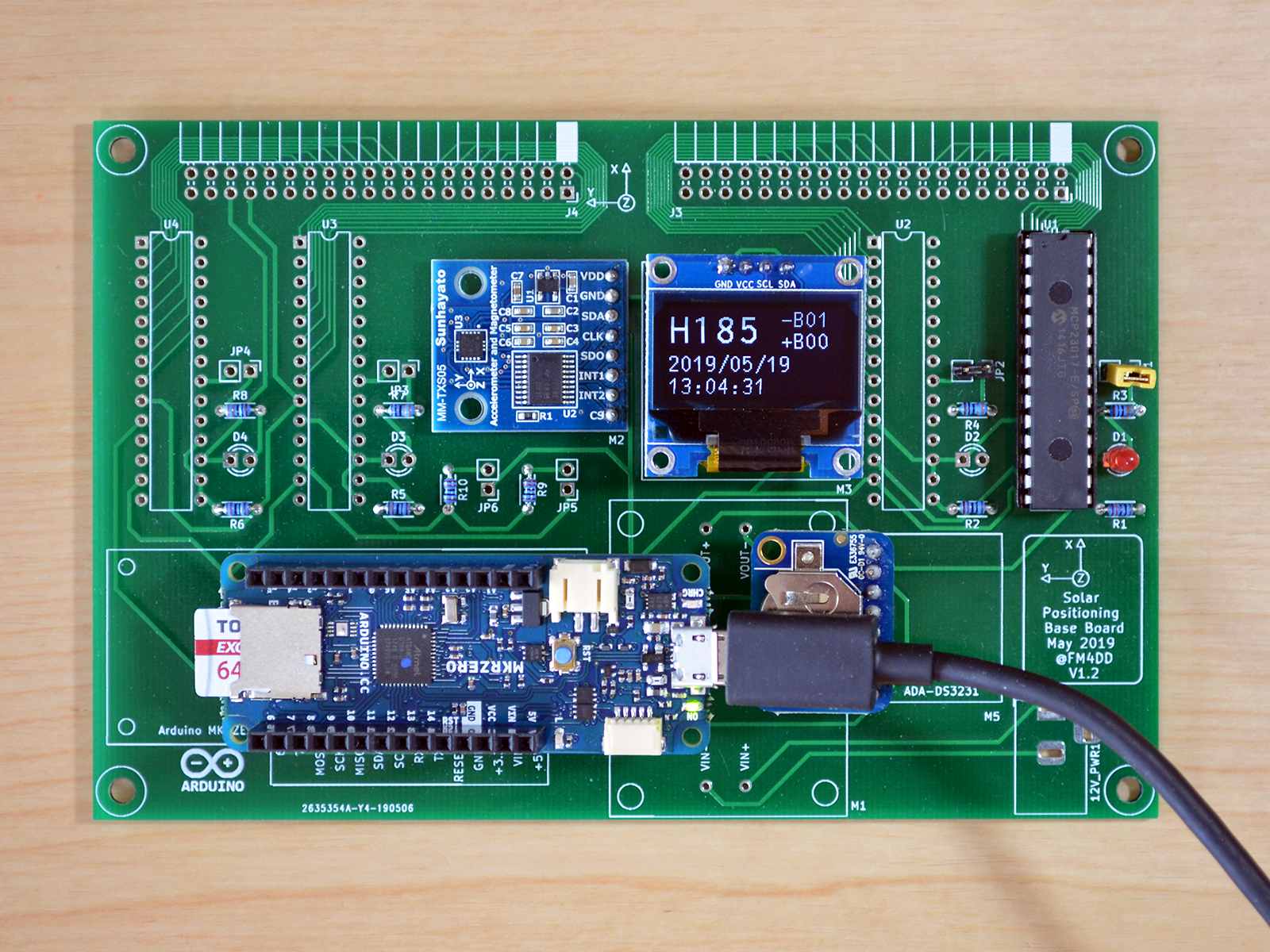
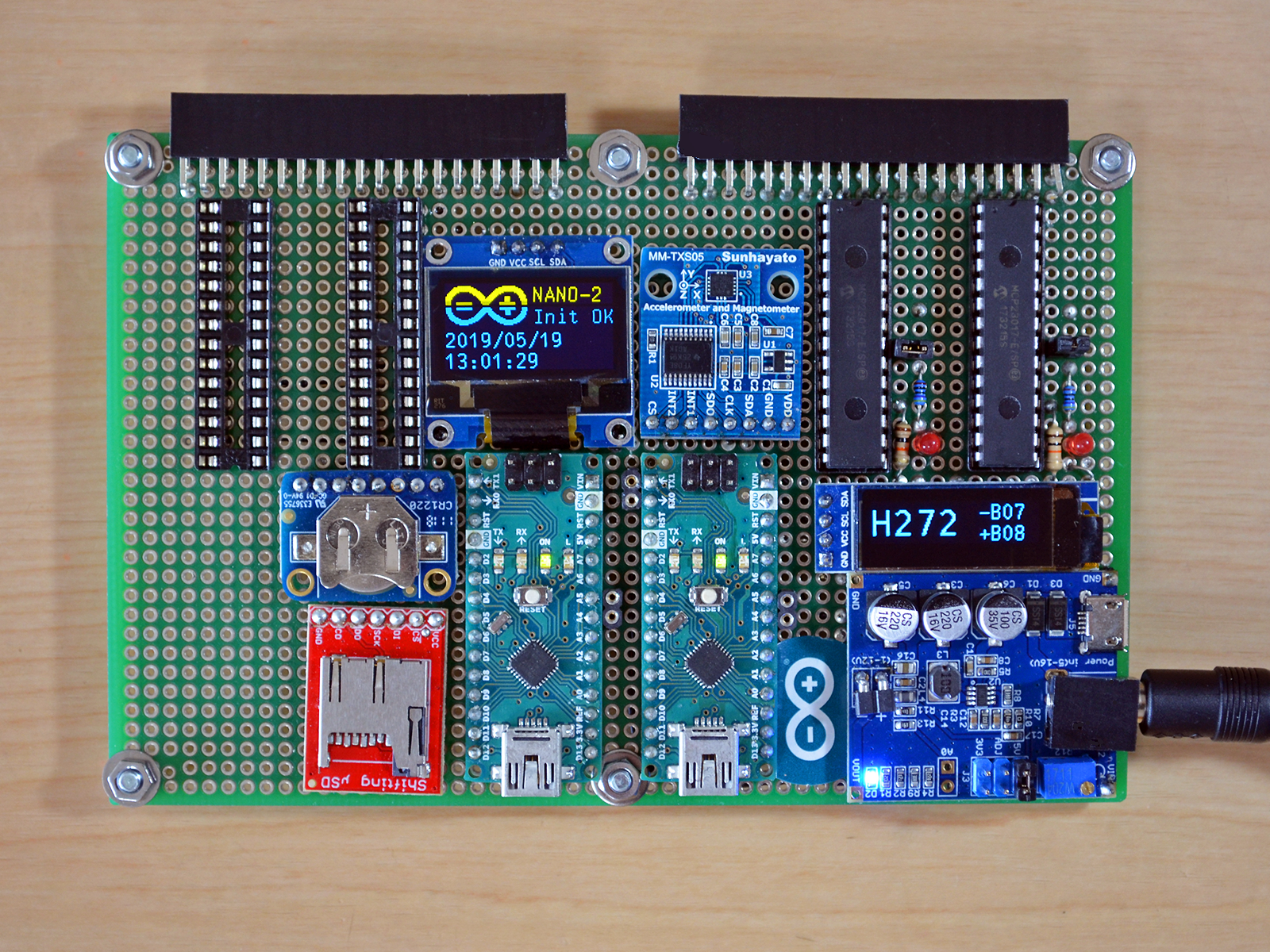
Board Layout & Components
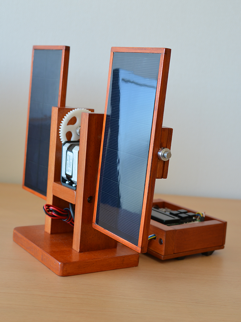
Final System
Visualization
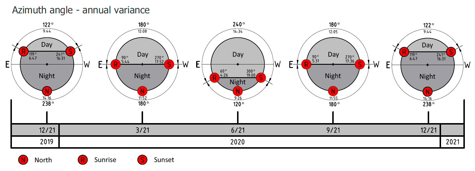
The projected azimuth tracking range for my location is shaping up as shown below. Knowing the suns angle range is crucial for urban areas, where shading, even if its only seasonal, can have a big effect on solar power generation. With the next Suntracker version I am planning to add a suitable TFT display to draw this data in real-time. Below is an approximation, in reality solstice and equinox dates are slightly off, depending on the location.
 Frank
Frank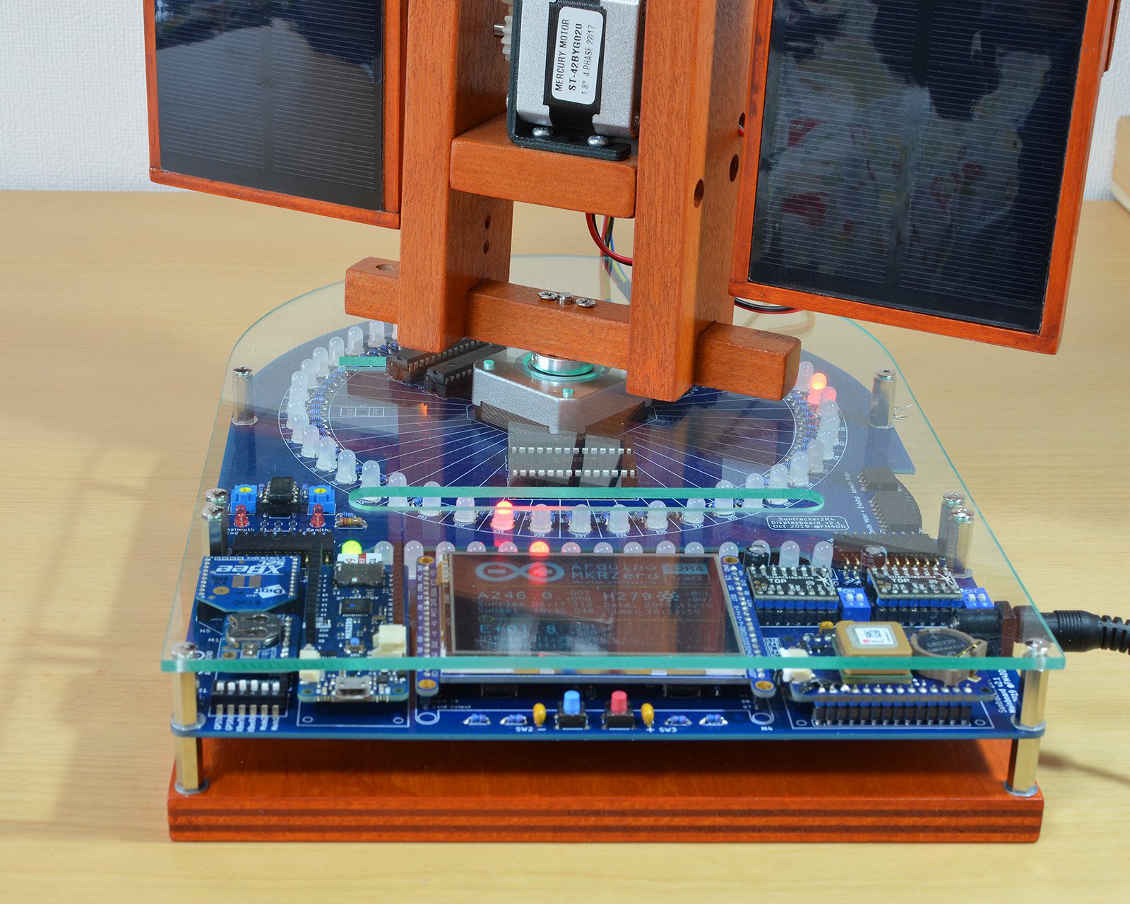




 rob
rob
 Thomas R
 Stephen Holdaway
Hi Frank,
Great project. I was inspired to give the Suntracker v2.3 a try and had some questions. The pcb and schematic for the bottom board call for a resistor "R17" however, this resistor is not in the components list (that I could find) and seems to be placed under or behind the arduino MKR Zero so it is not in any of the pictures. Am I missing something in the instructions or docs? What component is needed and how should it be placed?