-
Sun Tracker 2 Revision 4 - Dedicated Project
11/18/2019 at 10:38 • 0 commentsAfter 3 months work, Suntracker 2 Revision 4 is now coming alive in its separate, dedicated project log at https://hackaday.io/project/168507-suntracker-2-revision-4. While still not completely done yet, the newer, bigger, more complex version is coming into the final stages of assembly, coding and integration. Thanks for following this project! Cheers, Frank.
![]()
-
Sun Tracker 2 Revision 4 - Development
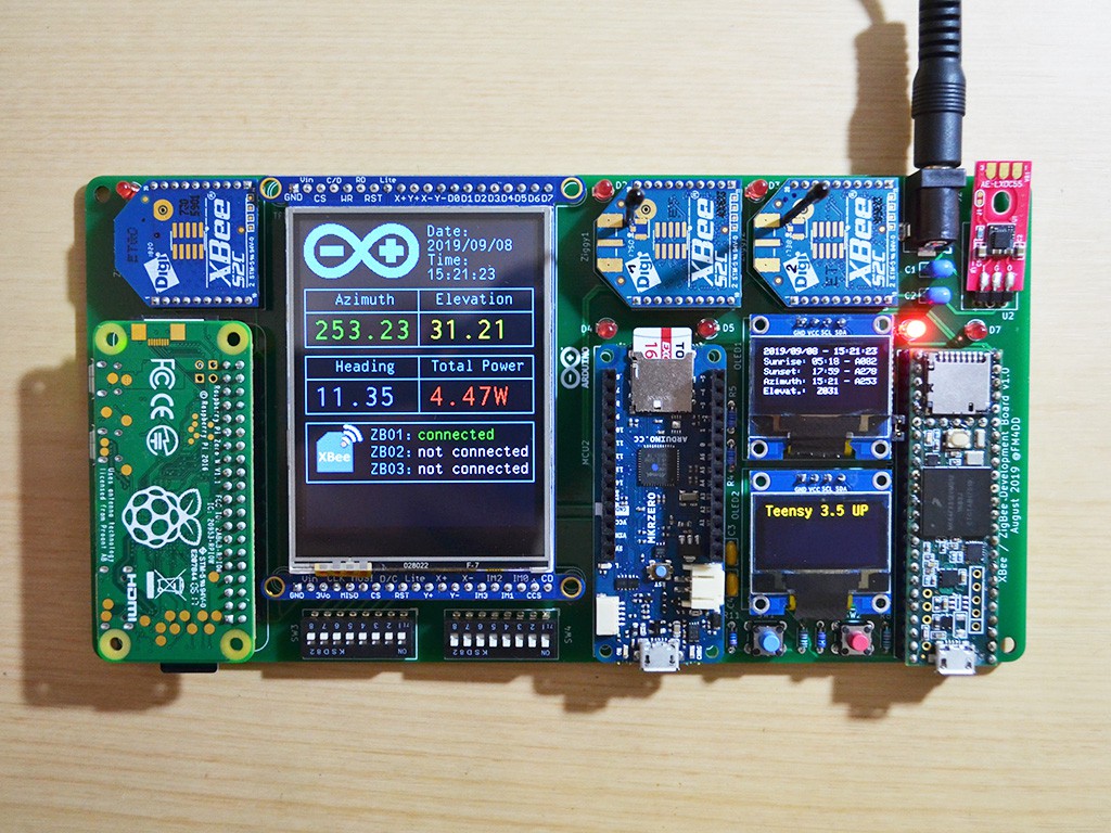
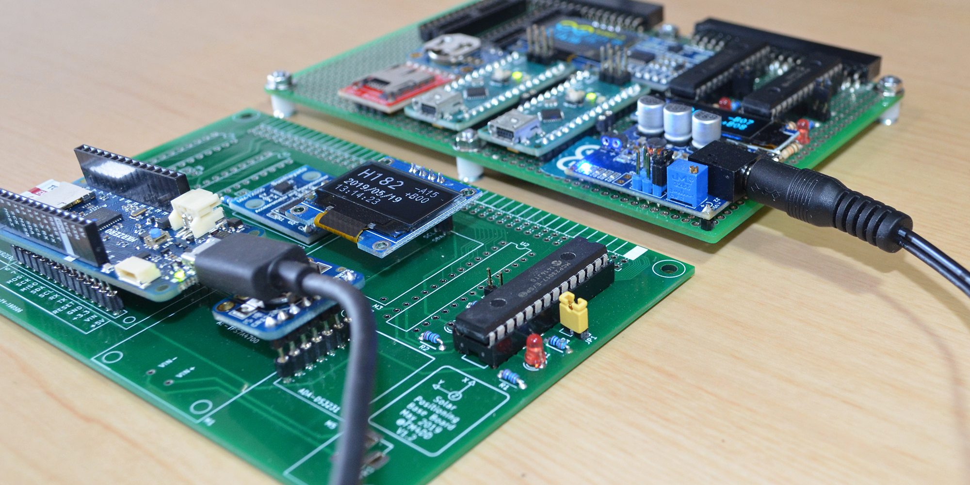
09/08/2019 at 16:20 • 0 commentsIt is tedious and time-consuming, but there is no shortcut around learning and getting experience with new hardware. For the next revisions there is a lot of new tech I want to adopt: I'd like to integrate a SPI-connected TFT screen, add wireless communication, and separate the controller functions to do onboard solar position calculations on a master controller. To support the development, I created below carrier board so I can work out the required code and exact pin assignments. It is built purely for hardware integration and code development.
The 2.8" TFT screen is already nicely working on the MKR Zero. Next, I'll switch the TFT over to the Raspberry Pi Zero, DIP switches can route the TFT display SPI signals to either side.
![]()
The XBee modules I haven't started yet. Three modules are to form a star network, each has a microcontroller attached to it: Raspberry Pi Zero W (left), Arduino MKR Zero (center), and Teensy 3.5 (right). Eventually, they should all talk to each other over the air. There are quite a number of competing wireless communication standards to choose from, I'd love to hear other experiences.
I have got long list of schema improvements accumulating with the increased complexity. The next Suntracker revisions will need some time to built, accommodating the learning curve.
-
Sun Tracker 2 Revision 3 - Software update
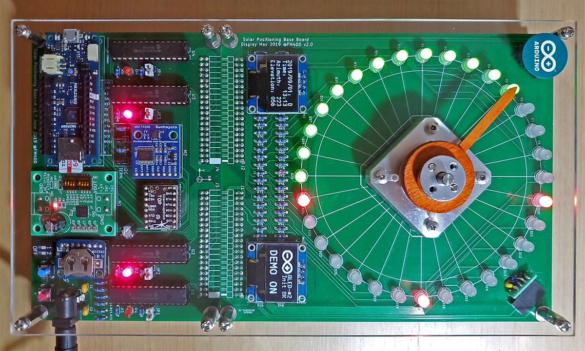
09/01/2019 at 11:38 • 0 commentsDuring daytime tracking, I wondered if the display could not just show the sun current position, but also the previous path that has been completed since sunrise. This would visualize the sun's progress. Below picture shows what I mean:
![]()
I wrote a new function called "display_mode2", which can be selected with DIP switch 1 in the "ON" position. The previous function of DIP-1, enabling the extended selfest, this function has been moved to push-button 2, which brings it up when pressed during power-up. The light path clears out with sunset, and during nighttime the sun just moves as a single green LED. Its not fully complete yet: the self-align movement of the tracker does not always clear out all LEDs of the light path. Its a bit more tricky to move a group of LEDs around the ring. I also want to let the leading daytime position LED blink in display_mode 2. These things need another quiet afternoon. Turning off DIP-1 returns to the original display mode.
The updated software sketch has been published to the projects github repository "src" folder.
-
Sun Tracker 2 Revision 4 - Design Phase
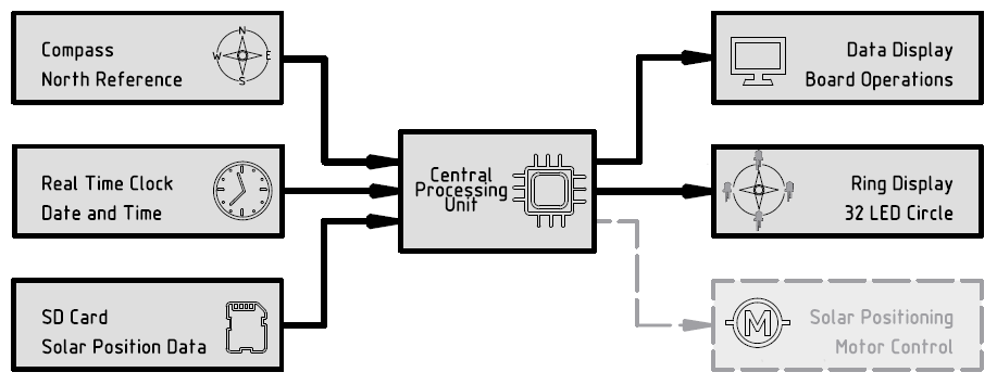
08/25/2019 at 13:33 • 0 commentsWith the revision 3 device up and running, planning continues for the next revisions. While revision 3 achieved single axis solar tracking, the goal for revision 4 has been set to achieve dual axis tracking and dual motor control. Revision 4 will be the last with the two-color LCD ring. Here, the ring will grow to 48 LED's, plus there are another 16 LED's for the newly added elevation tracking display line. With this setup, I reached the maximum of eight IO expanders on a single I2C bus. In fact, I am going to max out the Arduino MKR Zero down to the last of its IO pins. For revision 5, I plan to split the functions into a solar tracking master controller, and individual panel motor control boards. A bigger MCU in the master controller needs to be decided, wireless data transmission considered, etc.
Below is the design draft for the revision 4 controller board:
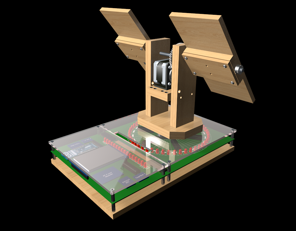
![]()
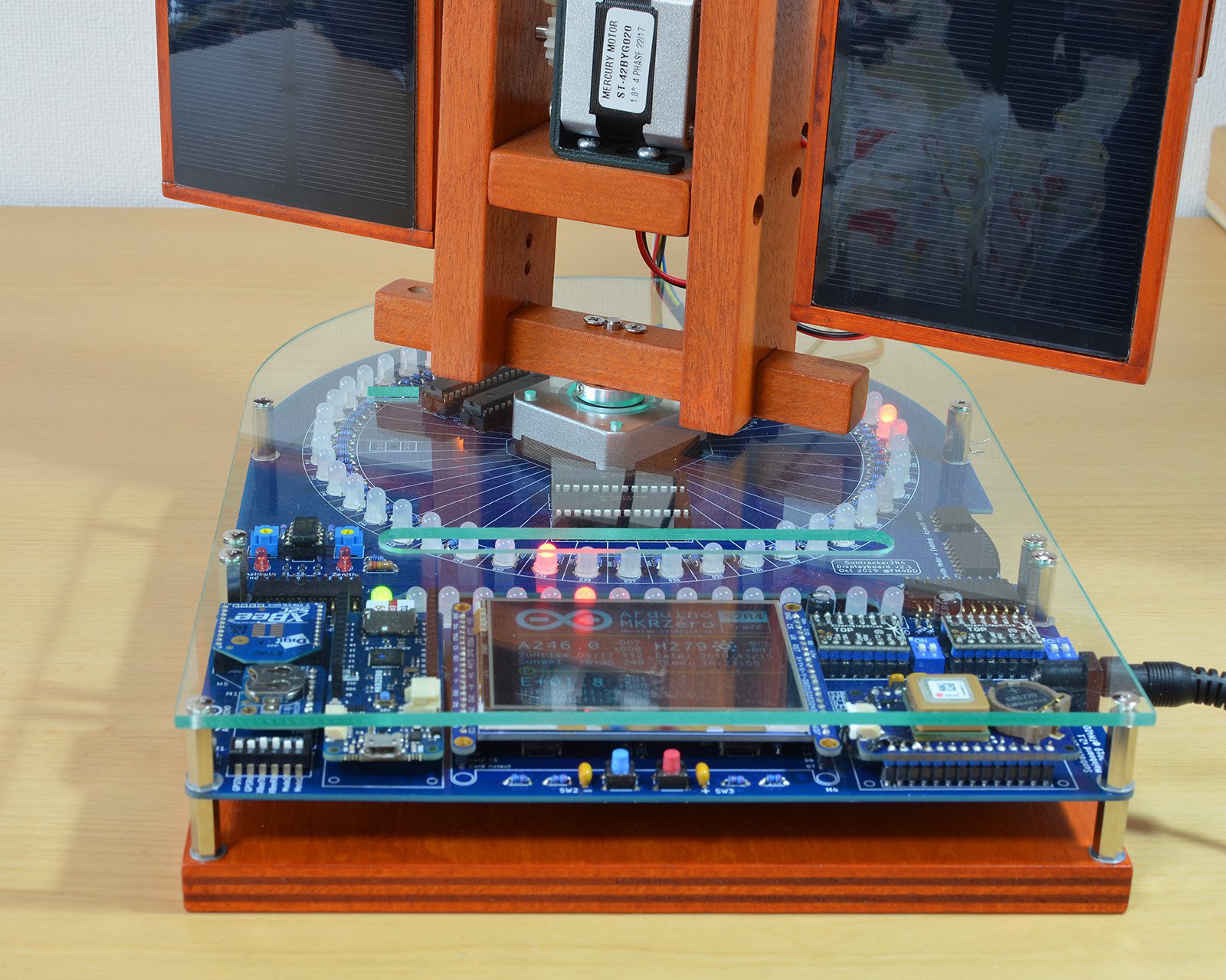
The controller will grow in size to approx. A4 (200x300mm), in order to host a small-scale 2x2W solar panel model on top of it. This model is to learn and become familiar with dual axis motor control. While it certainly won't achieve any real power generation, to practice small before scaling up is always a good idea. Also, in preparation of revision 5, I am implementing a TFT display for learning how to show the growing number of real-time parameters.
![]()
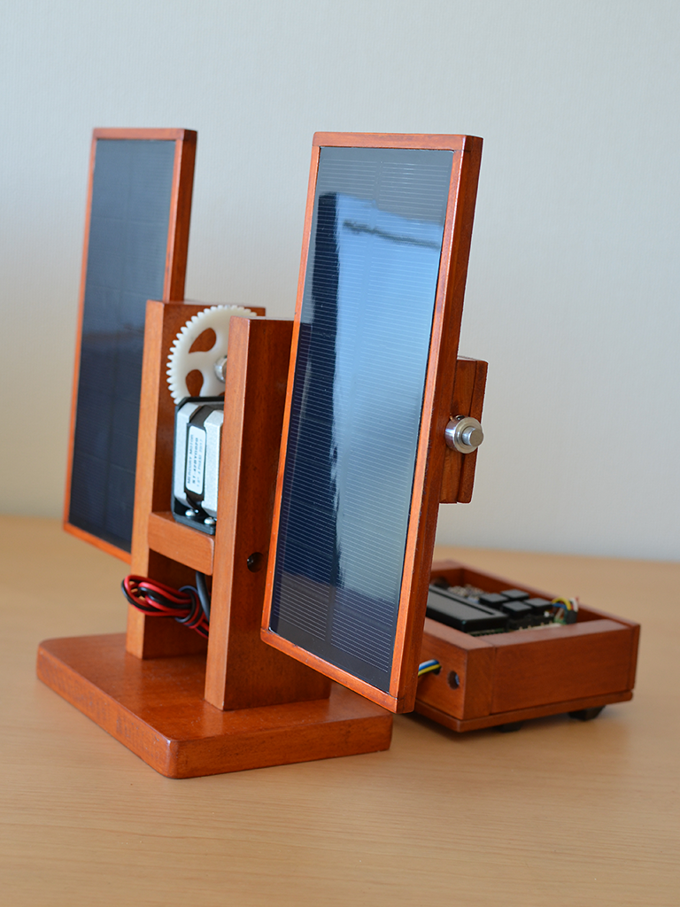
Below is a picture of the tiny 2x2W solar panel model, just imagine it to be 200W-class panels instead:
![]()
Now its back to KiCad, and the magic to turn a design into a real-world working device again. The schematic is almost complete, but routing and parts placement takes a lot of time.
P.S. I wonder if the small Arduino can manage this setup, only one way to find out...
-
Sun Tracker 2 Revision 3 - Adding a case
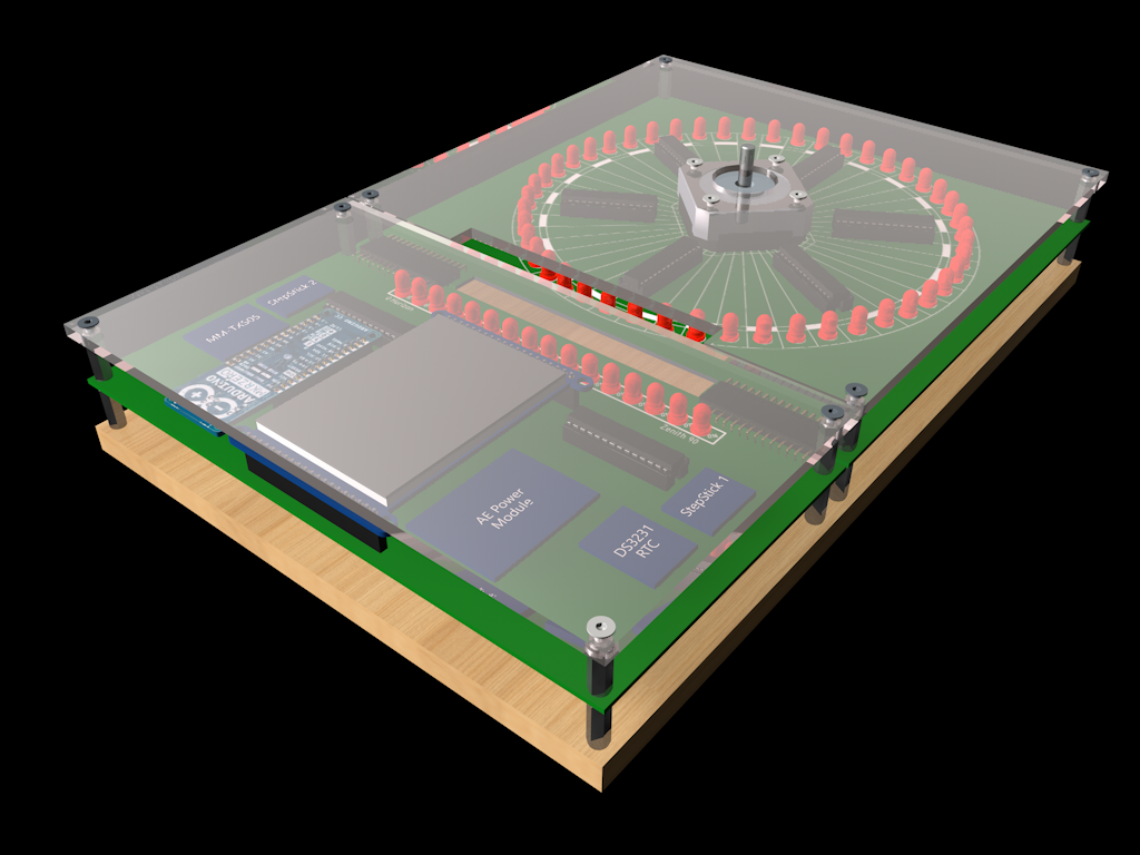
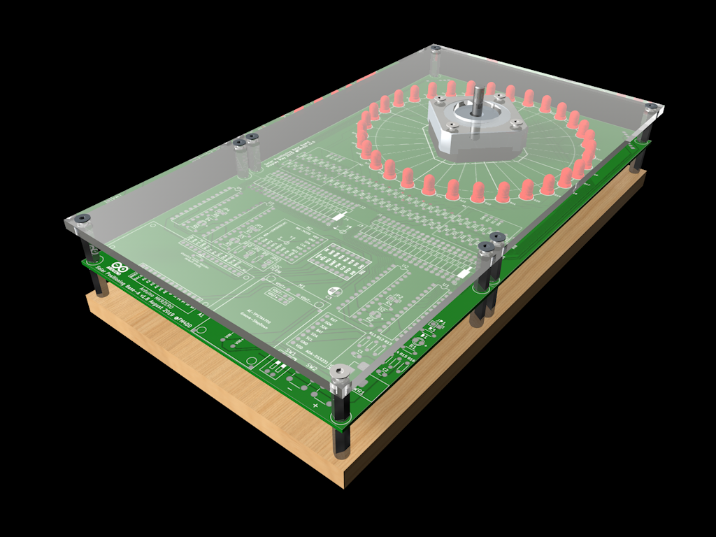
08/07/2019 at 12:59 • 0 commentsFor better daily handling, a simple "sandwhich"-style case has been drawn up. Below is the design study that has been converted to CAD drawings that were used for the final build. The CAD drawings are published in the GitHub repository cad folder. I am using 9mm plywood for the bottom, 4mm clear acrylic sheet for the top, and 15mm M3 spacers on either side of the board.
![]()
-
Sun Tracker 2 Revision 3 - Its coming together
08/07/2019 at 12:06 • 0 commentsWith Revision 3, the final shape starts to emerge. After becoming familiar with PCB production basics, it was time to turn the design into a device that can fully emulate and display the solar position.
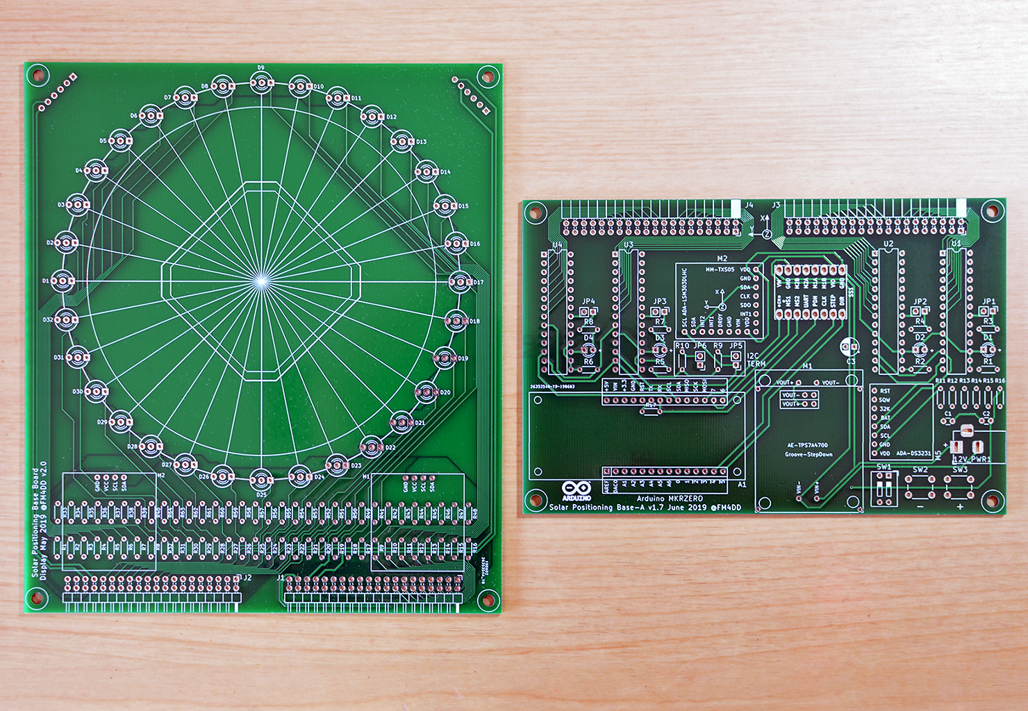
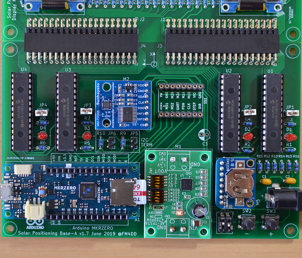
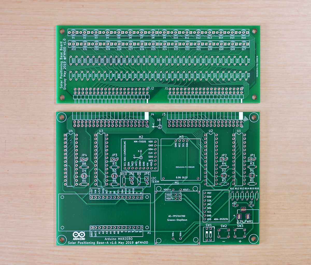
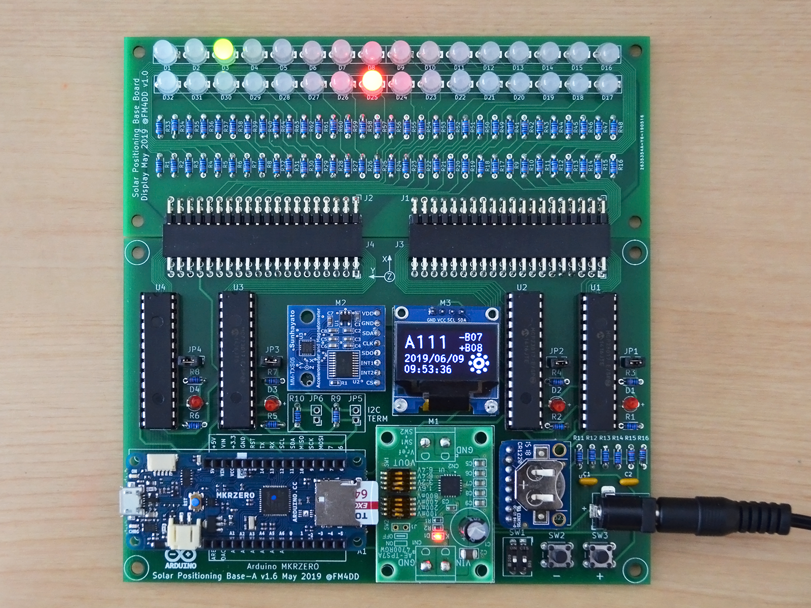
Expanding the displayboard to arrange the 32x LED set in a circle, and adding the stepper motor driver to the controller board meant moving the OLED display out to the display board. Adding the second OLED is not just for symmetry: showing the current azimuth angle in addition to the boards north heading adds to the convenience of quick data correlation. Here is the Revision 3 PCB set, consisting of mainboard v1.7 and matching displayboard v2.0. In the photo below, it shows the updated mainboard with the new stepstick connector fitted in the place of the previous OLED location. PCB design files (gerber), as well as the Arduino code are published in the revision 3 GitHub repository.
![]()
![]()
Adding the second OLED display to the I2C bus had an issue that required manually updating the u8g2 display library. I documented the solution in the GitHub issue tracker.
-
Sun Tracker 2 Revision 2 - Up & Running!
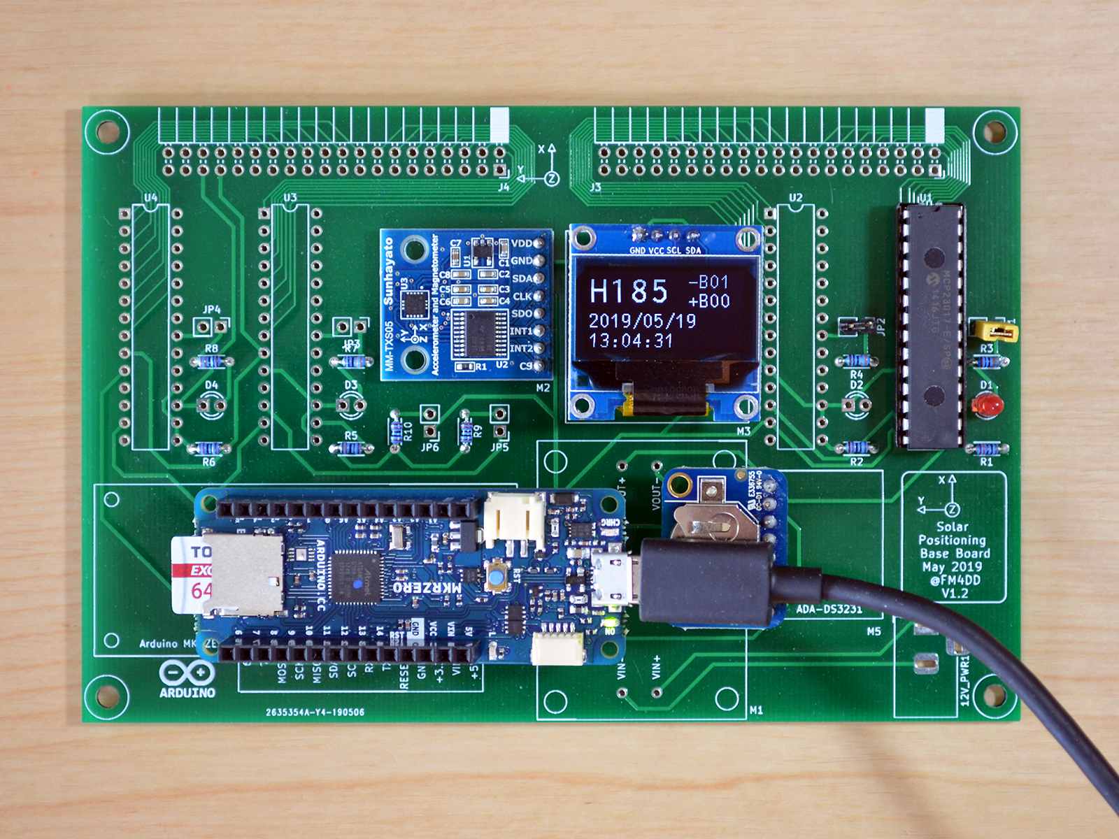
08/04/2019 at 07:51 • 0 commentsAfter the epic fail of mirrored Arduino footprint pins, I decided to double up and, together with the fixing the controller board, create the first version of the LED display board for the controller. To match the controllers size and use minimal space, a four-layer PCB became necessary. Because 4-layer boards require much more effort in construction and cost, I didn't go for the full LED ring design yet, but kept the first version with only two LED lines to gain experience.
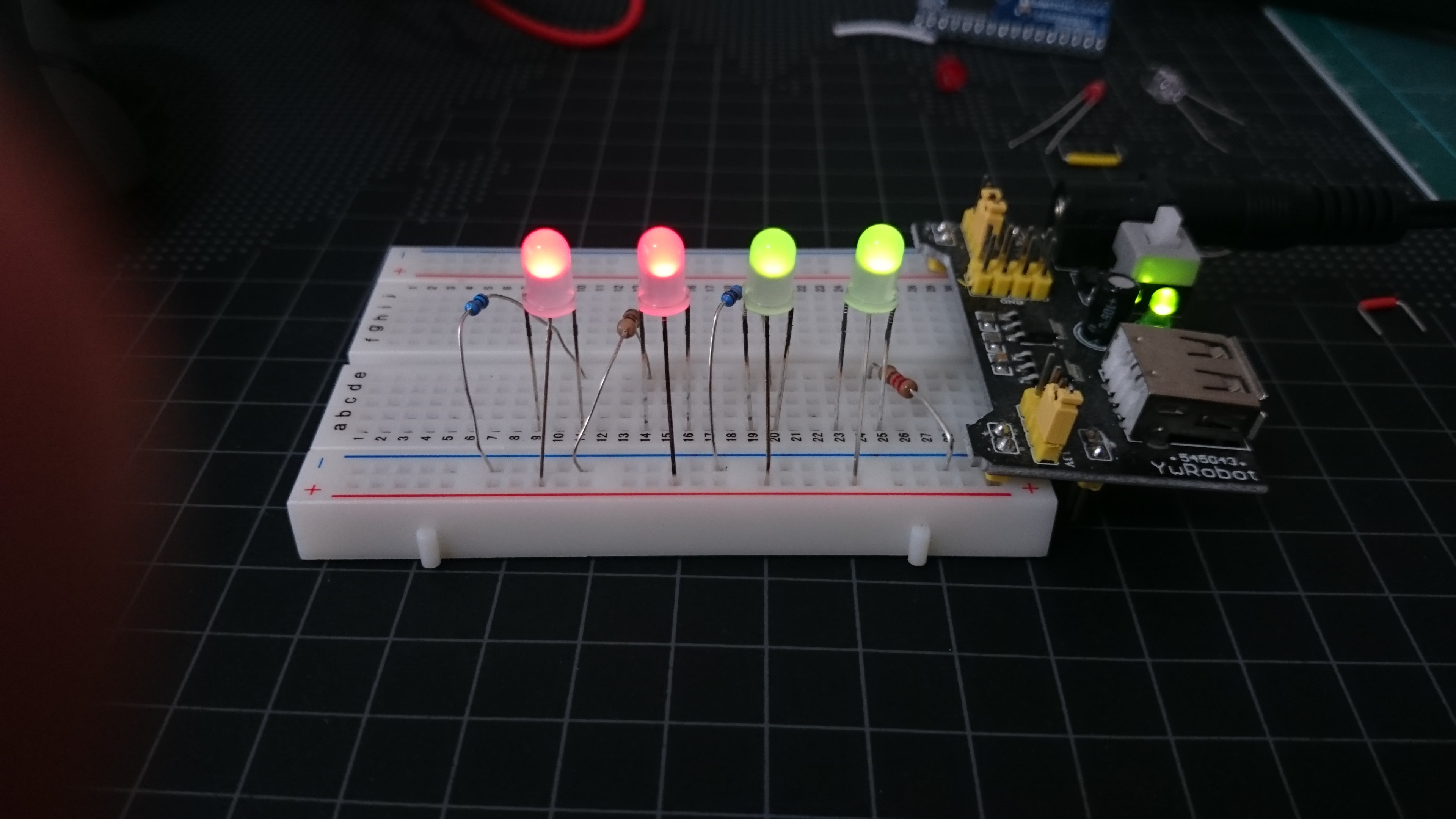
Now I was eager to see the board with the dual-color LED set in action. Dual-Color LED are basically two LED merged into one. Because of the difference in color/wavelength, colors may differ in their forwarding voltage. I run a few breadboard tests with different resistor values to get a approximate uniform brightness.
While updating the footprint, I also added a 2x DIP switch and two push button switches into the design. It is always handy to be able to control a few settings during the boards operation.
![]()
![]()
Revision 2 design and code is saved to the GitHub repository https://github.com/fm4dd/suntracker2-r2
-
Sun Tracker 2 Revision 2 - Setback with the PCB
08/03/2019 at 18:02 • 0 commentsAfter identifying the need for a bigger controller, I picked the Arduino MKR Zero. The Zero has a sufficiently small footprint, generous 32K RAM, 256K Flash, and comes with a build-in MicroSD card reader. The 32bit architecture will be helpful for working with bigger data types, and the 48Mhz are much speedier, too.
![]()
The choice of the Arduino controller determined the new system voltage to 3.3 volts. Time for PCB design, adding all components except for the stepper motor control. The board had no space left, so I decided to leave that for later.
For creating the controller board PCB design I used KiCAD 5. After two misguided attempts, the third version looked ready for production. Instead I was in for some disappointment...
![]()
![]()
As it happens, I fell for the #1 error in PCB design: having created a mirrored footprint for the Arduino MKR Zero. How embarrassing! After finding the presentation for the top-5 footprint mistakes, it was a bit of consolation to learn that even pro's tend to make this mistake. Nevertheless I partly populated the board, using sockets to preserve modules, and turning the Arduino around to align the pins on an awkward angle. I wanted to see if the board otherwise works, and voila, the board works great, flipped Arduino pins put aside.
-
Sun Tracker 2 Revision 1 - Prototyping Board
08/03/2019 at 17:14 • 0 commentsWith the compass functionality tested on a breadboard, the next step is to transfer it to a universal prototyping board, adding a status display and IO expansion ports to drive a LED ring that simulates the horizon. For the board, I am going to use the Takachi TNF 89-136.
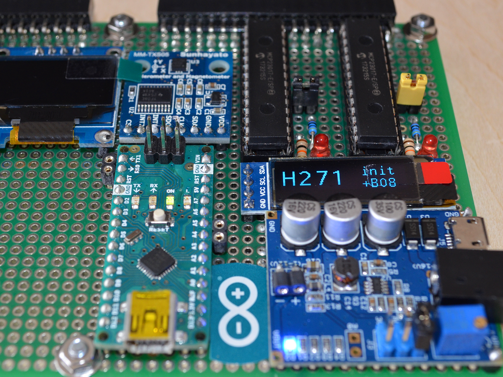
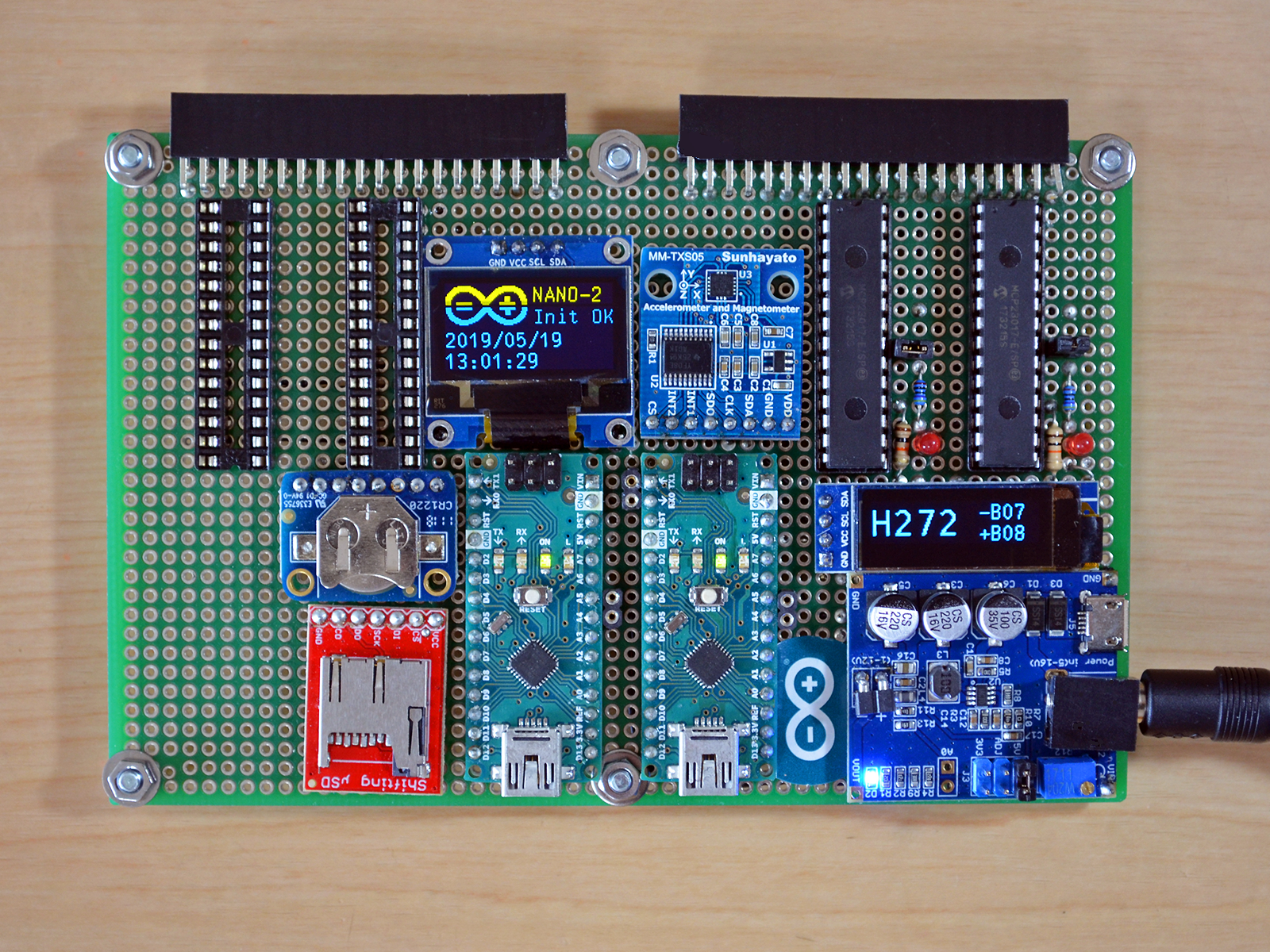
![]() I had an Ardunio Nano at hand to be used as the micro controller, which will later turn out to be vastly inadequate to drive all the peripherals. At this stage, The Nano was holding up OK: driving the LSM303 magnetometer sensor, the 128x32 OLED display, and two MCP23017 IO expanders from Microchip, all over the I2C bus. In front is the stepdown voltage regulator from Seeed Studio.
I had an Ardunio Nano at hand to be used as the micro controller, which will later turn out to be vastly inadequate to drive all the peripherals. At this stage, The Nano was holding up OK: driving the LSM303 magnetometer sensor, the 128x32 OLED display, and two MCP23017 IO expanders from Microchip, all over the I2C bus. In front is the stepdown voltage regulator from Seeed Studio.![]()
![]()
In the left half of the universal prototyping board, I placed the remaining components: the DS3231 RTC clock, the MicroSD card reader, and a bigger 128x64 OLED display. For data exchange, was going to connect the two Nano over the serial line interface. But before that, I run into severe RAM space issues. The MicroSD card driver requires >512 Bytes buffer space, the bigger 128x64 OLED reserves a larger frame buffer, exhausting the 2K RAM space of the Nano without having written any code yet.![]() A second challenge was my patience and steady hand. To route and wire 96+ connections required for the LED ring manually, it was going too slow and error-prone. I decided to better get a bigger CPU, and I'd better create a PCB.
A second challenge was my patience and steady hand. To route and wire 96+ connections required for the LED ring manually, it was going too slow and error-prone. I decided to better get a bigger CPU, and I'd better create a PCB. -
Starting to build a sun tracker - or how to find North
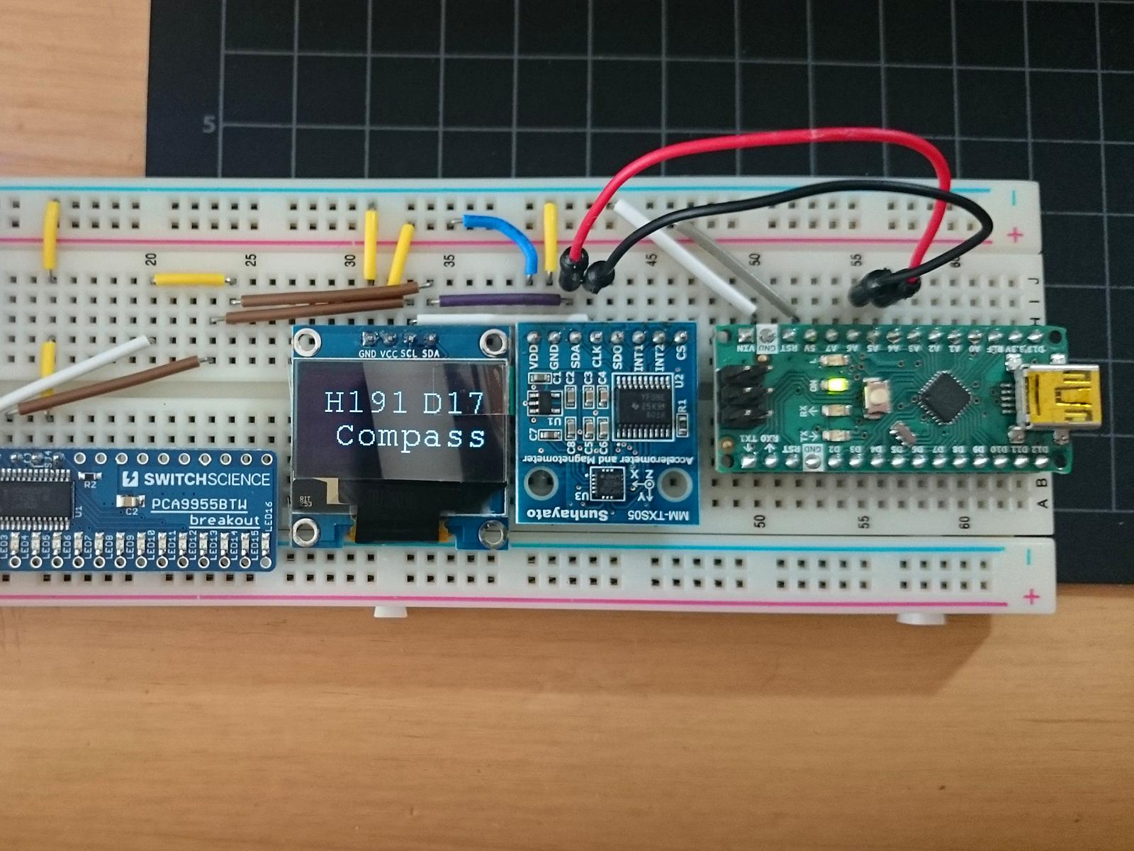
08/03/2019 at 03:23 • 0 commentsThe first steps on the solar tracking project were taken in April, when I was reading about building a digital compass. There are various project descriptions on the net, and I was interested what sensor is best suited for that task. Based on what I can source locally, I zeroed in on modules with the LSM303 chip, made by ST Microelectronics. Below shows the first breadboarding tests with the MM-TXS505 module from Sunhayato.
![]()
The MMTXS505 modules uses the LSM303D chip released in 2012. It is quite stable, and offers the ability to select one of two possible I2C addresses. I noticed that later chip revisions (e.g. LSM303DLHC) only hardcode one address, which prevents using more than one sensor on a single I2C bus. Now that I can determine North, I can plan for adding the modules that would add the sun position information and provide the tracking output.
SunTracker 2 Revision 3
A learning platform for optimizing solar systems energy output through alignment to our suns path across the sky.
 Frank
Frank