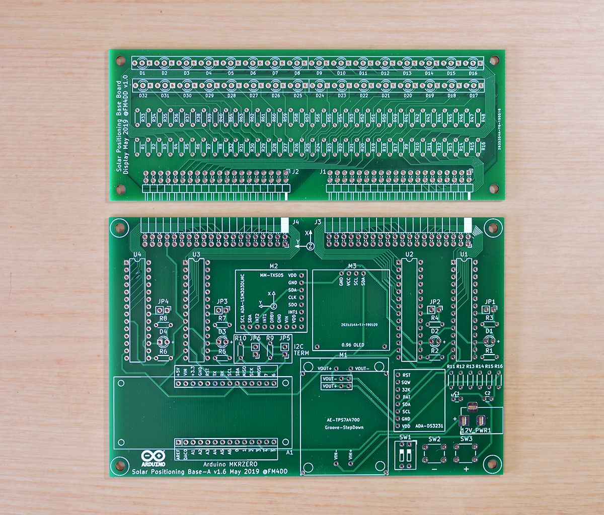
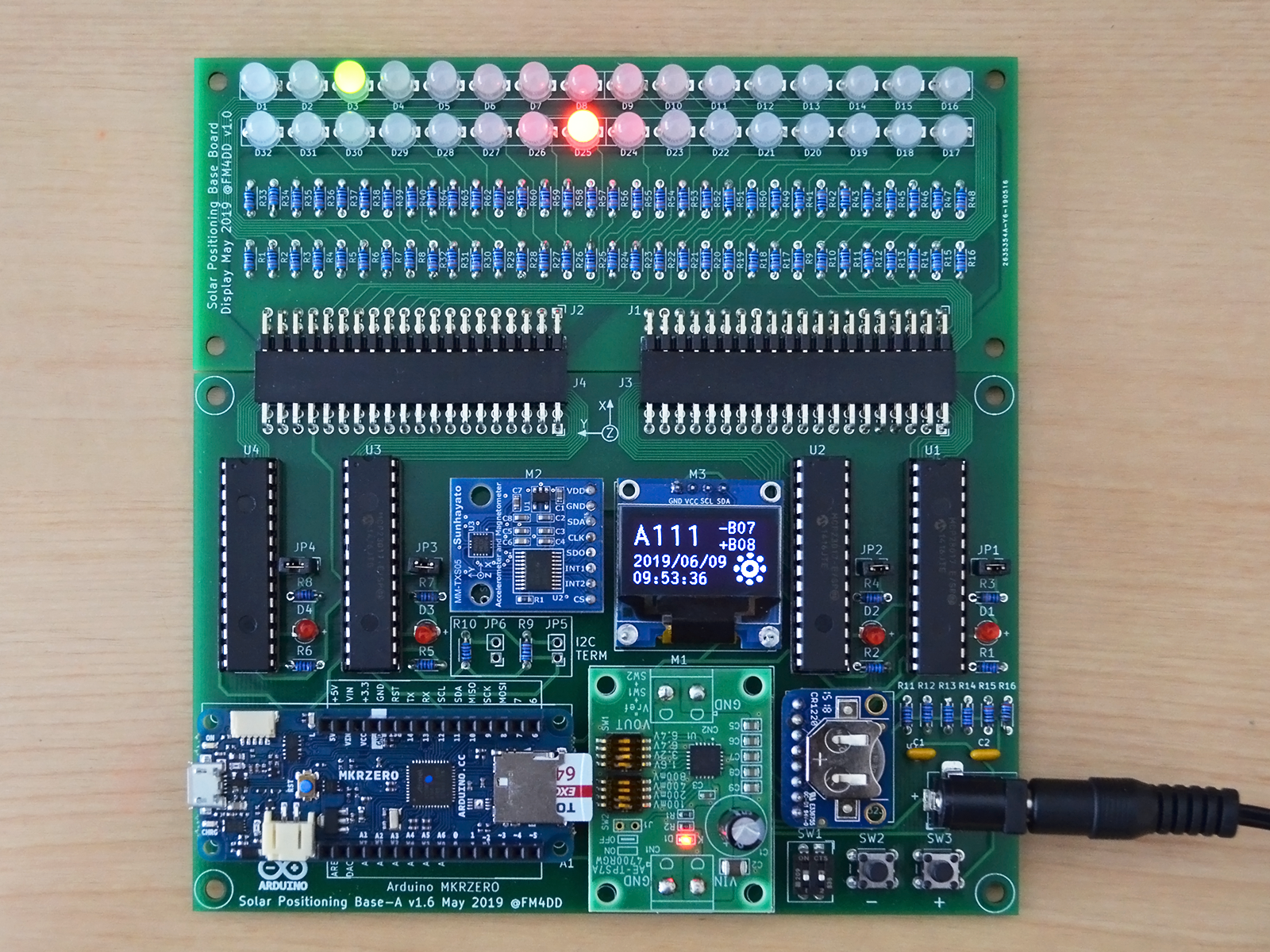
After the epic fail of mirrored Arduino footprint pins, I decided to double up and, together with the fixing the controller board, create the first version of the LED display board for the controller. To match the controllers size and use minimal space, a four-layer PCB became necessary. Because 4-layer boards require much more effort in construction and cost, I didn't go for the full LED ring design yet, but kept the first version with only two LED lines to gain experience.
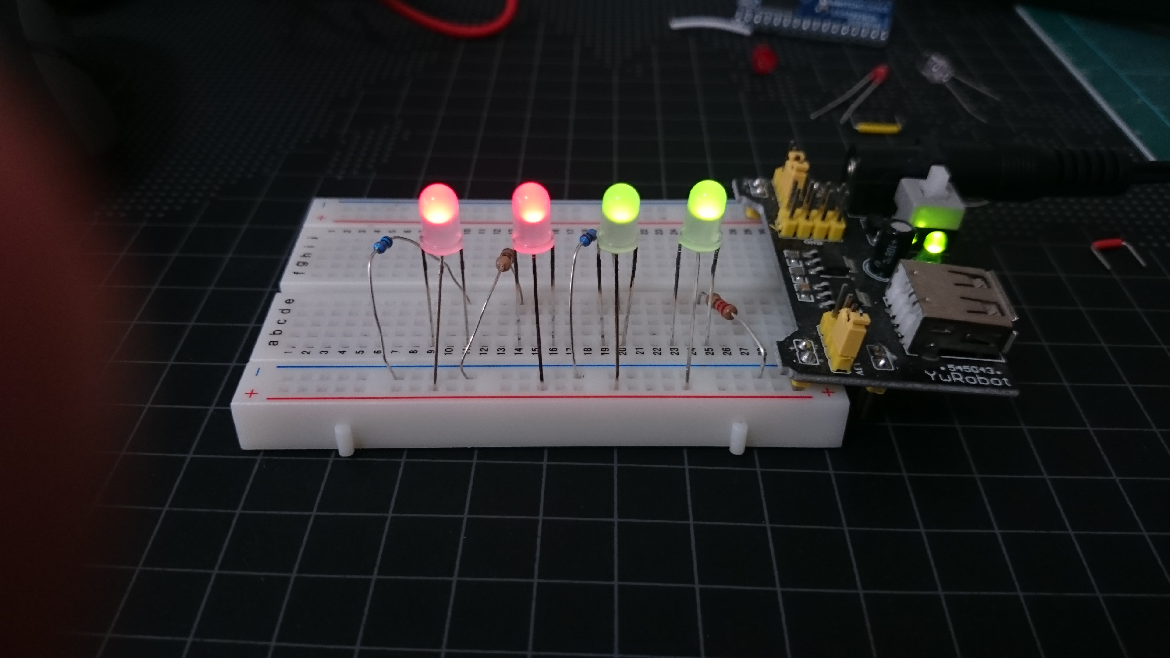
Now I was eager to see the board with the dual-color LED set in action. Dual-Color LED are basically two LED merged into one. Because of the difference in color/wavelength, colors may differ in their forwarding voltage. I run a few breadboard tests with different resistor values to get a approximate uniform brightness.

While updating the footprint, I also added a 2x DIP switch and two push button switches into the design. It is always handy to be able to control a few settings during the boards operation.


Revision 2 design and code is saved to the GitHub repository https://github.com/fm4dd/suntracker2-r2
 Frank
Frank
Discussions
Become a Hackaday.io Member
Create an account to leave a comment. Already have an account? Log In.