 Yann Guidon / YGDES
As with other projects, I use Hackaday to "open source" my work, keep design notes tidy, help and inspire others... Here, I don't believe the system can be covered by copyright so I guess that no license applies.
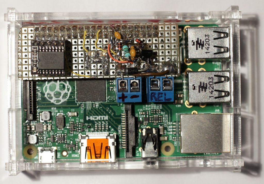
The system:
A Raspberry Pi controls some lights and stuff. This could be any other programmable digital platform though.
The problem:
a safety relay must be released when the main program stops.
atexit() is not fired in all the cases and can't garantee perfect reliability and safety.
The approach:
An "active" system is required: it is not enough to set a GPIO pin off at the end of the program. There is no OS feature that restores the GPIO state in ALL conditions (such as emergency shutdown or i the kernel hanged).
Usually, people use a "watchdog", a piece of HW that is polled continuously and that resets the system when a timeout occurs.
In the current system, there is no need to reset the computer, only the safety relay.
A GPIO pin is already used: setting it works but clearing it is not perfect, for countless platform-specific reasons.
The idea:
Borrow from the classical watchdog paradigm with software polling.
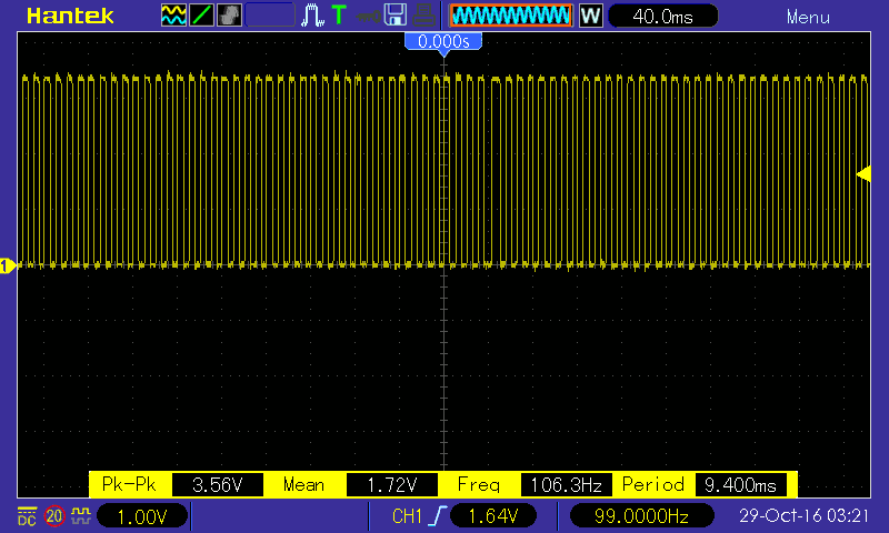
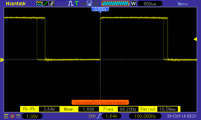
Instead of pinging a particular memory or I/O address, the program toggles the existing GPIO pins instead of using a given signal level.
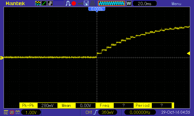
The program can generate at least 10Hz from the main loop.
The design:
Now the question is how to turn the oscillation into a level.
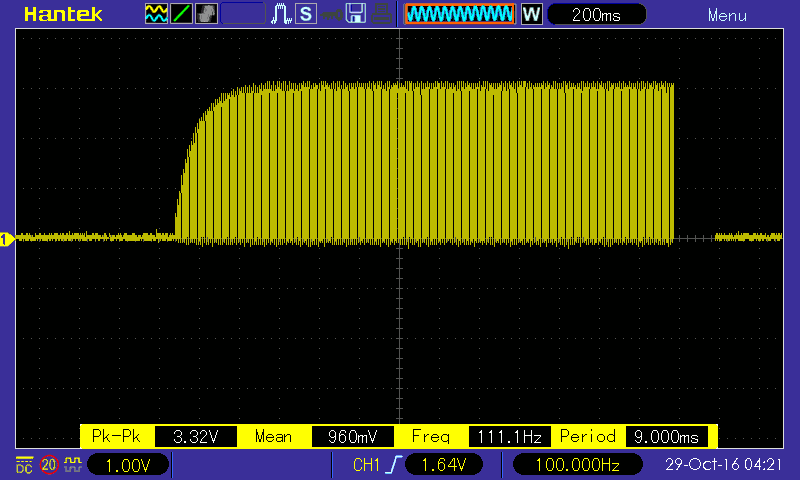
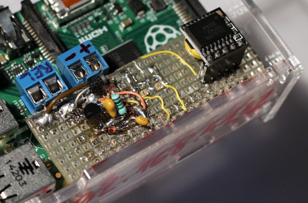
DC signals shouldn't pass, only AC and transients : a blocking cap (C1) is required.
A charge pump follows, with a couple of diodes (Schottky for lower drop).
At the end of the chain, the charge pumps fills a storage cap (C2) that controls the gate of a N-MOSFET.
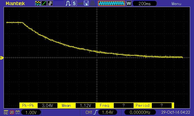
In the middle, a diode (SD1) rectifies the current and lets it only charge the storage capacitor (think about a primitive crystal radio). Discharge goes through a high-value resistor (R1, 1M) to provide a long (and adjustable ?) RC time constant.
SD2 lets the blocking cap C1 recharge.
Did you notice the absence of freewheel diode across the relay's coil pins ? It is not needed because the MOSFET does not switch abruptly and the coil has a lot of time to release its energy.
If higher current is required, the charge pump can be extended to two stage to (almost) double the initial voltage. Since the Pi drives its pin with 3.3V, the single-stage circuit provides about 3V to the MOSFET's gate, which is enough for a small relay.
The parts values are chosen for a time constant of approximately one second. C1 could be increased to require fewer cycles until the MOSFET is fully conducting, though it also depends on the input signal's frequency.
Logs:
1. First implementation
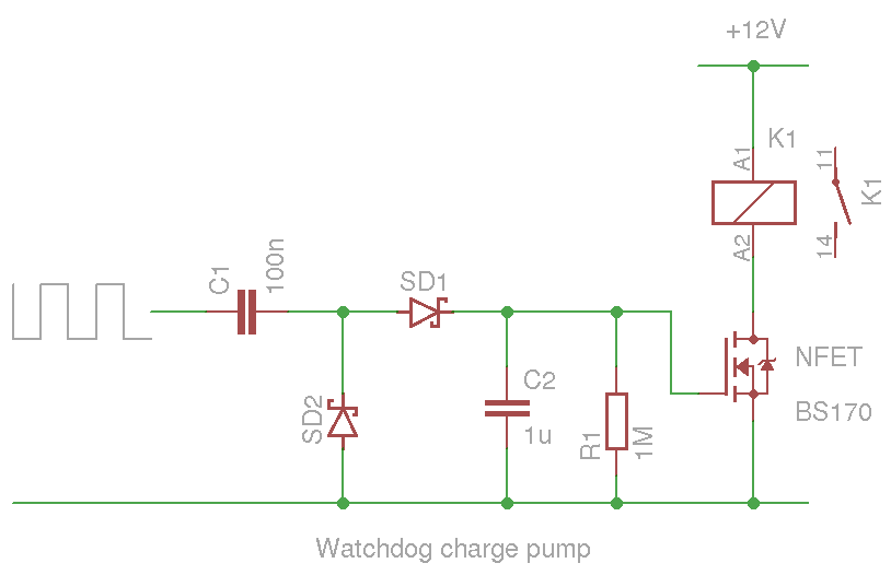


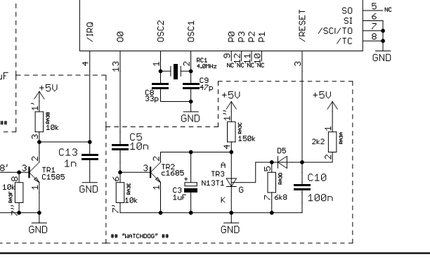


Here is the schematic of the watchdog from YPVS controller: https://goo.gl/photos/KidSUAodBNy9LcAu7