 Andrey V
Small video about MODBUS MCU features.
- 0:00 Connections
- 1:00 Work with INPUT module
- 3:00 Configuration for OUTPUT module
- 4:00 Initial condition configuration and test
- 4.45 WATCHDOG for modbus slave configuration and test
What functionality I need from this controller?
- Reliability!!! All Modbus slaves are connected to each other via RS485 line. If something bad happens with one device (220V on transducer for example) all other devices will die.
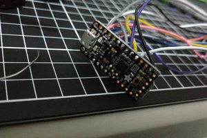
- My controller must be able to work with input modules(DI8, DIO4) and output modules (DO8, DIO4, RLY4, SSR4) without reprogramming MCU.
- Controller must be equipped the standard 20 pin interface for modules.
- It will be good to have some radio interface on board.
- Radio interface configuration must be easy (w/o any additional soldering).
- The radio link is not so stable and depends on many factors, so I need some protection if the connection will be lost
- Initial condition. It will be good to have the ability to save initial outputs condition and restore it on each power on.
- Device must be as small as possible (max size 1U DIN RAIL).
I will explain the schematics etc later. Stay tuned)
 Psyrax
 malo
malo
 PointyOintment