-
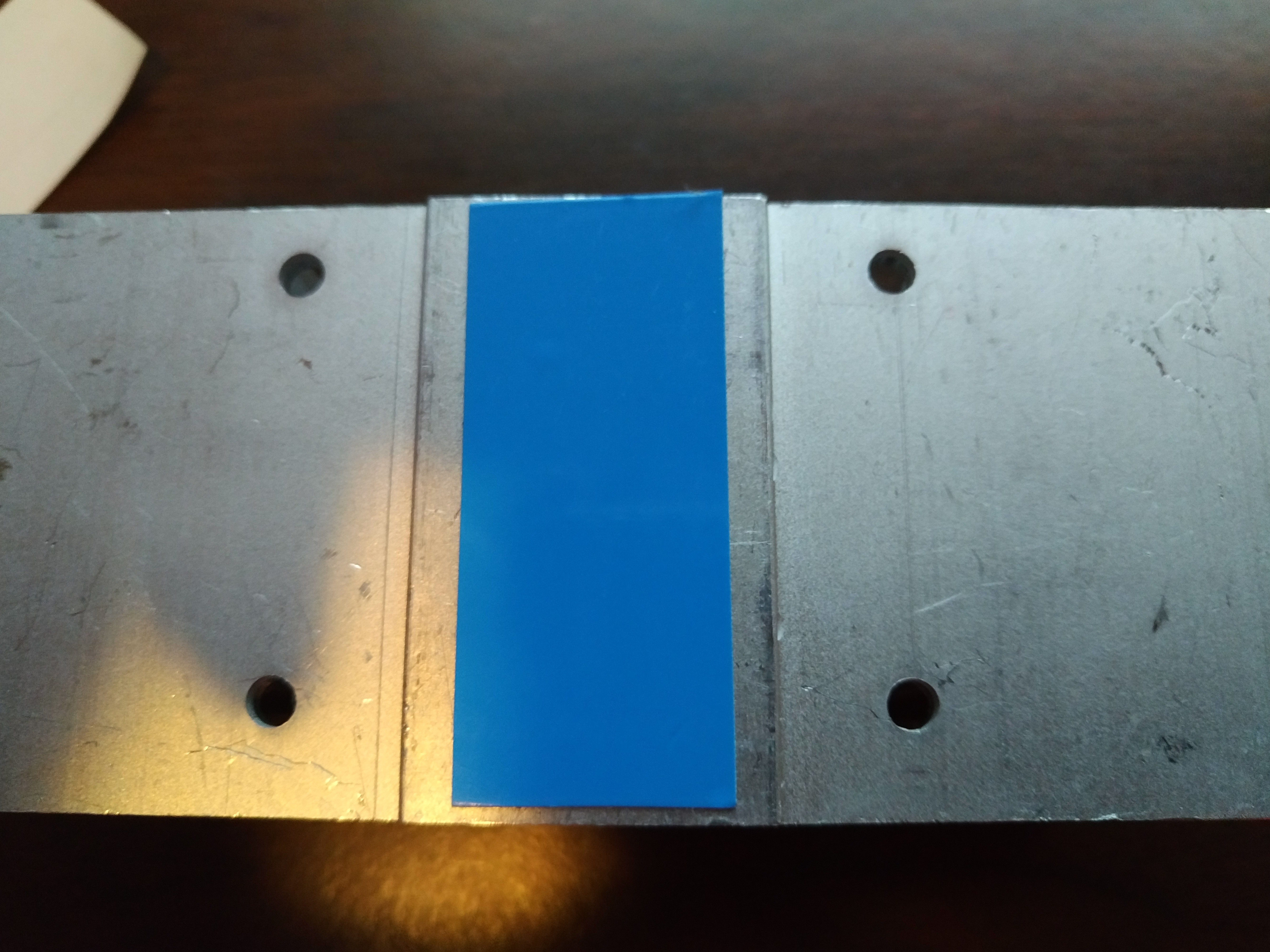
1Attach Thermal Adhesive to Heat/Coldsink
![]()
-
2Attach Peltier to Heatsink via Thermal Adhesive
Remove the blue protective plastic from the thermal adhesive. Place the Peltier module on the thermal tape numbers down
![]()
-
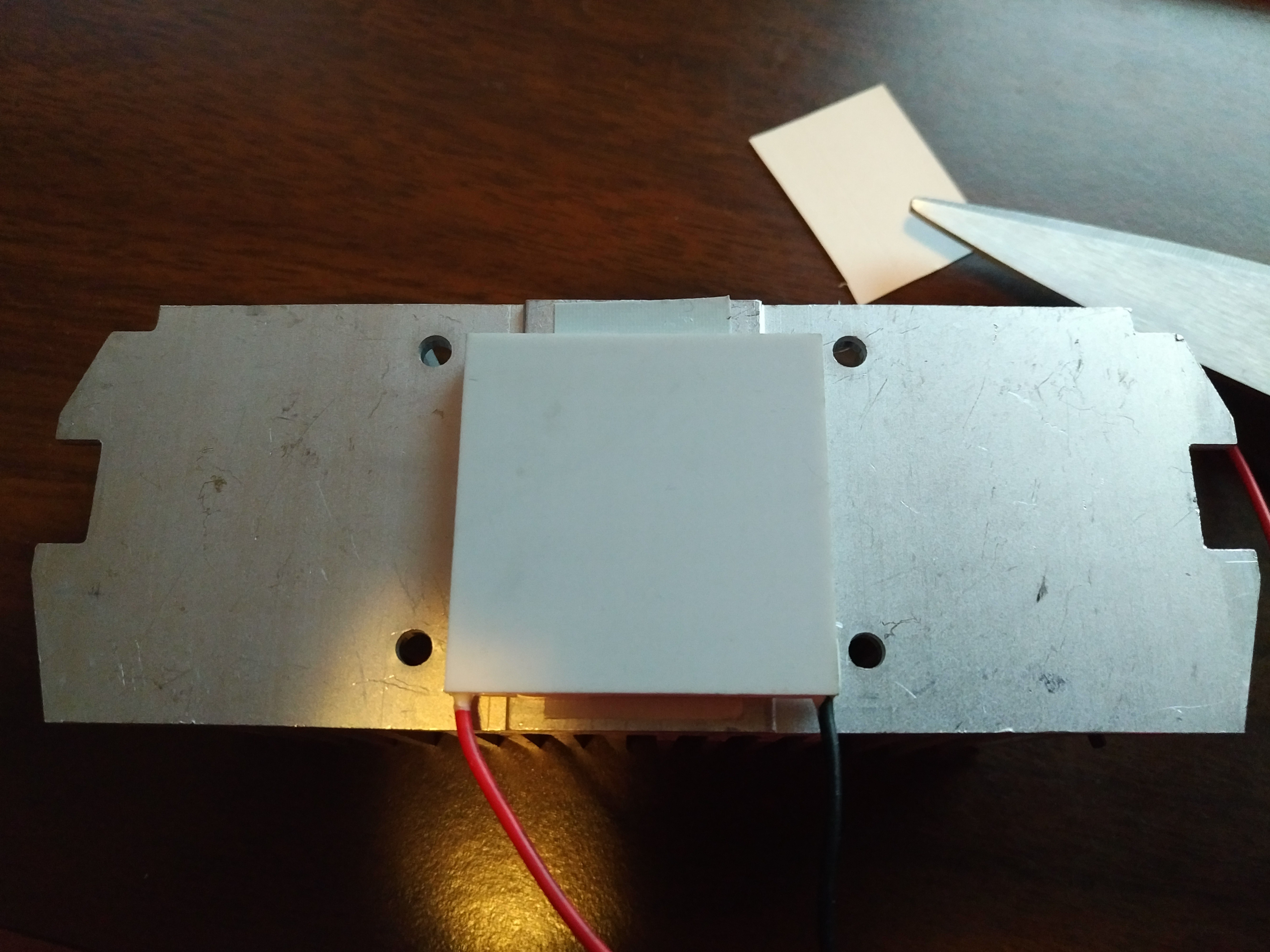
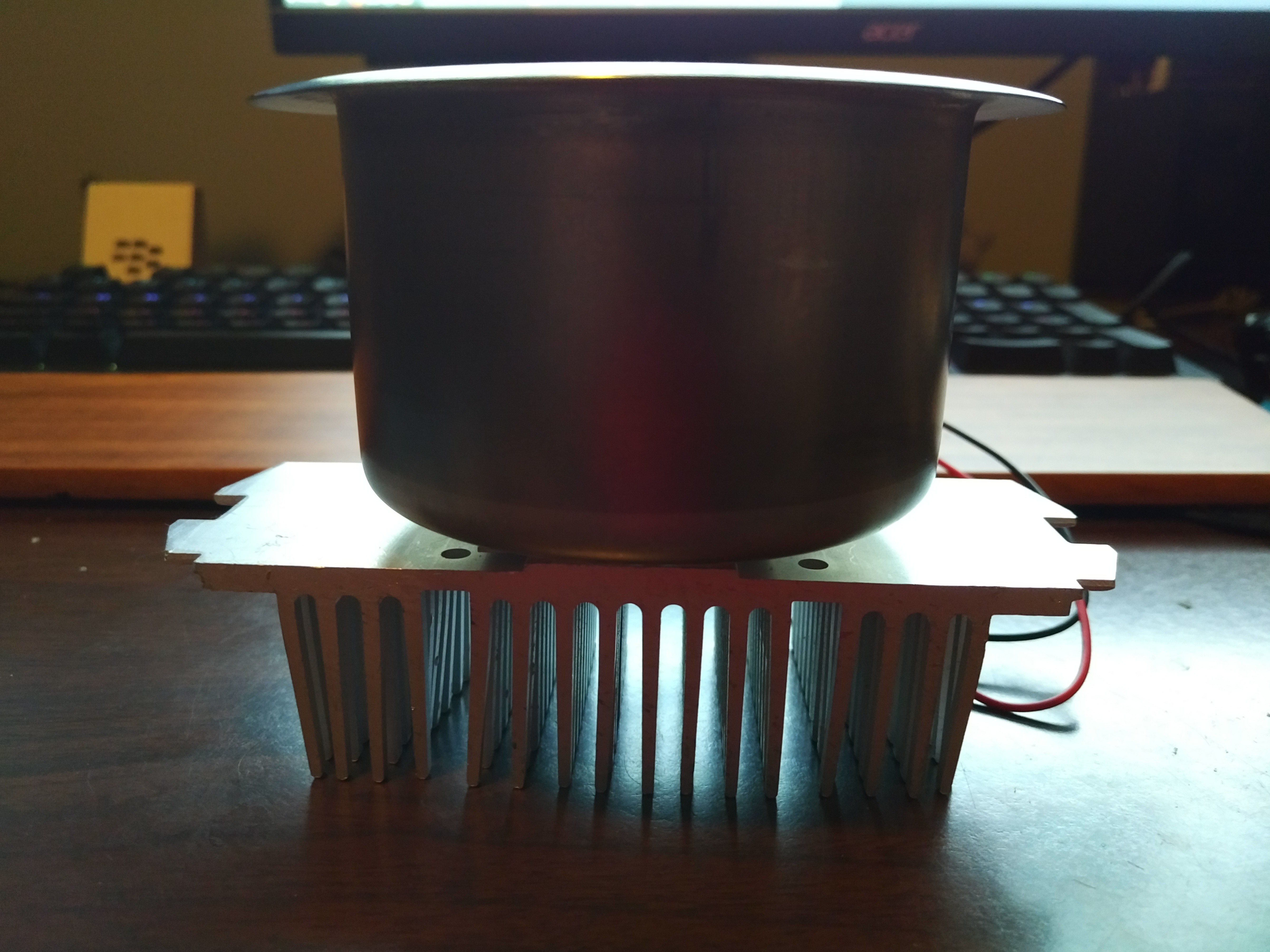
3Attach Thermal Adhesive to Peltier and Attach Cup Holder
![]()
Apply 2 pieces of adhesive tape to the Peltier heater/cooler, remove the blue plastic from the adhesive and attach the cup holder. Make sure you get it centered the first time as the adhesive is very strong and the Peltier units are fairly fragile!
-
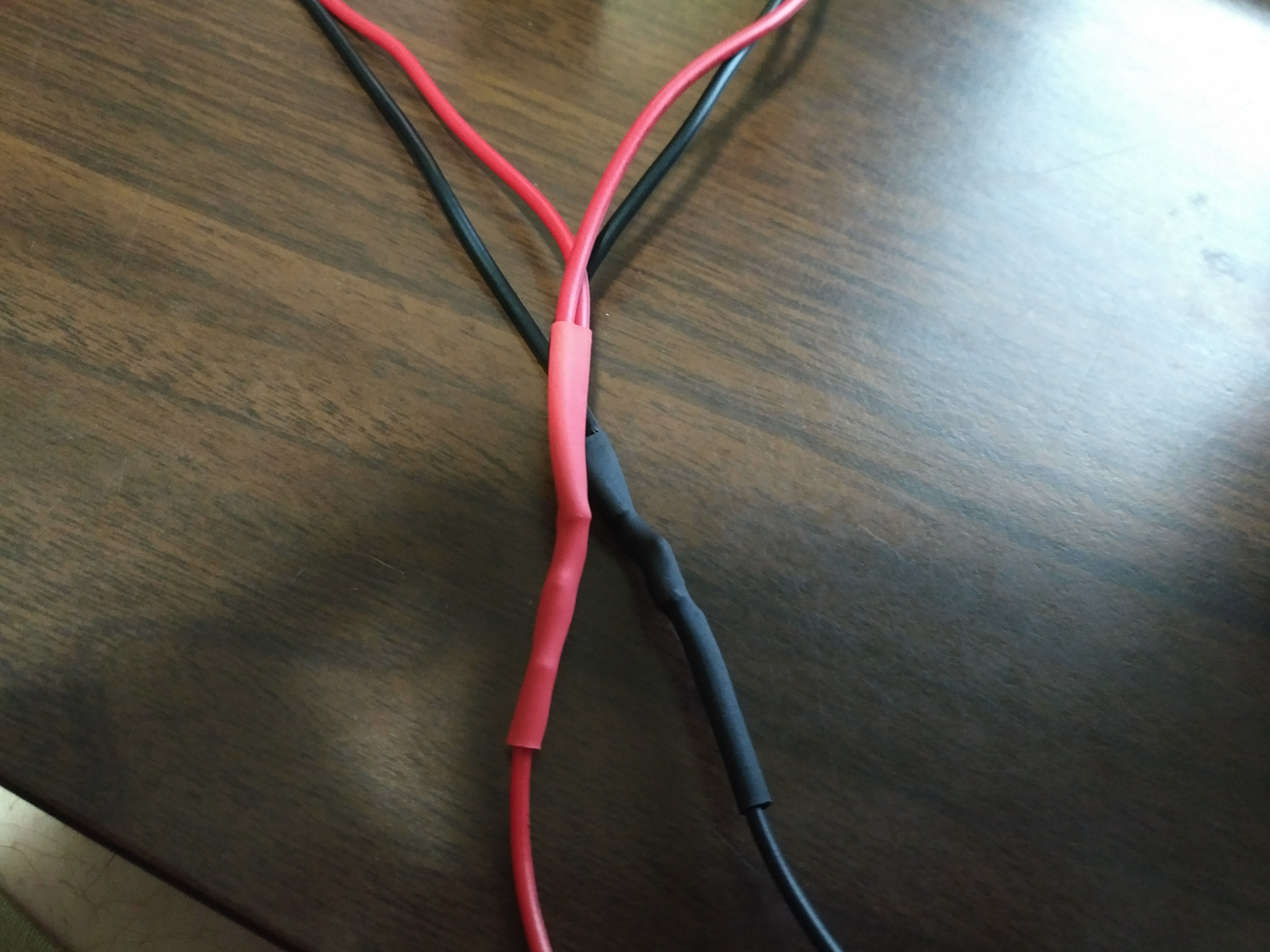
4Solder 2 Wires on Both Red and Black Wires of Peltier
![]()
Split the red and black wires into 2. Don't forget the shrink wrap
-
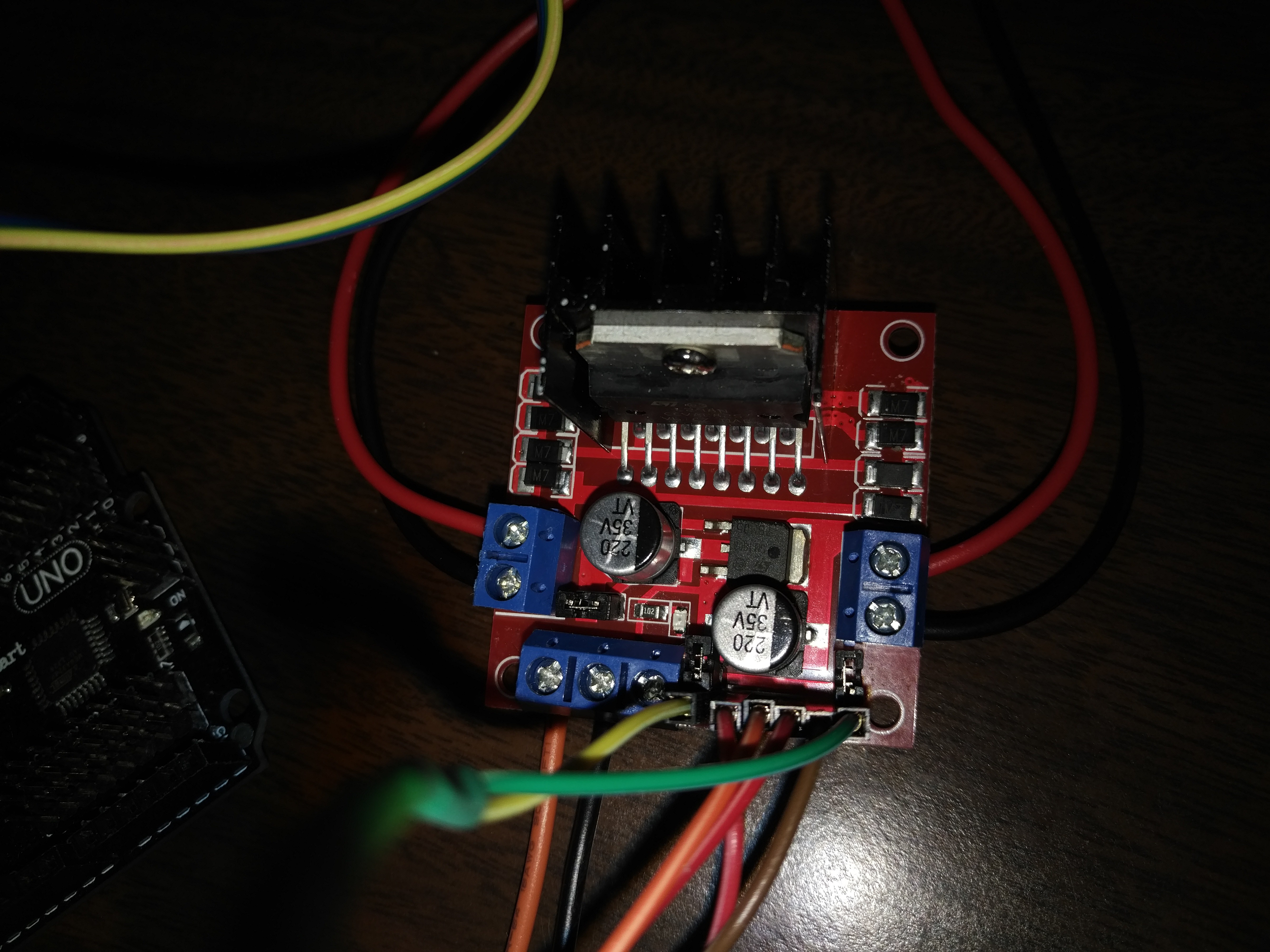
5Attach Peltier Wires to H-Bridge
![]()
Attach both black and both red wires to the H-Bridge as shown. The reason for splitting the wires is to take advantage of both sides of the dual H-Bridge for maximum current. The Peltier can pull ~4A at its peak.
-
6Connect the +12V Supply Power and Ground Wires to The H-Bridge
See the Orange and Black Wires in blue terminal block in the photo above and Schematic
-
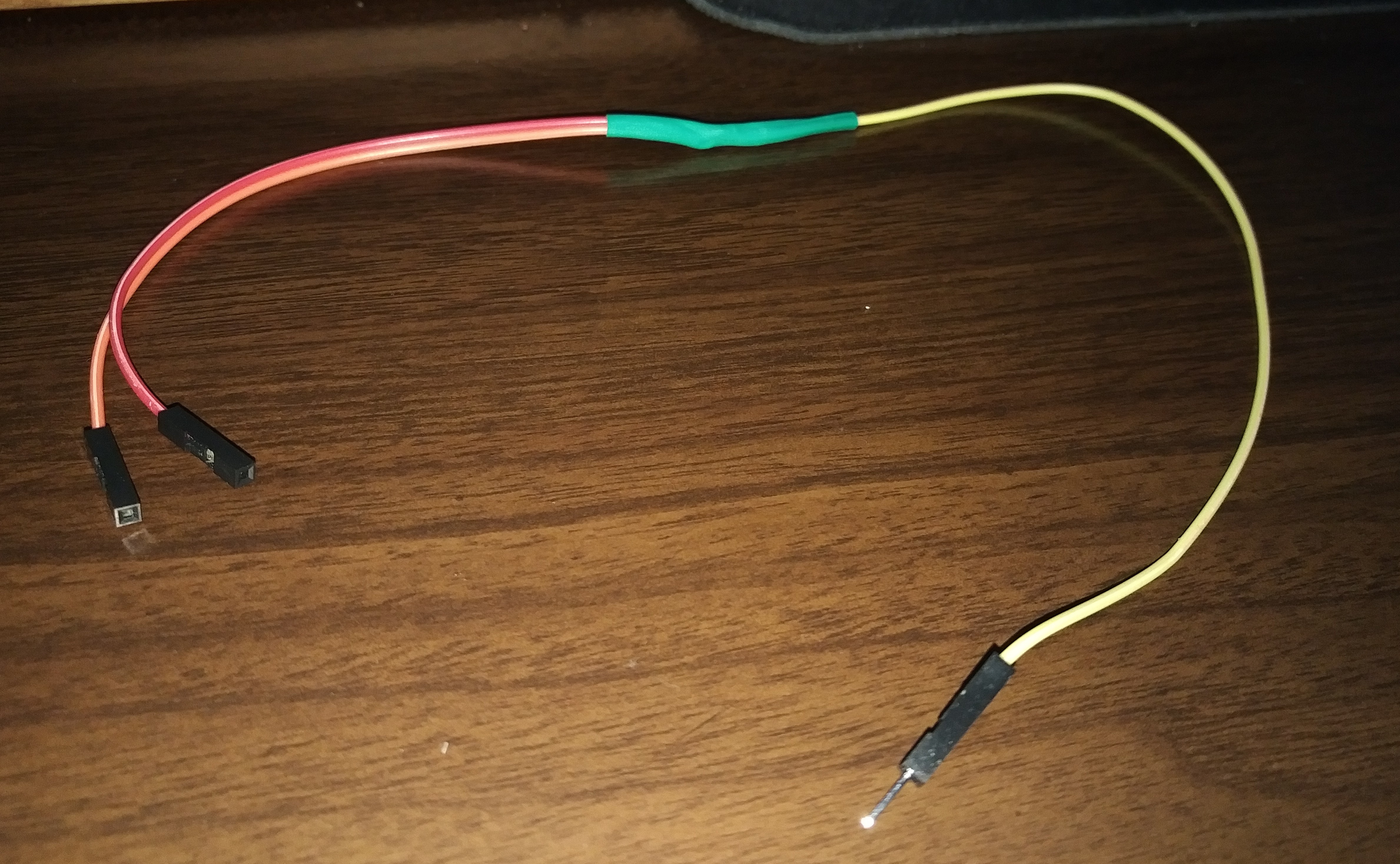
7Create 3 Single Male to Dual Female
![]() Cut solder and shrink wrap 3x Single Male to Dual Female jumper wires like shown in picture
Cut solder and shrink wrap 3x Single Male to Dual Female jumper wires like shown in picture -
8Connect the Wires Created in Previous Step to the H-Bridge and Arduino
Arduino UNO H-Bridge Pin 9 ENA, ENB Pin 10 IN2, IN3 PIN 11 IN1, IN4 -
9Place the MLX90614 into 3D Printed Enclosure and Attach Wires to Sensor and Arduino
Arduino Uno MLX90614 SCL SCL SDA SDA GND GND 5V VCC ![]()
-
10Connect the Arduino to the Computer via USB
Use the USB A to B cable to connect the Arduino to a host PC running the Arduino IDE (Version 1.8.9 recommended )
Room Temperature Cup Holder
Cup Holder to Keep Your Beer (or Other Beverage) at Room Temperature
 Cut solder and shrink wrap 3x Single Male to Dual Female jumper wires like shown in picture
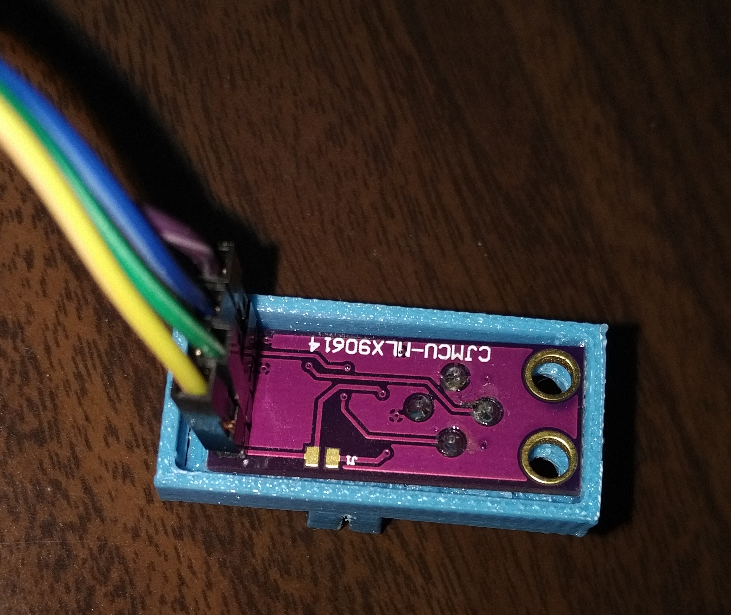
Discussions
Become a Hackaday.io Member
Create an account to leave a comment. Already have an account? Log In.