Background
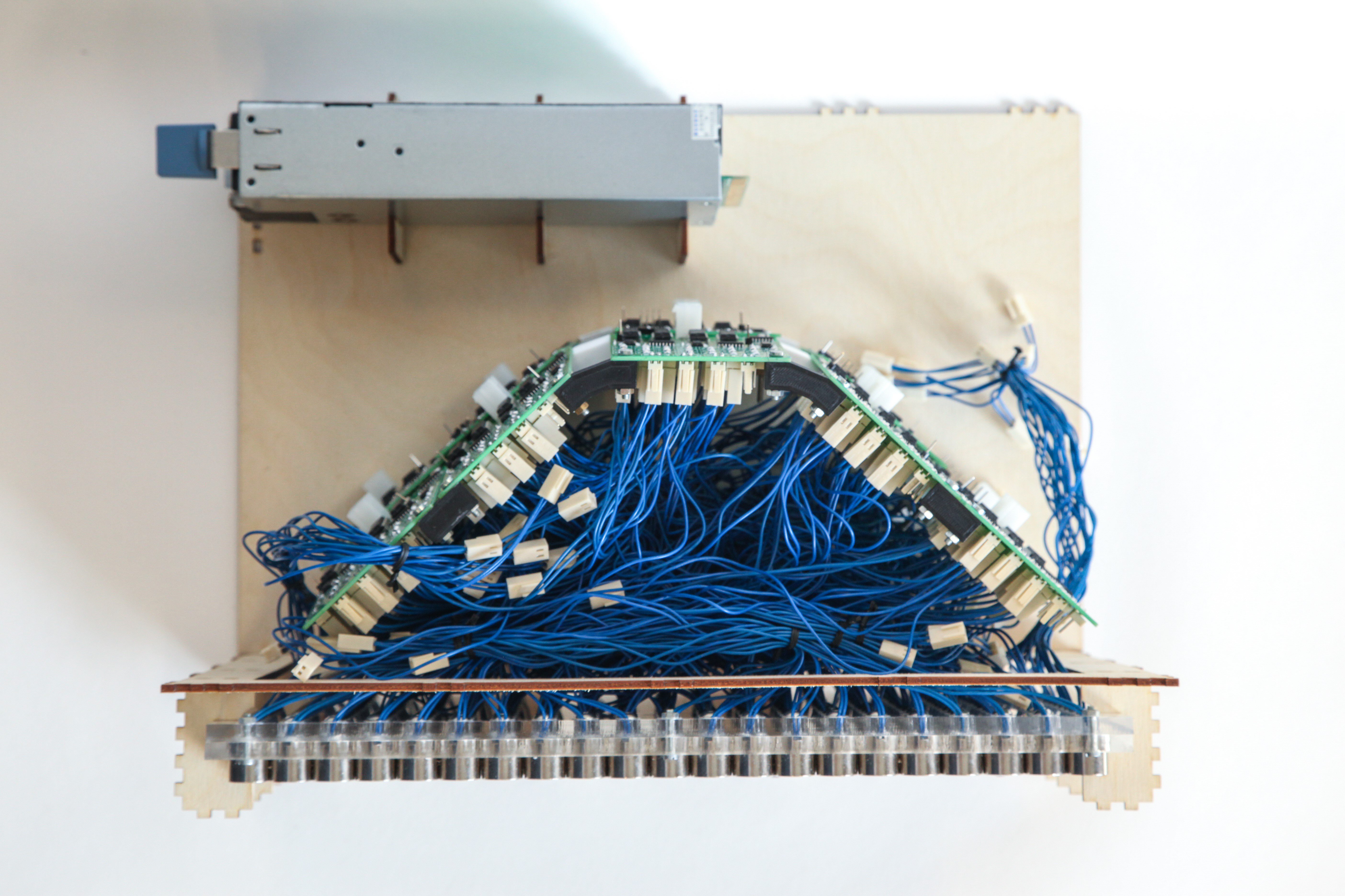
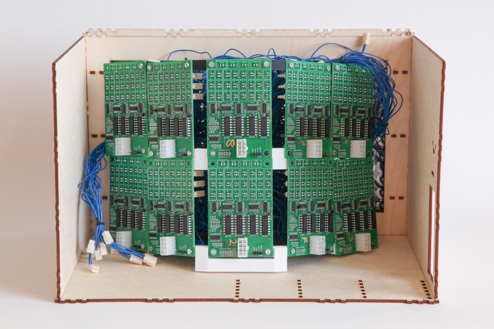
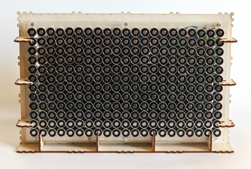
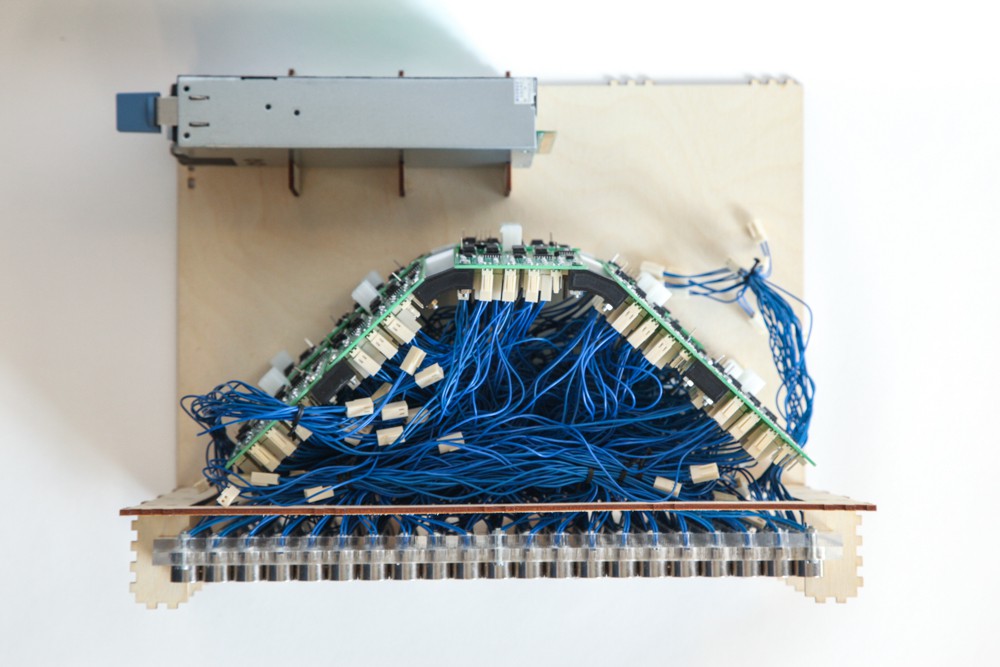
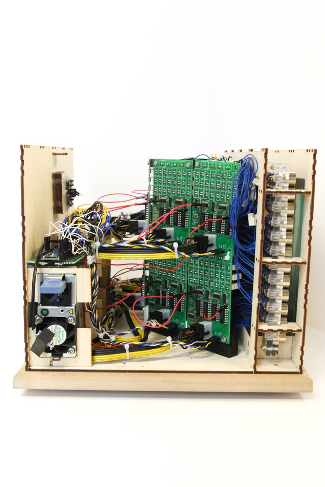
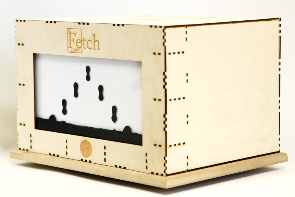
We are a group of students at the University of Oslo, that have designed and built a massive ferrofluid-display with 252 electromagnetic "pixels". The display has a 12x21 resolution (the closest we could get to 16:9 on our budget), and is currently in the final testing phase. The matrix will control ferrofluid and act as a reduced functionality display, meaning it has some limitations.
Most evident is the mechanical time-delays caused by slowness in the ferrofluid itself. It can only be moved "so fast", and it has to be moved up against gravity - meaning it's impossible to magically turn a pixel on out of nowhere. "So fast" is however fast enough that it falls down quite quickly due to gravity. This means we do not get any help from persistence of vision, like normal screens do. In addition, gravity makes sure that if you power a column of adjacent magnets: more ferrofluid will accumulate on the lower pixels, leaving the upper pixels drained. Therefore our system requirements basically state:
1. Each pixel must be individually powered.
2. The system must implement a way of applying different holding force for each pixel.
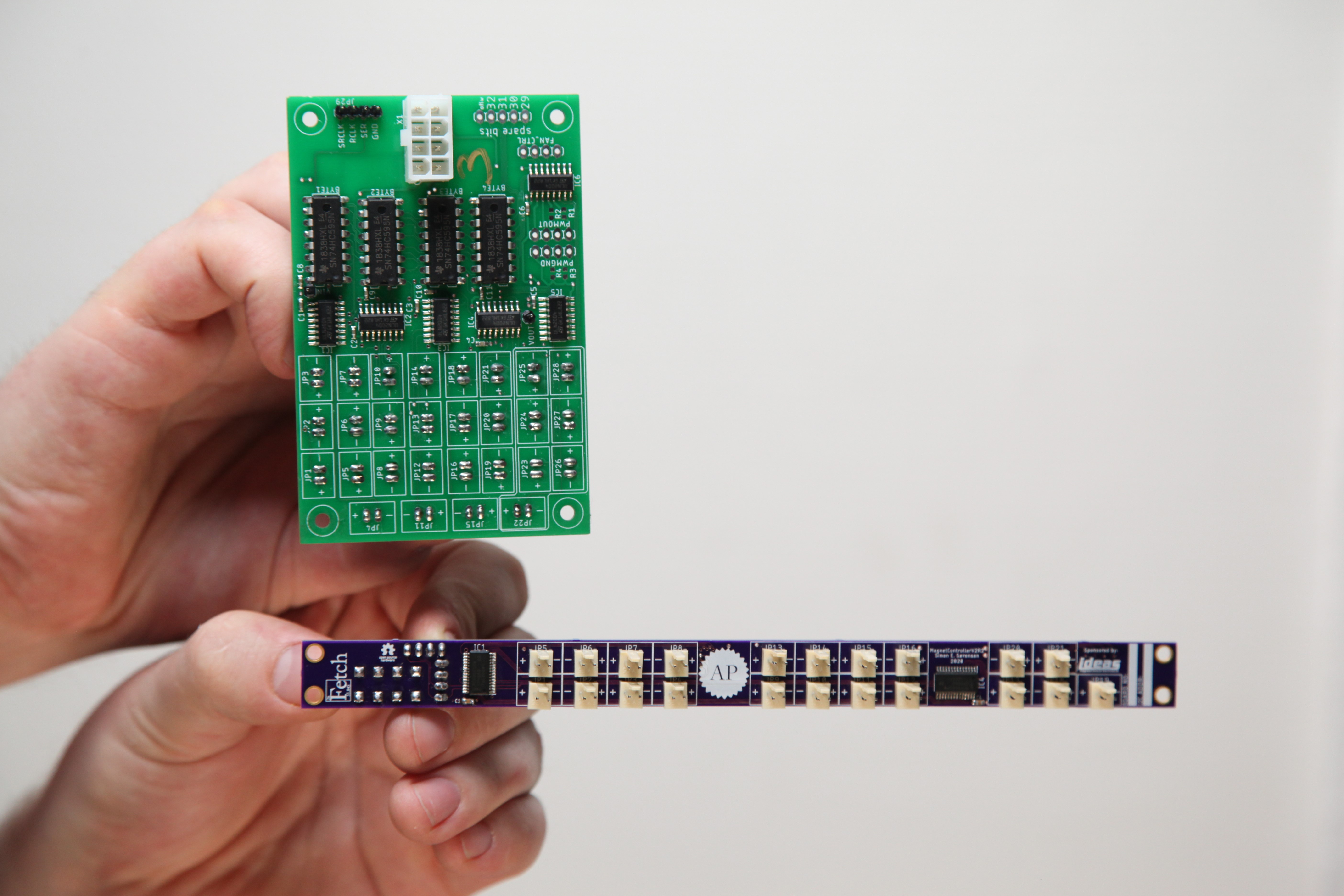
Now, for point 2, the obvious solution is to PWM modulate the signal that powers each magnet (as described in point 1). However, we are not aware of any microcontrollers with 252 PWM pins. We are not aware of an affordable microcontroller with 252 of any pin, really. So, first of all we have to figure out a way to expand however many pins we have to the amount of pins needed. The solution we use are serial->parallel shift-registers. That solves point 1, but snaps us out of the dreams we had about individual PWM functionality... Or does it? Well, the way this has been solved is to implement the PWM in software. This is not optimal at all, because it makes our PWM frequency dependent on the execution time of the main loop. However, with some recent upgrades we made it seems to run fast enough to give us some leeway in terms of frequency-jitter. There's more on the topic of fast code towards the end of this story, but for now, let's take a look at how the project has evolved.
Prototype (Arduino Mega based)
We were not sure how to do anything related to this project when we started, so the only logical thing to do was to start on a smaller scale than the 252-pixel "monster" that we had planned. Therefore we built a smaller, 6x6 prototype, hooked it up to a single driver-PCB (max 28 magnets, so we only connected 6x5 of them) to test how everything worked out. The results were surprisingly good, so we went ahead to commit to a design that we could use in the final display.
When we are done with the full scale display we may revisit the smaller version and make a separate project on that, since it's a lot cheaper and easier to reproduce for other ferrofluid enthusiasts.
Many hours of experimentation
From the time when we saw ourselves happy with the performance of our prototype to the point when our full-scale display was fully assembled a lot of time was spent experimenting with everything from circuitry to the actual ferrofluid tank itself. All of this is documented on our YouTube channel, and if you're interested in making your own ferrofluid display, we highly recommend that you check out those episodes, as we try to share all the pitfalls we've discovered.
Electronics Assembly and Full Integration Testing:
In our most recent video we integrate the full system and test it after first having assembled and tested the electronics.
Everything is open source, and the files can be found below. However, we do not recommend anyone to attempt to rebuild the project in its current state. The electronics especially require a big revision (version 2 will be started later this fall).
Code Optimization
As was evident in the video above, and as we discussed earlier in the article, the Arduino Mega is starting to get a bit overwhelmed by how we handle everything sequentially....
Read more » Applied Procrastination



 Anders Nielsen
 Stephen Holdaway
 monte
monte
 Neo
Neo
我需要找到这个项目的发明人,能给我提供联系方式吗?