Close
0%
0%

thumbMouse

Finger-mounted bluetooth pointer device using BlackBerry trackpad sensor, for avoiding shoulder/wrist pain from mouse/touchpad use.

Similar projects worth following
The motivation for thumbMouse is the muscle aching of shoulder or wrists that involves using the touchpad embedded on most laptops, which involves placing the right hand asymetrically to the left hand on the keyboard or a mouse which typically sits too far to the side and at a different height, which results in uneven posture.

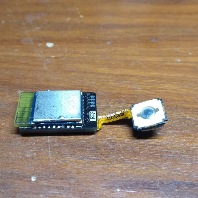
thumbMouse is a small Bluetooth device that attaches to your index finger and features a BlackBerry trackpad sensor, used for controlling the pointer by rolling your thumb over it. The trackpad itself also has a push button and thumbMouse supports up to four inputs for extra buttons (left, right, middle, etc). This allows you to control the pointer from any hand position and without requiring any arm/hand motion, allowing you to leave both hands on the keyboard while typing. thumbMouse also naturally adapts to right/left handedness.

For maximum control and comfort you can have one in each hand (one dedicated for scrolling and the other for pointing).

Challenge

If you use a laptop you may have found that using the touchpad involves placing your right hand, arm and shoulder in a different angle than your left. After some time this can lead to pain and even numbness due to nerve compression. An alternative is to use an external mouse but this also involves placing your right hand far from the keyboard and carries the same problems.

The main problem behind this, is that using your hand for pointer control gets in the way of maintaining a neutral and symmetric position on your keyboard, such as when you have your index fingers resting on the nubs of F and J keys.
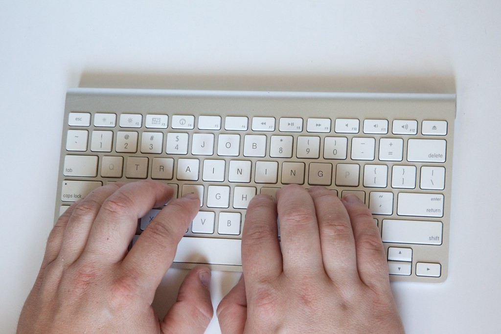
Besides the ergonomic aspect of this problem, a hand-controlled pointer wastes the extra dexterity available on your fingers: precise motion with a finger is easier than with your whole hand/arm.

In terms of accessibility, there are also limitations to current solutions: a universal mouse for left and right handed people implies either two different device models or ignoring the different grip from a left and right hand (mice are typically curved one way or the other).

Finally, there is an undeniable aspect related to individuals with limited mobility or dexterity, in case where full arm/hand use is not possible but thumb and index use is possible. While I have not addressed the problems of a particular ailment (this requires careful thought and consideration of a given disability and carries great responsibility to avoid false expectations), I believe it is possible to design a device that can be easily modified to conform to particular needs.

Proposed Solution

thumbMouse is designed around the BlackBerry trackpad family of sensors. These work exactly like the sensor found on optical mice, where images of the surface are analyzed directly in hardware to produce and estimation of planar motion based on the displacement of pixels on the image (this is usually called "optical flow"). The sensor simply reports an increment in X and Y coordinates. For the case of the BlackBerry trackpad, instead of sensing motion of the surface where you place your mouse it recognizes the motion of the finger over the sensor.

To provide a wireless solution using low-power approach, thumbMouse uses Bluetooth Low Energy (BLE) communication. The device itself acts as a Human Interface Device (HID) which is the standard protocol for mice and most input devices. This protocol is universally recognized not only by computers but also smartphones, regardless of its Operating System. To provide such a low-power and low-size solution, the nRF52832 chip (using a pre-existing module with chip antenna) is used.

As a wireless device requires its own power, thumbMouse also includes a battery and a USB based charging circuit.

To complete the device as a general purpose pointer, there's is support (via explicitly exposed PCB pads) for up to four I/O, as well as exposed 3.3V power and ground connections. As the trackpad itself embeds a push button in its back (you can press it and it will register the click), these extra I/O lines will mainly be used for adding other buttons found in mice such as left, right and middle click. However, given the ability of nRF chips to multiplex almost every pin to almost every peripheral, these inputs could be used to interface to analog sensors (including capacitive touch) or even I2C/SPI devices. This opens the possibility of extending the device in new ways, such as including an IMU.

The way to use thumbMouse is to wear it on your middle phalanx of your index finger and employ your thumb to operate the trackpad and thus control pointer motion. As the sensor has sufficient resolution, you can control it precisely. At the same time, by using pointer acceleration, a single swipe can make the pointer move across the entire screen with little effort.

Left/right/middle buttons can also be operated using your thumb or fingers from the other hand (for drag operations, for example). This operation allows...

Read more »

  • Working towards rev2

    Matias N.06/30/2020 at 21:51 1 comment

    So recently I've been focused on BicycleCompanion, which I also submitted to HackadayPrize, since as I mentioned in last log I hit a bump with current design based on NRF51822. I still have no idea why I couldn't get Bluetooth to work but having only 16KB of RAM makes me wonder if it would work at all.

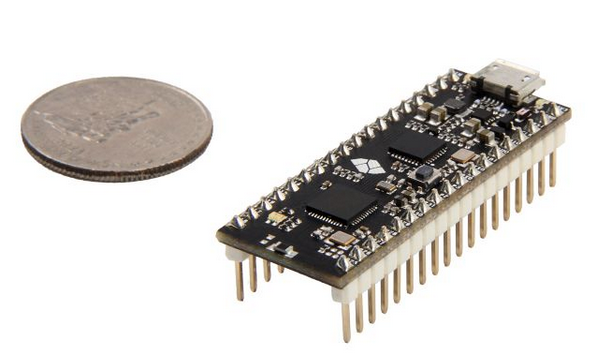
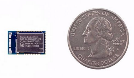
    Anyways, yesterday I woke up to a first good news: I received another very kind donation on KoFi from someone interested in seeing thumbmouse move forward. After considering what I should do with the funds I realized the best would be to buy both an evaluation board and a module for a newer Nordic chip. This way, I could properly test any code before I finalize the PCB design. Then, I would already have a proper module for the PCB. I first try to see which Nordic chip to aim for. While I think nrf52840 is a very good option, I couldn't find BLE module for it with castellated pads from a respectable source. Since I already had a bad experience with the other module due to this, this was a must. In the end I decided to go with nrf52832, which is mostly similar. I found that Seeedstudio had some nice cheap options for both evaluation board and module. I decided to buy:


  • MDBT42Q, which uses a chip antenna
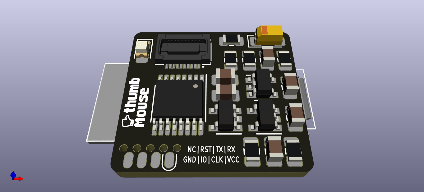
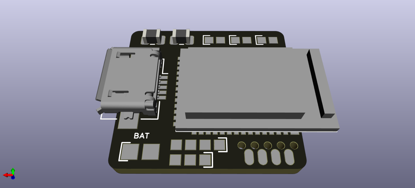
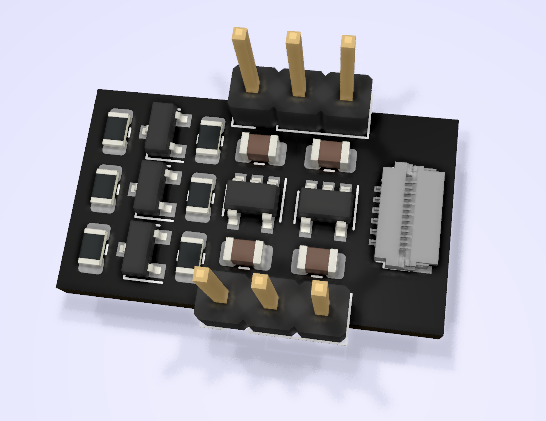
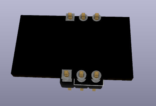
  • So, after ordering I decided to start revising the design I had, based on the SPI based BlackBerry trackpad series, to include this module. So far I have a reasonable layout of components without increasing the size too much, although I haven't put down traces yet. Right now the board looks something like this:

    The main changes are:
    • 20-pin FPC connector for 8250 series of trackpads (actually, I suspect many other models have the same pinout, will have to check)
    • Battery Charger IC, to charge via
    • Micro USB port
    • Voltage level translation IC: since I have many lines to translate between 3.3v and 2.8v I had to use this chip
    • Various pads exposing I/Os, VCC and GND for easy connection of switches, mouse wheel encoder or whatever one wants to add (someone mentioned a trackpoint, for example)
    • 18.8 x 17.3 mm in size (22.2 x 17.3 mm including the protruding BLE module). This is almost the same in length as rev1 but about 3mm wider. I think it is still small enough to be usable.

    And while taking a break from revising the design, I saw by chance that thubmouse was featured on hackaday! Really cool, aready got some feedback from there.

    The next step will probably be to buy some trackpads to check their size and see what is the best orientation for the connector. Anyways, as I have used cheap post por the Seeedstudio purchase, it may take about 30 days for stuff to arrive. So, I will probably have to wait for that to continue. My plan will probably be to again use Zephyr to have a quick test and then finalize the design. However, I'm considering working on adding Bluetooth handling on NuttX for the nRF52832, and base the code on that. That will take some time though, but I think it would be cool to do. However, once I have the design ready I can already order and test again with Zephyr. So expect this to be done not long after I receive these boards.

  • Troubles

    Matias N.06/20/2020 at 03:36 0 comments

    Completing the build

    Last tests of thumbmouse were made using the board as a breakout for the sensor: the BLE module was not soldered and I connected the PCB via flying wires to an external Nucleo board (as you can see in last post's video). 

    After this test, the next step was to solder the BLE module. This was quite a difficult thing since the BLE module has the pads only at the bottom and not to the sides. Also, this thing is damn TINY. I think for this module it would have been better to use solder paste and a stencil but I didn't want to spend too much for this board at this point.

    So, I soldered the BLE module using the iron and I started getting bridges below which were really difficult to correct. Eventually I accepted that I had to use hot air to try to remove it. This took me long time since the module sucked a lot of heat. Eventually I managed to remove it but I ripped a pad of my PCB in the process. So, know I needed to populate the tiny PCB for the third time! Also, I didn't know if I cooked the module in the process or not.


    First tests

    After soldering the third board (this time it went much better and faster, at least it was good practice), I tried to do a little test with Zephyr RTOS (which I never used before, as I'm used to NuttX). It took me some time to adapt a similar board based also on NRF51822 but eventually I managed to control the LED. However, it was a blink example and the LED would not turn off. I started debugging and found that the board hung when going to sleep between LED turning on and off. This was really strange and after many hours of debugging, since I didn't know for sure this wasn't due to the module being ruined by the heat, I managed to get a blinky test using platformio, which uses the mBed framework. Surpisingly, the LED blinked. Debugging the code, I could see that it used the same RTC1 peripheral to control the sleep(). So, something must be wrong on Zephyr. This led to another set of long debugging hours, e-mailing Zephyr devs, opening an issue, etc. Then, for some reason I remembered seeing some errata documents from Nordic and decided to check if there wasn't actually a bug in the silicon which affected this module (but not other more popular ones which were working on Zephyr). To my surprise, there was indeed a BIG bug, whereas if you didn't set some magic value to some magic address NO PERIPHERALS WOULD TURN ON. I went back to mBed code and indeed this magic code was there. So, I transplanted the code to Zephyr and finally the damn LED blinked!

    [video-to-apng output image]

    The bad thing is that even now that this was working, no Bluetooth examples seemed to work (I can't see the advertisements on my phone). Again, I'm sure it is not a hardware failure since the original firmware from Nordic is working and I can see it from my phone. So, I'm guessing there are other bugs affecting this chip or at least Zephyr has some problem with this model. Since I don't really understand much about low-level Bluetooth radio handling, I feel this is a bit out of my reach now. Moreover, I'm starting to feel that it was not a good choice to use this module (considering also the 16KB of SRAM it has).

    What now?

    So, unless Zephyr devs manage to point me in the right direction for this bug, I think I will most likely have to focus on a second revision of the hardware (which I already started to use the other trackpad series, include battery charging IC, regulator, etc), but this time using a newer module, based on NRF52 series and with easy to solder leads.

    However, I would need some help funding this second revision so if you're interested in making this happen, you can help by donating here: https://ko-fi.com/protobits

  • Trackpad is alive!

    Matias N.06/04/2020 at 19:57 0 comments

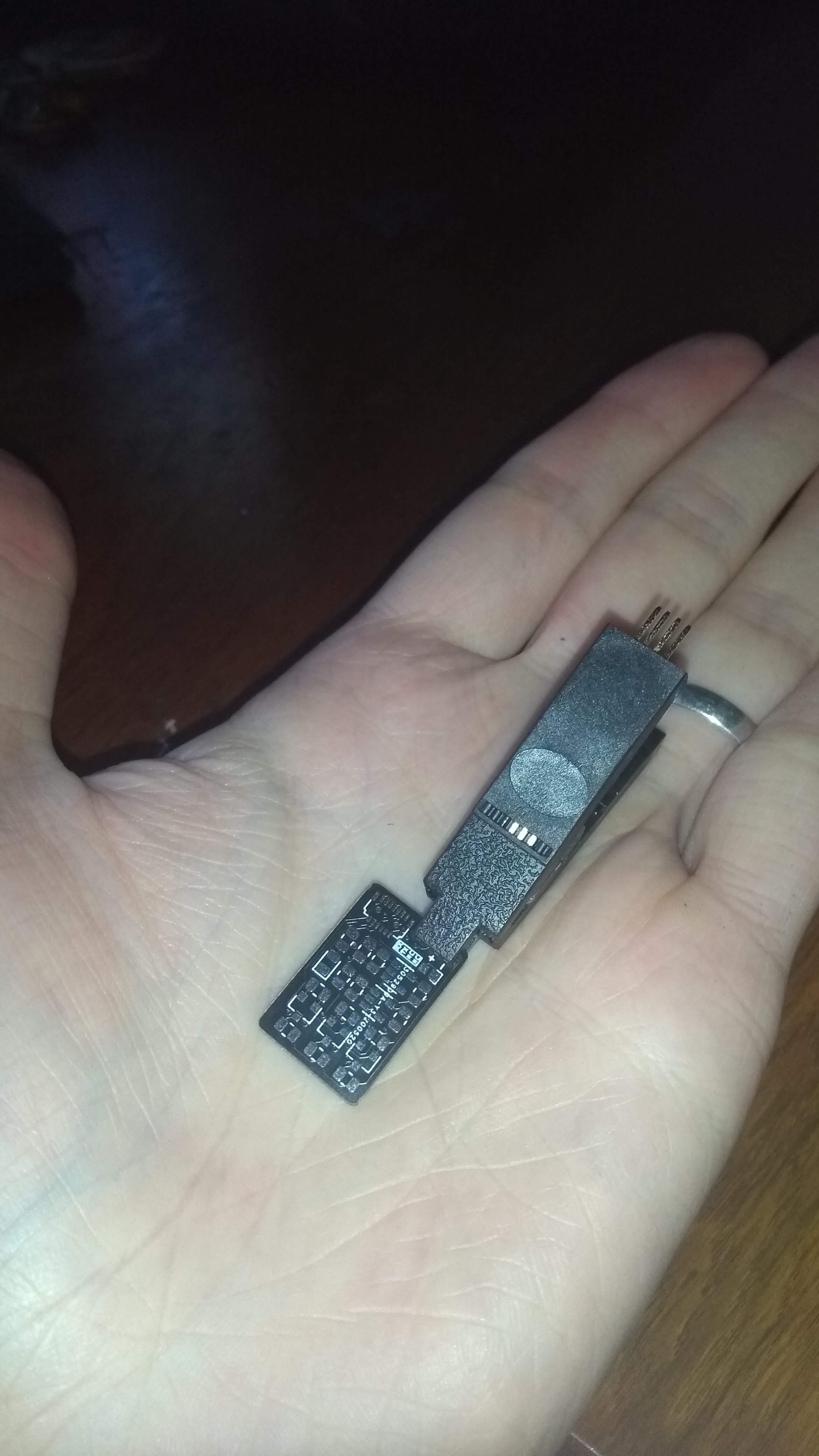
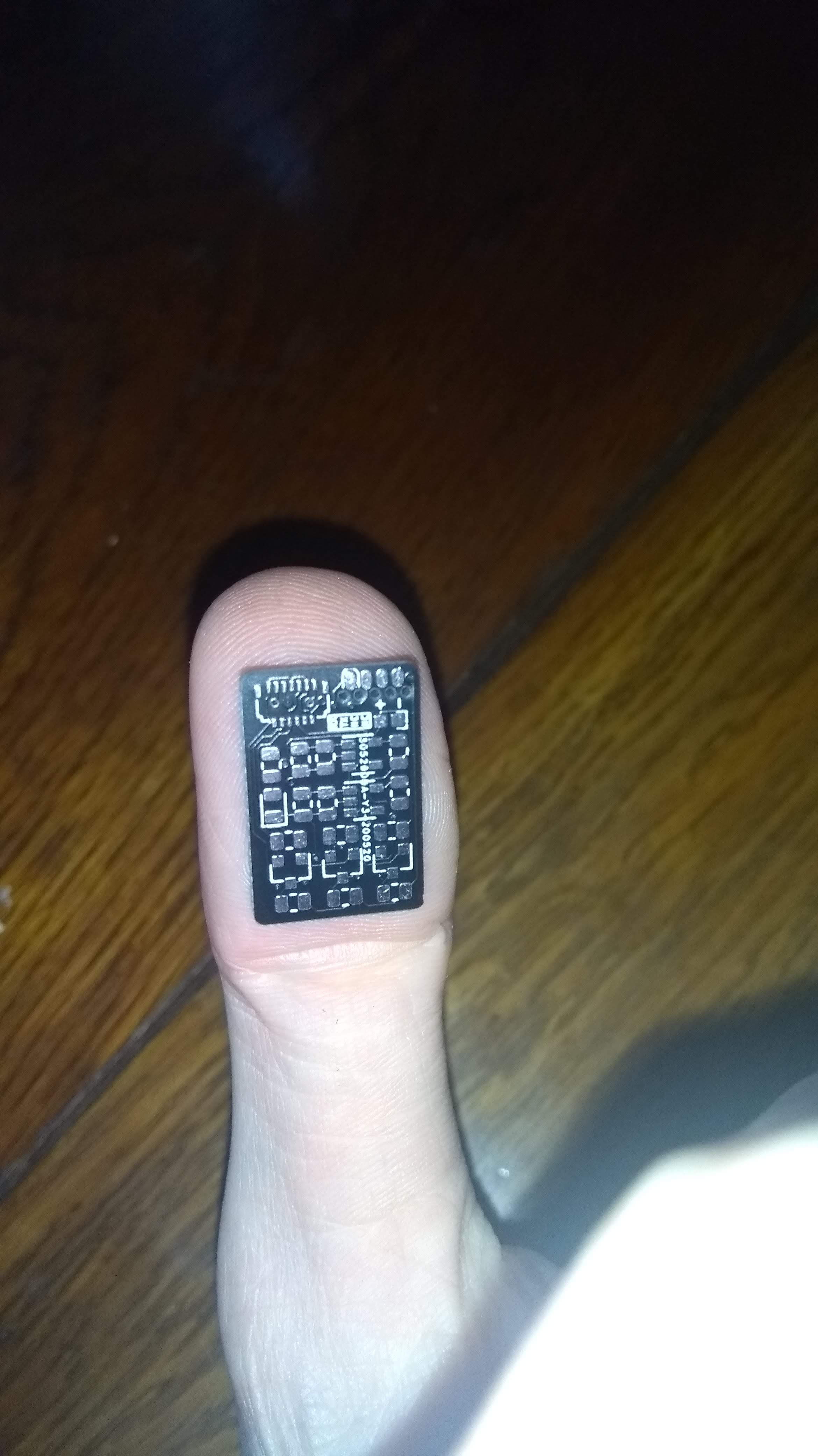
    Today I finally received the PCBs (DHL took them for a trip to the other side of town for a few days). I knew it would be tiny but I was really impressed with how small it was. The text indicating the SOICbite pinout was even unreadable.

    In fact, I had to test if it was correct to call it "thumbmouse". It seems it is.

    While I was still waiting for the batch of passives I ordered, since I had some resistors and capacitors of acceptable values I decided to go ahead and solder this. I still don't have the BLE module (it is sleeping in some post office storage building for some days now), I figured it would be best to first try and test this via an external MCU, since I would not want to solder the BLE module to a useless board since it was a bit expensive.
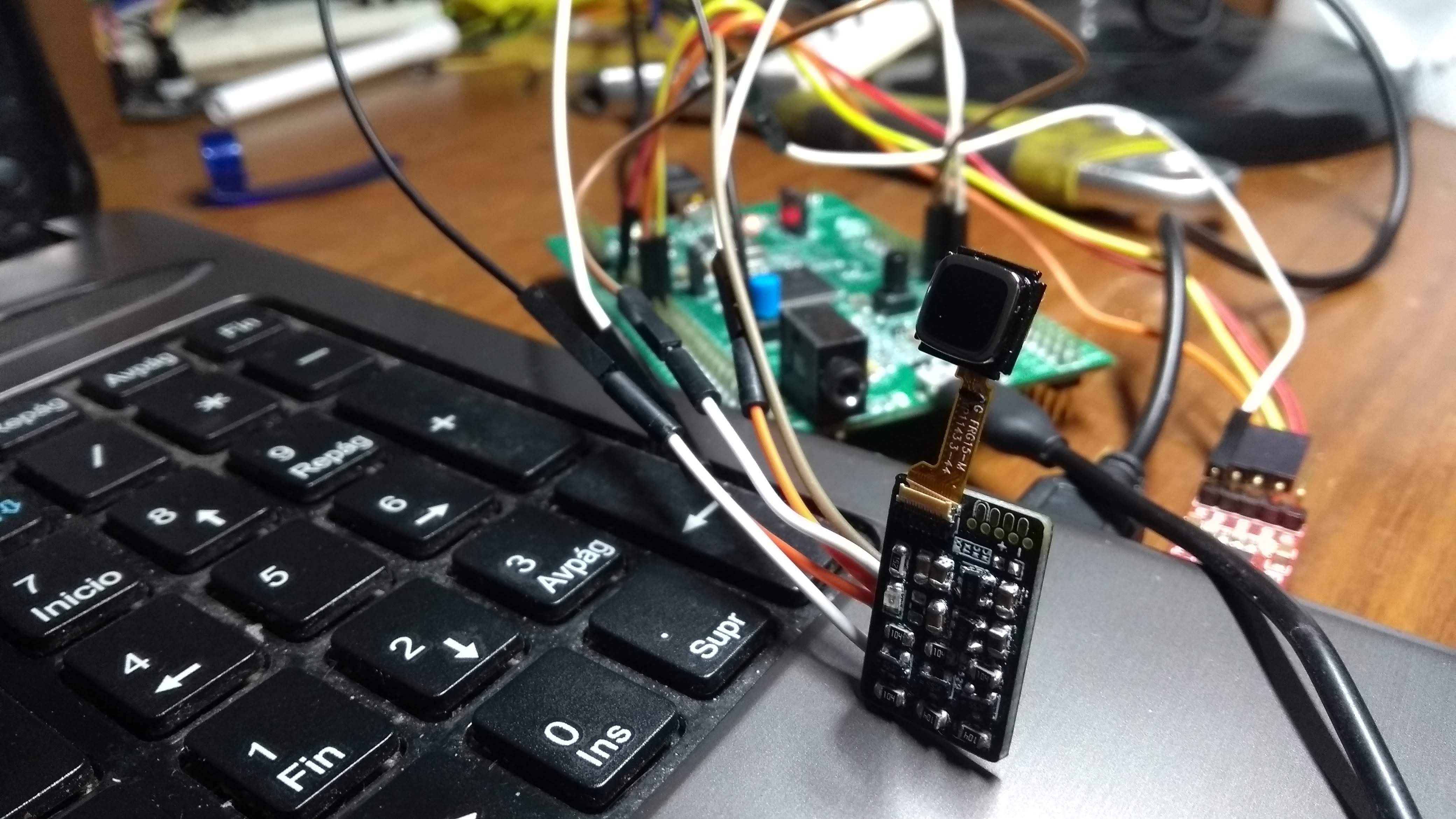
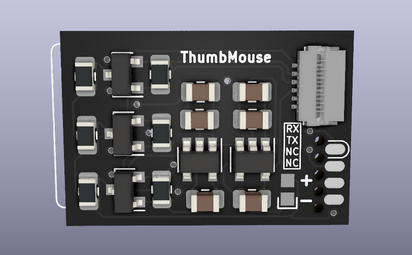
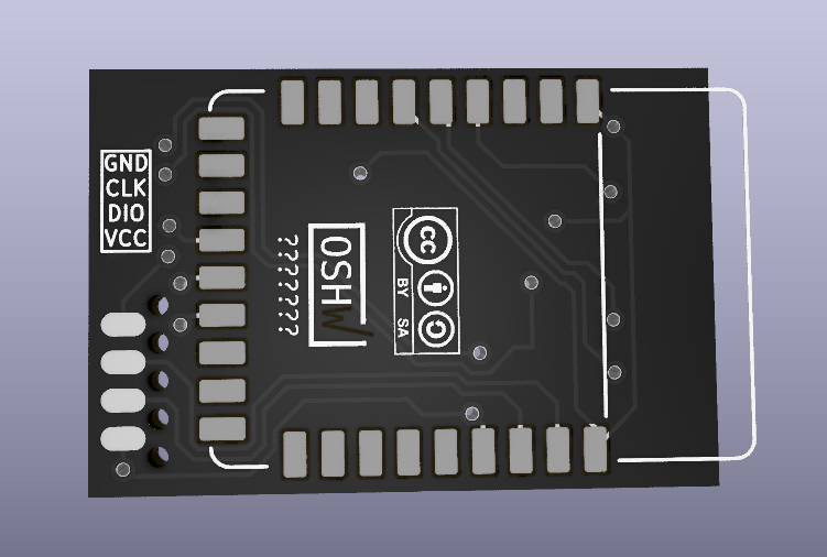
    I decided to use solder paste for this, since it would be good practice and also the FPC connector had a really small pitch and not so accessible pins. The solder paste I bough seems to be a bit dry (it may be since it is a bit cold here and it may require higher ambient temperature, or it is also possible it was not stored correctly). It was quite tough to apply the paste since it would not stick to the pads, so this was a bit messy. I placed all components and used hot air gun to melt the paste. This worked more or less OK, although I melted the plastic base of the microscope and the PCB got stuck. When I tried to take the PCB off the base I messed up and moved a lot of components. So, I had to manually fix everything with the iron and fix a few shorts. In the end it seems to work: 2v8 and 1v8 voltages were output correctly and the level-shifting worked reasonably (which about 300/400mv drop.

    I decided to use a STM32F407 discovery board and an Arduino sketch to test. I had some difficulties at first which I thought was due to the low voltage of my USB port (it outputs 4.5v, which for the 3v regulator ends up being around 2.9v, not enough for the 2.8v regulator. I ended using the 3.3v output of the USB-serial converter which was  correct. However, it was still not working. In the end it was what I suspected: the Arduino STM32duino libraries chose a very wierd combination of SDA/SCL pins and I had to go into the headers to find this (:facepalm:).


    With the communication working, I used the Arduino sketch I had written a while ago for the protoboard version and I added Mouse emulation support. Finally, I had thumbmouse working as a mouse for my PC.

    So now, the next step will be to solder the BLE module when it arrives and try to have this working over Bluetooth. It will not be fully wireless actually unless I use a coin-cell, which means I will probably power it from the SOICbite connection. I will test the power draw of the sensor to see if it is not too power hungry for the coin-cell. Anyways, next version based on 8520 trackpad will definitely use a rechargeable li-po battery.

  • Connector for trackpad working

    Matias N.05/27/2020 at 19:50 4 comments

    Today I received Mouser order containing necessary components for building the current design of the thumbmouse prototype (based on BlackBerry 9900 trackpad). This trackpad has a thirteen contact FPC with 0.3mm pitch (tiny!). It is supposed to have same functionality as the 9800 (also thirteen contacts but with a more workable 0.4 mm pitch) but I could not find a suitable connector for it. On Mouser I found one connector that was supposed to be compatible with the 9900 so I targeted this version for starting.

    Some time after ordering I realized from the connector datasheet that due to the shape of the FPC  it wasn't an exact match for the connector so I realized I would have to modify it (not ideal). Today I finally got the test the compatibility. I had to cut the side lips of the FPC which would not let me insert it fully. You can see the surgery I had to perform in the following video (using a nail clipper):

    This allowed me to insert it correctly but I had to be sure that the FPC mated correctly with the connector's contacts. I checked continuity using the microscope and everything seemed to be OK! (no sound from the microscope, but believe me it beeped as expected). It is incredibly how fragile the connector is, after pressing the tester leads against it made a bunch of bumps.

    So, with this I'm now fairly confident this should work. I'm now waiting for the PCBs and BLE module which should arrive this week. Finally I need to get the passives and SOIC clamp in order to flash/debug the board using the SOICbite connector I included in the board.

    While waiting for all things to arrive I actually started designing another version of thumbmouse targeting the 8520 series of trackpads which use a more standard connector which would not require any adaptation. I will continue to iterate this version with everything I learn from this.

  • ThumbMouse prototype!

    Matias N.05/16/2020 at 21:28 0 comments

    Well, the previous breakout finally ended up being an actual prototype design for thumbmouse. I realized that adding a BLE Module already completed the design. This way I can even have a prototype to play with instead of just the breakout. Behold the result:

    On the back, a Seeed BLE Micro Module (NRF51822) would be mounted. The connector on the edge is the SOICbite which allows for SWD connection (and UART) without a connector. The power pads on the front are to supply power via a coin-cell battery (max voltage 3.6v). There's no 3.3v regulator on board to supply from battery directly (or external regulator).

    I hope I didn't make any stupid mistake as I designed the board for this module while I never even actually played with any nordic chip.

  • Breakout board

    Matias N.05/16/2020 at 00:31 0 comments

    I've been working on BicycleCompanion lately, and I'm close to ordering components to build a first prototype. With any luck, I will have something done for the HackadayPrize. I decided to order the basic parts to make a BlackBerry 9900 Trackpad module as well, now that I finally found a (supposedly) suitable connector. I'm thinking about a breakout that can be placed in the middle of a protoboard, but using castellated pads which would allow for soldering on top of pcb directly.
    What do you think?

    PS: any help via KoFi is highly appreciated, it really helps me buy components and order PCBs for these projects. It goes without saying that I intend to publish the designs as open-source.
    Buy Me a Coffee at ko-fi.com

  • Project on hold

    Matias N.10/04/2019 at 22:34 0 comments

    While I have a protoype working, as I mentioned previously, I have an issue of not having an appropriate connector for the two sensor modules I have. I actually found ONE manufacturer (I-Pex) that provides one that could work for one of the two models. I contacted them and requested a sample, however while they were nice it was basically "we cannot pay for shipping this product if you are not developing something commercially and have your own company". So, at the moment, I guess I will not get a connector.

    The remaining option is to design a footprint for the sensor which has little holes in the pads. In theory I could add solder to the PCB and FPC and then melt them together this way, but it is a bit tricky and I'm not sure it will work.

    I have written the schematic for the circuit though: I found appropriate PSU ICs for the 1.8v and 2.85v supplies and also included the MOSFETs for logic-level conversion. I have not yet designed the PCB as I'm not currently motivated to continue this in this way. In any case, I will most likely finish the PCB design in the future, when I make an order on digikey for some other parts and then I can order the required components for this board. Then, I will probably build a complete protoype, at least to finish this with something built. I will eventually decide if there's enough interest to work on this further or not.

    In reality I lately became more motivated in picking up my BicycleCompanion project, for which I already have a working protoype. I want to do a second version with many new features and also with several improvements. Thus, I will direct my focus there at the moment.

    In any case, let me know if you have any particular interest in this project or any questions or comments.

  • Functional Proof of Concept

    Matias N.08/25/2019 at 18:01 1 comment

    I have the trackpad working as a mouse! I will try to make a video of it, but it is difficult to show both the trackpad being used and the pointer moving on the screen. But, it indeed works. I'm amazed on how sensitive and precise it is. I'm actually able to move across the whole screen without much effort and at the same time, make small and precise movements. I'm not sure if Linux is adding some sort of acceleration to the pointer, but it works perfectly.

    At the moment I'm polling the sensor via I2C since my interrupt line is not being converted to 3.3v (I'm reading the 1.8v line directly) and it does not work reliably as one would expect. Fixing this will eventually enable low-power reading of the sensor.

    With this result I'm actually deciding on going ahead and design a PCB with everything needed for a wired version: USB connector, the two power supplies, logic-level converter and MCU (not sure if STM32F103, I might go with some STM32L MCU to eventually have a low-power design ready for a wireless version). I will also need some way of reading button presses. I will probably better to have capacitive touch buttons than mechanical ones, since I imagine it will be more comfortable. Also, I need to design this so that the device is not too big and I can design a part to be 3D printed to mount the whole thing on a finger.

    Anyway, there's a slight issue with this: I need to find an appropriate connector for the sensor. I found some shady vendors on strange sites, selling blackberry parts. I would like to find something that I can buy from a reputable source such as digikey or similar ones. I don't really know if this kind of connector is supposed to be more or less standard or if it is custom-made for blackberry (seems unlikely). If you could help identifying I would be really thankful!!

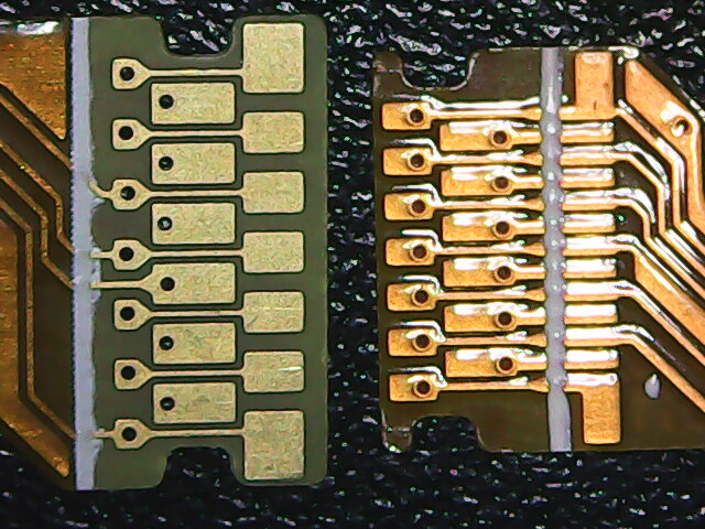
    Here's a picture of the BlackBerry 9800 sensor (the one I'm using) on the left, and a 9900 sensor on the right. It would be cool to find both, but I need at least for the 9800 one:

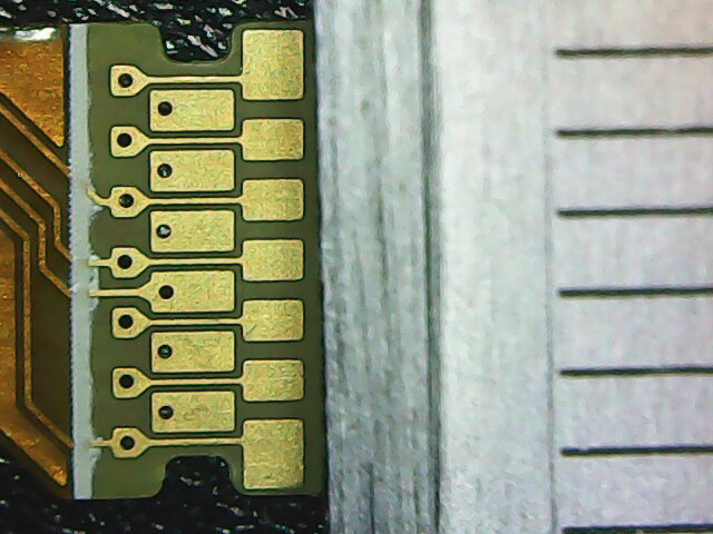
    And here's a picture with a caliper included, for scale (each tick is a milimiter). So it is about 5mm from extreme contact to the other (and there are 13 contacts). So I figure the 9800 sensor has a ~0.4mm pitch connector:
  • Success!

    Matias N.08/23/2019 at 23:15 1 comment

    Last few days I made some considerable advances so this will probably be a long post. TLDR: trackpad works!


    Trackball

    First thing I received was the blackberry trackball evaluation module. Since my expectation was that it would not be very accurate as a mouse replacement, I limited myself to simply analyze what was the actual resolution of the device. After connecting my cheap-o logical analyzer to the relevant outputs, I could see that there were around 9 pulses per one complete sweep of the finger on the ball (ie. the maximum that you could move the finger in one move). If you count edges, you then get about 18 counts. As expected this is a bit low. In fact, I tested only slightly moving the finger and indeed it required a bit of motion to get the first pulse.

    In conclusion, this kind of interface is more to either replace a mouse scroll wheel or for other kind of projects altogether. For example, it could be used for navigating a GUI displayed on a small screen, avoiding the need for four buttons.

    Trackpad

    Now this is where it gets interesting. I was eager to try these modules and see what could I get from them. I bought four units: two BB9900 trackpads, and two BB9800. As mentioned in the previous log, these have 13-contact flexible PCB connectors. From my research, these present a I2C interface, instead of the SPI used in other models. Still, it was supposed to implement a similar register map than that of ADNS3060 optical mouse sensors. One extra difficulty in these models, though, is that it requires both a 2.85v supply for the sensor itself and 1.8v for the logic. This of course also means it requires a level-shifter to map 3.3v <-> 1.8v.

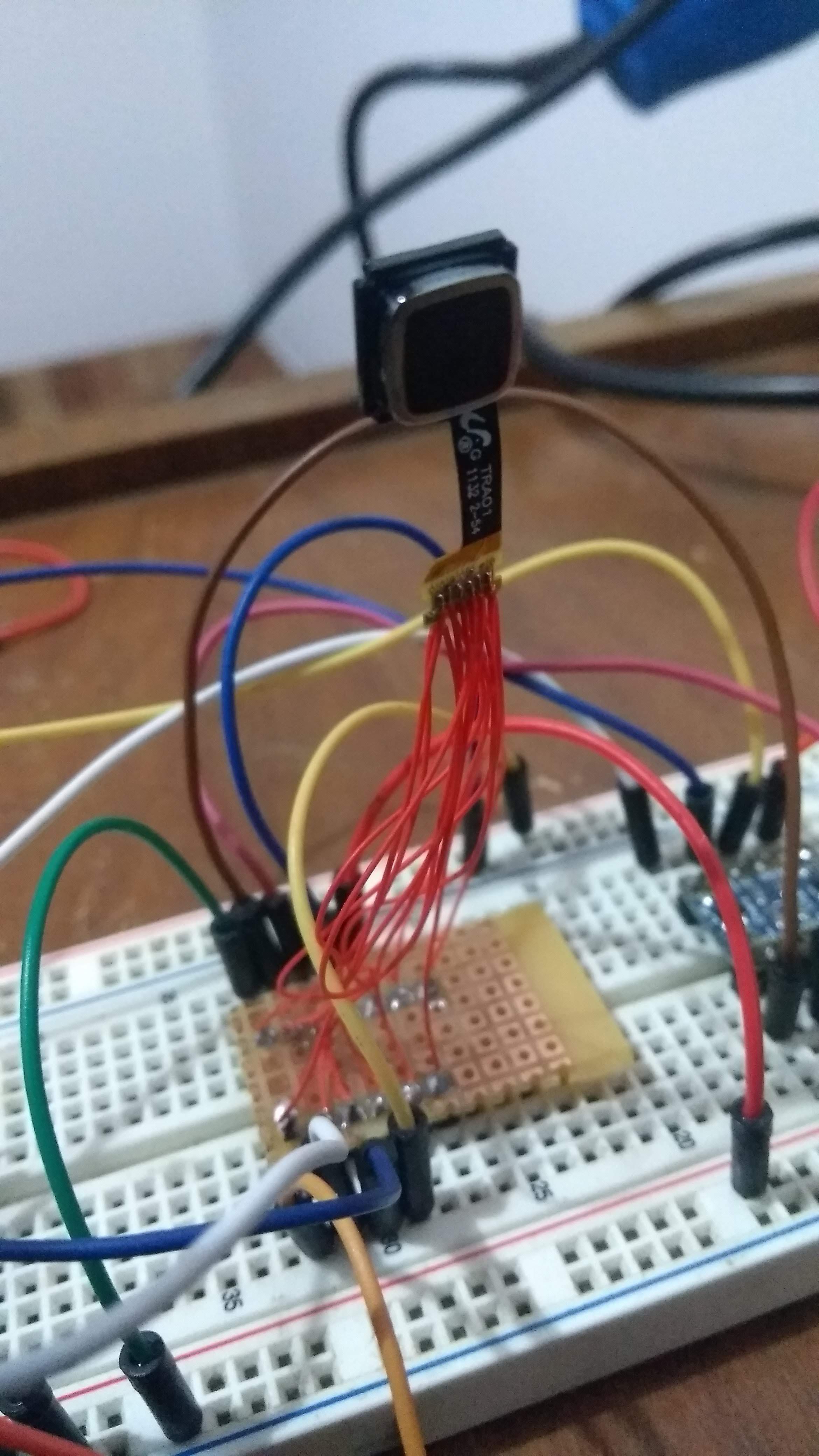
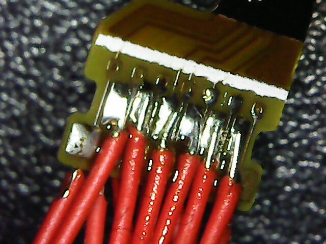
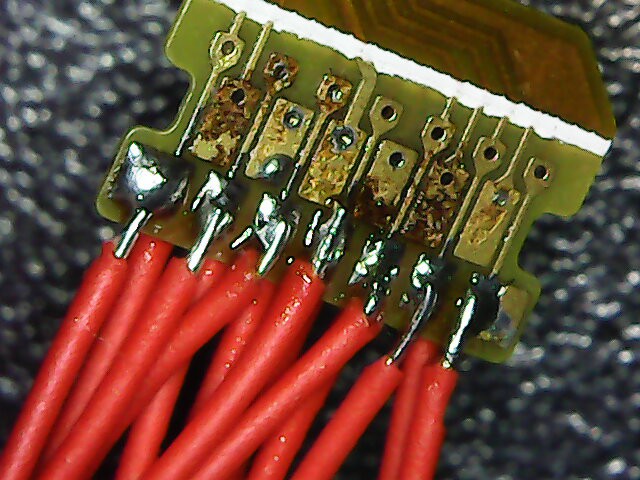
    So, the first task was to solder some tiny wires to the connector and make a DIP-like module for it, so that I could place it on the breadboard. While I actually had a digital microscope on the way, I gave it a try in soldered the wires with the naked eye. I must say it ended up quite nice. Here's a picture with the microscope of the job done:

    The brown part is some leftover flux. Or maybe it is a bit of burnt substrate, but it did not damage any of the fine traces. Also, I verified that there were no shorts. The module then looks something like this:

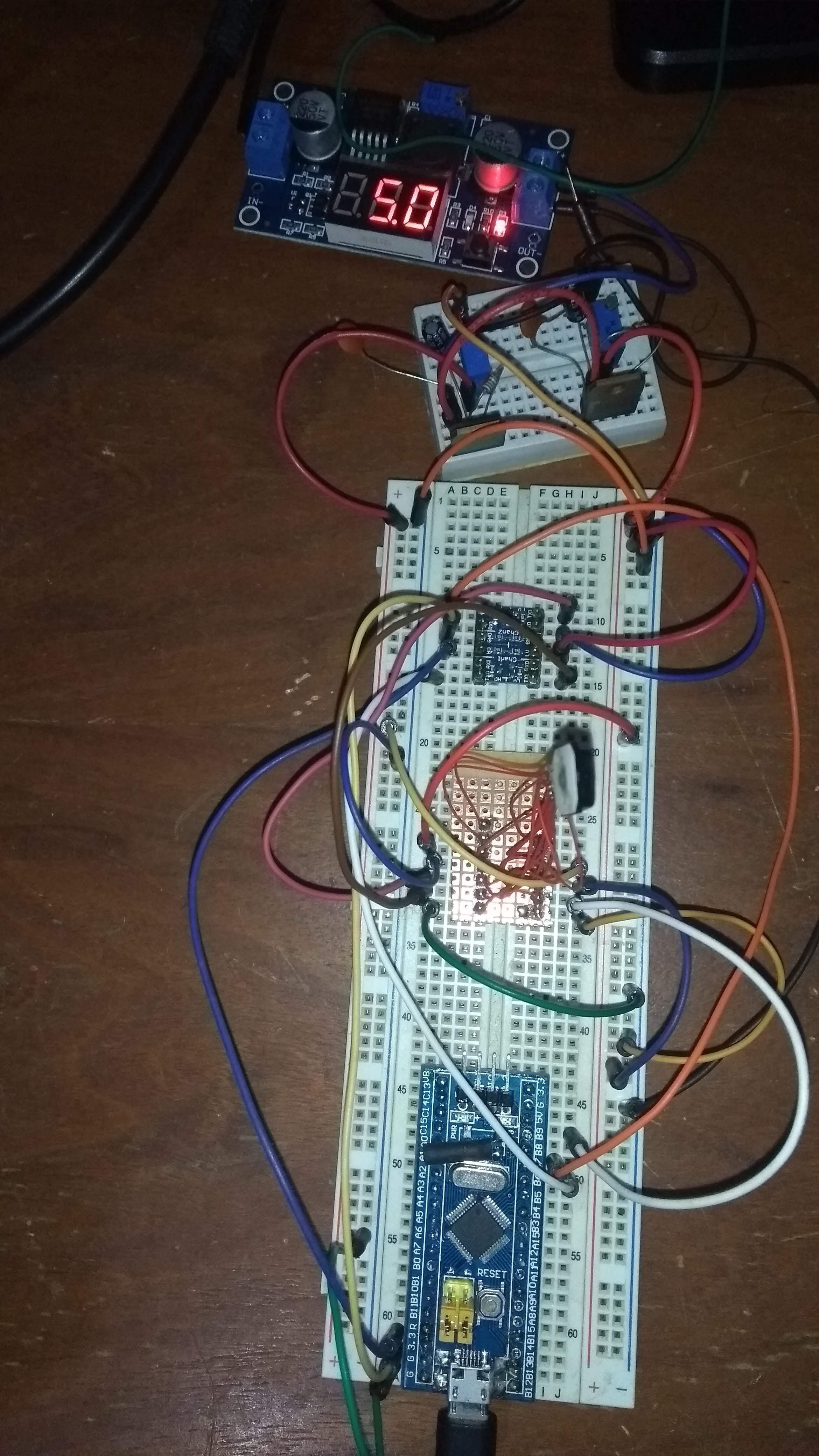
    The second step was to build the pair of power-supplies. Using an switching adjustable power supply (my new low-cost bench PSU at the moment), I converted from a 12v wall adapter to regulated 5.0v. Then, I've built the 2.85v and 1.8v supplies using a pair of LM317's and a small breadboard. I then wired the supplies to the module and used the logic-level converter to map the SCL and SDA lines.

    For testing I bought a BluePill board (STM32F103) but for some reason USB did not work (even after the R10 resistor fix). I then moved to an Arduino Pro Mini for initial testing. Later on, I re-used my old BluePill (which lacked the USB connecter) and transferred the malfunctioning board's connector towards the old board.

    The complete test setup can be seen in the following photo:

    Interfacing with the module

    At first I encountered many problems which led me to think that it just was not possible to talk to the board. Maybe the pinout wasn't correct. Maybe this model was different. Anyways, after lots of trying I finally found that I had some wires setup wrong in the breadboard. But that was not all. While playing with the wires and running an I2C device scanner Arduino example, I suddenly got a response from a device with a 0x3B address. Then, after playing with the wires again I got a 0x33 address instead. At first I assumed it was noise in the line, but it was actually pretty consistent. Finally, I concluded that depending on the assigned SHUTDOWN pin value, and after resetting the module, it presented itself with either one of these addresses. I've tested for the expected motion registers and concluded that the one that worked was the 0x3B one, so I left the wires for that case.

    Once I got that working it all went pretty well. From my tests, it seems that it...

    Read more »

  • Of trackballs and trackpads

    Matias N.08/12/2019 at 20:03 1 comment

    The TrackBall

    I have a BlackBerry trackball module on its way to start tests with that. This module includes the appropriate hall sensors to read the rolling magnets which allow to detect the ball motion. Also, it includes a series of LEDs and a touchpad button beneath the trackball.

    https://s15-us2.startpage.com/cgi-bin/serveimage?url=https%3A%2F%2Fae01.alicdn.com%2Fkf%2FHTB1BSr2JFXXXXbdXVXXq6xXFXXXn%2FICSH044A-ICSTATION-Blackberry-Trackball-Breakout-Board.jpg_640x640.jpg&sp=451957bbba26b013761e43b766f563dc&anticache=432953

    After looking up some videos and reading up on its performance, I expect it to be a bit underwhelming. I've read that it can detect about 9 pulses per full revolution, which does not seem to be very much. It is actually a strange design, since the button has four magnets and four sensors, where there's actually 2DoF. For some reason, instead of designing this to have a quadrature encoder ouput (where for each axis, we have to out-of-phase square waves, thus having 4x resolution if counting all flanks), it works by only activating one of the rollers corresponding to the motion direction. This means that only one hall sensor is activated per axis motion, and simply generates pulses.

    Anyway, I was more or less expecting this and I mostly want to test this to see if it is worth using in combination for a trackpad or maybe even in some other projects.

    The TrackPad

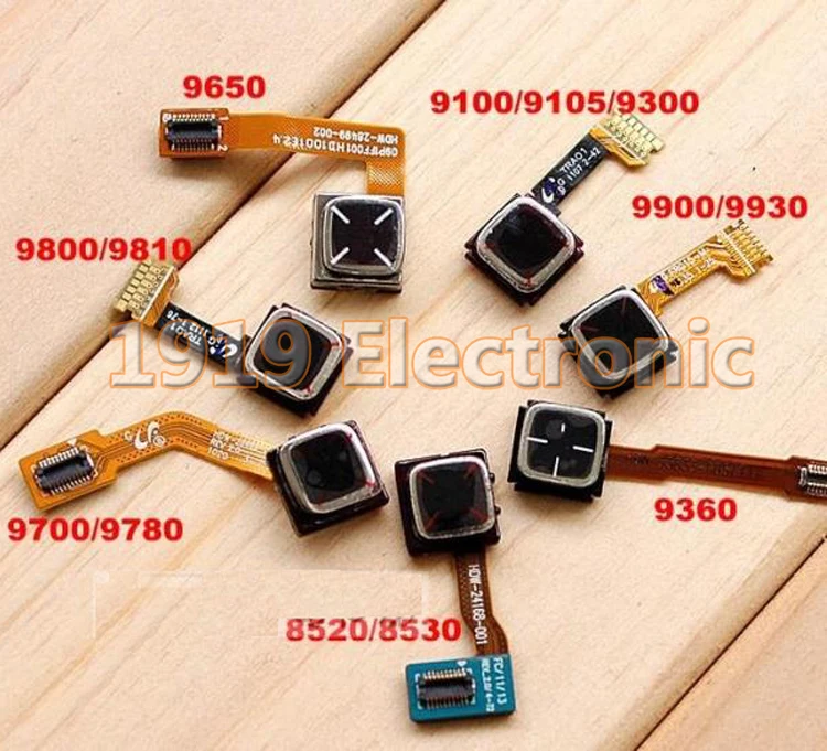
    When looking for spare BlackBerry parts, I saw that the trackpad is actually quite common since it was used in many more models. It is not much more expensive either. From what I've seen (it is difficult to find precise information), all trackpads work by emiting an IR light into the finger surface, which is then captured by an IR sensor which is able to compute delta motion of the surface. This is actually how old optical mouses worked. In fact, it seems that the registers it exposes actually conform with the comon ADNS3060 module.https://ae01.alicdn.com/kf/HTB1F3o9RXXXXXakXFXXq6xXFXXXv/Trackpad-Trackball-Joystick-Mid-Middle-Navigation-Home-Key-Button-Flex-Cable-For-BlackBerry-9700-9780-9900.jpg

    The difficult part is that there are many different modules used in various BlackBerry phones. Some use a surface connector and others directly expose the pads, in order to insert the tip into a surface connector. Also, it is difficult to find actual pinout for each, but I managed to unify information from different pages (and, mostly, from this project https://vlukash.com/2019/01/15/trackpad-in-keycap-corne-crkbd-keyboard/ which provides a lot of good information, including pinouts, schematics and code). In the end, I managed to build a list of interchangeable modules, but from these I have pinout for only three groups (one with connector, other two with exposed flex PCB pads). The first group of modules (used in crkbd project, linked above) works over SPI, whereas the other two work over I2C. Moreover, it would appears that the latter include a LED and button. Finally, these also appear to be more modern, since they are featured in the latter BlackBerry phones.

    I'm going to try to have a sample of a few of these. I prefer the exposed PCB pad version, since it would be easier to solder wires to it. The downside is that these appear to require not only a 2.85v regulator, but also a 1.8v for the logic.

    Pinouts:

    The following is a list (number is pin number, not yet clear which pin is pin 1) of pin assignments of intercompatible modules.

    9900/9930/9850/9860 series:

    Flex PCB, with exposed pads:

    1. DOME_A Dome Switch A
    2. DOME_B Dome Switch B
    3. LED- LED Cathode
    4. LED+ LED Anode
    5. VDDIO Supply voltage for I/O pads
    6. VDDA Operating Voltage supply
    7. GND_CSP CSP Ground
    8. NRST Resets chips
    9. IO_MISO_SDA Bidirectional open drain serial data
    10. MOTION Motion Interrupt
    11. IO_CLK Clock for serial port
    12. GND_ISOLATED Isolated Ground
    13. SHUTDOWN Low Iddq Enable

    9800/9810/9100/9105/9300 series:

    Also Flex PCB, with exposed pads. Appears to have same pinout from above series, however the footprint of the pads is different (pads are bigger):

    1. KEYOUT
    2. KEYIN
    3. GND
    4. VSYS
    5. V1_8
    6. V2_85
    7. GND
    8. RST_N
    9. SDA
    10. MOTION_N
    11. SCL
    12. GND
    13. SHTDOWN

    8520/8530 series:

    The conector required to mate with this module is the following: DF30FB-20DS-0.4V

    1. GND
    2. SIG(3)
    3. NC
    4. SIG(2)/INT
    5. RESET
    6. SIG(1)
    7. SHTDOWN
    8. SIG(0)
    9. CS
    10. 2.85v (220ohm)
    11. CLK
    12. 2.85v
    13. SDI
    14. GND (220ohm)
    15. SDO
    16. KEY_OUT
    17. MOTION
    18. KEY_IN
    19. 2.85v
    20. GND

View all 10 project logs

Enjoy this project?

Share

Discussions

Mike Hansen wrote 06/07/2023 at 00:12 point

Hello, I came across this project searching for a adaptive equipment for people with disabilities looking for alternative input devices for a desktop computer. Is there a way I can contact you about this through email?

  Are you sure? yes | no

lisa wrote 06/21/2022 at 13:03 point

I have had a similar idea for years, I even bought some Blackberry sensors, but never got around to it with all my other projects on the go!
I hate trackpads and always use a Logitech trackball. This is bulky when travelling with a thin laptop. My idea was to make something with similar shape to the Logitech device but very flat, BLE or BT connectivity and ergonomically contoured with optical thumb track device, the other mouse buttons and possibly a second optical track device for scrolling.
I.e. lay your hand not quite flat on a desk with the fingers and thumb slightly apart. The thumb track device would be under the thumb, buttons would be under the index and middle fingers and between them another optical track device for scrolling.

  Are you sure? yes | no

agilum wrote 11/04/2021 at 08:32 point

Hi Matias, 


I would like to use I2C version  of BB trackpad ( 9360 ) with 14 pin connector as a pointing device for keyboard project. Unfortunately I could not find any info about that. Could You please point me to the right source of information regarding I2C versions of trackpads ? I have  seen Your implementation of BB9900 at gitlab but BB9360 has different connector. 

Thank You in advance 

  Are you sure? yes | no

Px wrote 06/16/2021 at 13:36 point

I really like the idea and it's sad that nothing like this is available yet. Would you mind sharing your firmware and some information where to source the connectors for the trackpad? I guess you have seen the ozon smart ring. Something similar to their ring design would be great! Like a triangle housing the sensor and connector, held in place by an elastic band.  That could be connected to a wristband with the rest of the hardware, like you mentioned on twitter. I think that's a better solution than trying to fit everything on the finger.

  Are you sure? yes | no

Tibo Vandenberk wrote 10/26/2020 at 20:05 point

Hey, I am trying to make a kind of joystick. But i haven't succeded in soldering the wires to my 9800. What connector have you used on your PCB? I am planning to make a breakoutboard for it.

  Are you sure? yes | no

Matias N. wrote 10/27/2020 at 15:17 point

The 9800/9900 are quite problematic since the connector is not available. I wouldn't recommend using it. The other trackpads with square "mezzanine" board connector have known part numbers, so I'd recommend those (the 20-pin are SPI and only use 2.8V, the 14 pin are I2C and require 2.8 and 1.8).

  Are you sure? yes | no

Tibo Vandenberk wrote 11/03/2020 at 14:10 point

Thanks for your response! After doing some research myself, I also came to the conclusion that 20 pin spi one is easier connect. So i decided to go with that one.

  Are you sure? yes | no

Elmar wrote 06/30/2020 at 09:14 point

Nice looking project! Where did you source the BB9900/BB9800 trackpad modules from?

  Are you sure? yes | no

Matias N. wrote 09/09/2020 at 23:34 point

Hi! Sorry, I missed your comment.

I just bought them locally as replacement parts for blackberry phones. I believe they are widely available online in Aliexpress or similar sites.

  Are you sure? yes | no

Similar Projects

Does this project spark your interest?

Become a member to follow this project and never miss any updates