Close
0%
0%

IoT Ethernet Sensor using Power over Ethernet

This solution has a number of unique benefits, a sensor platform with webserver, powered over Ethernet, accessible and programmed by browser

Similar projects worth following
Seems wireless is all the rage for IoT sensors, however wireless adds a number of complexities like distance from hub, reliability of reception, batteries to replace or finding a power socket, not to mention selecting the platform/protocol (eg. BLE, zigbee, z-wave) and costs of hubs.

I thought I'd take a different approach and use wired Ethernet. This has a number of advantages like powering the sensor over Ethernet (PoE 802.3af) so no batteries or wall warts, full reliability of transmission and native TCP/IP and HTTP support with the sensor accessible on your network and even across the internet with very little setup. In addition, I wanted this design to be a general sensor platform which is easy to add sensors, access data and program. So you can query the sensor over a browser, have the sensor post data at intervals or on change, and use the browser to program the sensor using TinyBasic.

Let me know what you think! If there is interest I may do a kickstarter promotion.

Design parameters:

1) Must be cheap $12 - $15 for low volume, and components easy to find.
2) Small so the sensor can be used in a variety of places
3) Low power, and supply power to the sensor
4) plug & play (eg. DHCP), web accessible (HTTP Server)
5) Easy to program and change (no flashing, no complex language to learn)
6) Power over Ethernet, using 802.3af standards

What did I end up with:

1) Component sourced from Aliexpress.com. As I don't live in the US, the low volume site of Alibaba.com, Aliexpress, is a massive electronics parts bazaar, which has a huge range at excellent prices (although shipping is slow). I wanted this project to see how practical it was to use Alibaba for parts sourcing. I did end up with a couple of parts from RS Components because they were either not available on Aliexpress or cheaper, but 90% are from Aliexpress.

2) Microchip PIC (as I'm familiar with PICs) with integrated Ethernet MAC/PHY (10Base-T) PIC 18F66J60

3) Used this project to learn & use Kicad for the schematic & PCB. I used the new CERN push and shove router version and that made things a LOT easier (although the learning curve for Kicad wasn't particularly short...)

3) Power over Ethernet was a lot harder than I thought, there are a number of considerations (eg. selecting the right RJ45 magjack) and added a lot of complexity & cost to the project. However I persevered and found a decent chip from Silicon Labs that integrates the 802.3af PD with a switcher to convert the 48v from PoE to 3.3v for the PIC.

4) To power the sensor I initially wanted to use the PIC PWM to drive a MOSFET as a switcher to create a variable voltage for the sensor, however the switcher in the Silicon Labs Si3402 is a little unorthodox and switches the negative rail (PoE is -48v), so using another switcher which also switched the negative rail would mean the grounds would not be common - not very usable (I need to revisit this concept at a later point as it there may be other options). I ended up using the 3.3v output of the Si3402 switcher to boost the voltage up to either 5v or 12v (selectable). Not the most efficient but a sensor usually will draw only a small amount of current - the PIC has quite a current draw, about 250mA due to the Ethernet module, and a sensor would typically use much less, so boosting the 3,3v doesn't hurt efficiency too much.

5) To program the IoT platform I took inspiration from Tim Wilkinson's BluBasic project (http://hackaday.io/project/2386) where Tim uses an old version of Basic called TinyBasic now available in the public domain, and used it to create an interpreter environment to access and program the Bluetooth chip. I wanted to use TIm's project however he only wrote the console used to program the device for Apple OSX/IoS which isn't a platform I use. I liked the idea but not the execution, so I though why not do something similar with a platform everyone has access to - a browser! This is easier as the PIC has a webserver, using the public domain C version of TinyBasic as well as a simple console written in JavaScript to run on the browser hosted by the PIC webserver.
  • 1 × PIC 18F66J60 with embedded Ethernet, TCP/IP + HTTP Server in software
  • 1 × Si3402 Power over Ethernet PD, with integrated switcher
  • 1 × LT1377 Simple switching regulator

  • Redoing the PoE module

    deandob03/28/2016 at 11:08 0 comments

    Progress has been slow but I do have an update.

    After making about 5 boards using the Silicon Labs PoE chip I'm convinced either there is a fault with my batch of chips or my QFN soldering isn't up to scratch as I can only get 1 board to work reliably (the board I developed all the code posted here).

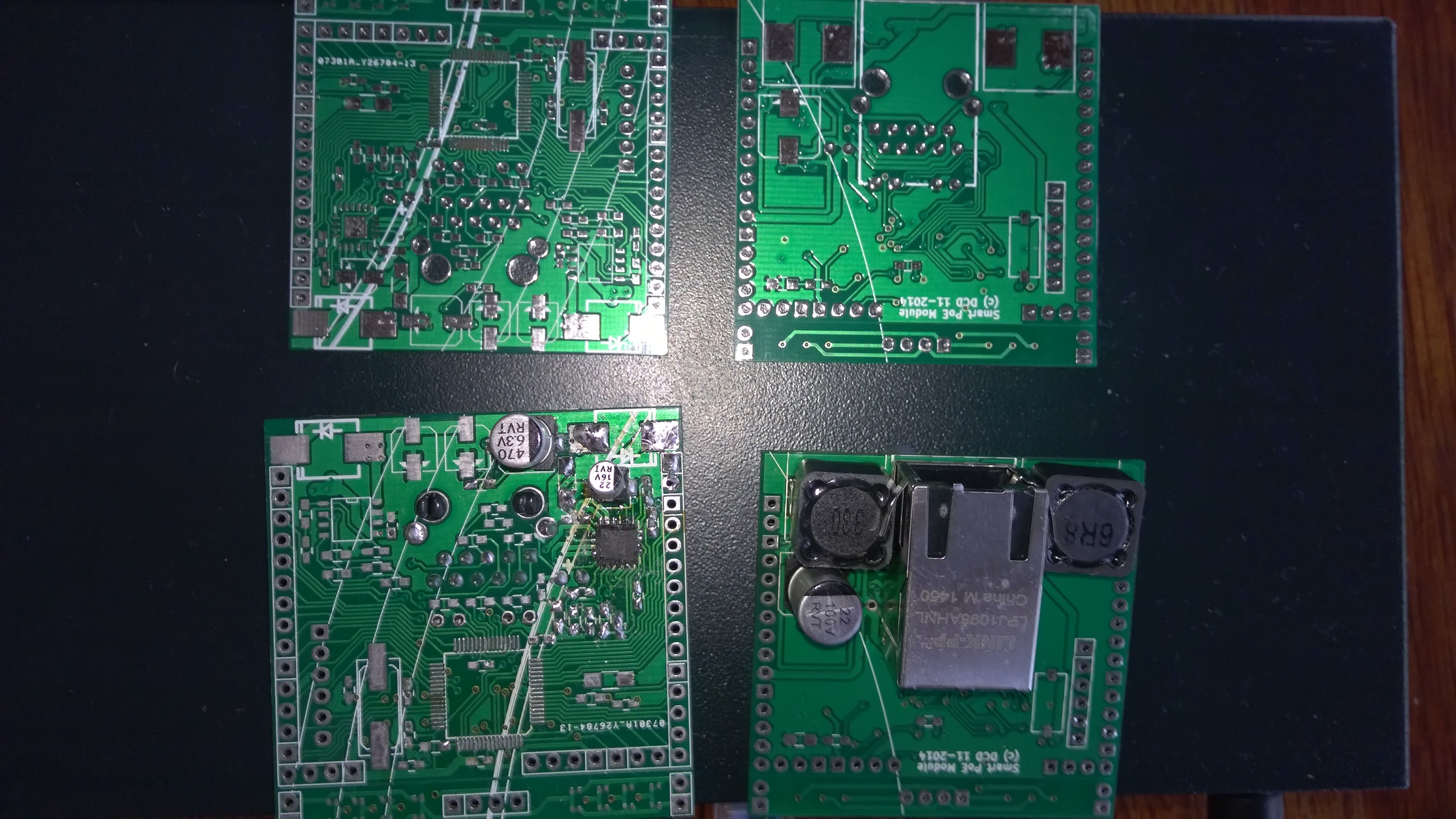
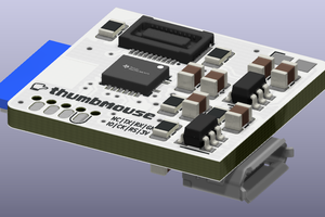
    So back to the drawing board and this time I decided to use TI's PoE solutions as I find Ti has better documentation and an active forum (better than other silicon manufacturers), and Ti have a very good range and easy to find. So giving up the fully integrated PoE chip from Silicon Labs and using the TPS23750 from TI, which is TTSOP so no mucking around with soldering QFN and PoE AF which is enough power for this sensor platform and has an integrated switcher although requires external diode bridge and MOSFET. So with some re-jigging with KICAD I got the new PoE solution on the 50x50mm PCB, and swapped for a cheaper switcher MCP1661 to boost from 3.3v to 5v or 12v to power the sensor.

    So the overall design is pretty much the same just with different chips, and this time my prototype works first time (after fiddling with the compensation circuit as the switcher was cycling on / off initially) and thanks to Ti there are a number of reference designs so I used the 3.3v 0.6a buck which is designed for IP cameras (see PMP5592 and svlrar9.pdf for the details). Also gave me the chance to redo some of the PCB layout that wasn't quite right previously (eg. all large components on the rear side of the board for better mounting - upside down).

    After a bit of rejigging some of the PIC code snippits I have posted about earlier, I have OLED, ultrasound sensor and Ethernet with MQTT communicating to my home automation server. I'll post the KICAD schematics / PCB and mplab C code to my GitHub page for those who want to have a closer look.

  • Another integrated PoE option

    deandob09/27/2015 at 07:34 0 comments

    I'm currently working on my Raspberry Pi Windows 10 IoT solution which will use a 5" IPS capacitive touch display on top of the Pi and have a peripherals board which will host a RGB24 to HDMI converter TFP401, audio amp, ambient light sensor, LED, IR receiver. But to power all that using PoE will exceed the 802.3af specs which is only good for about 5W. So I need to go to the more powerful 802.3at spec which can do up to 25w and will be enough to power the Pi and all the peripherals.

    But the Silicon Labs PoE Si3402 as a fully integrated IC can't handle that much power through it, so I have to find another solution. Most of the large semi companies aren't interested in fully integrated PoE as they can't sell you as many ICs (eg. you need 2x diode bridges, a transient suppressor, PoE logic, switcher and mosfet to make a PoE solution) however this gets expensive and makes the circuitry complex needing more PCB real estate. So I'd still prefer an integrated solution and there is a small company called Akros who sell an integrated solution very similar to the Si3402 except it needs an external MOSFET as the switching dissipation is higher, the AS1124. It is currently out of production but ample can be found on aliexpress for about $2 each and also has a reference circuit for a buck converter (which avoids having to purchase transformers which are designed specifically for PoE chips and expensive) - so suits my needs perfectly.

    I will still use the Si3402 and this design for small sensors but for the meantime I'll be concentrating on the Raspberry Pi solution.

  • Sorry about not posting progress lately

    deandob09/13/2015 at 08:21 0 comments

    I am going to redo the PCB to reduce its size and fix some of the original errors. Size reduction will mean I won't expose as many of the IO pins from the micro but as a board to host a sensor that shouldn't matter.

    I will also be making a variation of the board to power a raspberry pi instead of the microchip pic, and that board will have a class D amp as well as a couple of sensors. I have a working design from an older project (using the TPA3116 TI class D amp) that will be reused.

    In the meantime, do post any questions.

  • More progress

    deandob04/26/2015 at 02:02 0 comments

    MQTT now working. Wasn't as easy as it should have been (isn't it always....). I tried to use PIC code written for a PIC32 and porting to PIC18 but due to the complexity of all the MQTT functionality supported it proved too difficult. So I scrapped that, read the MQTT spec and implemented just the basic MQTT functions appropriate for a relatively dumb sensor (init, publish, subscribe). Wasn't too difficult but time consuming as debugging on a PIC isn't as easy as PC software and involved lots of reflashing due to fixes. I have reflashed the PIC I'm prototyping with probably over 200 times now, and no problems with flash wear (this chip is only supposed to be flashed a max of 100 times).

    The host end was easy on node.js, using the excellent MQTT components from MQTT.js on github (https://github.com/mqttjs) and easy to fit into my homebrew automation framework by submitting / consuming messages on its message bus.

    I have most of the sensor code written and working (ultrasound, OLED, GPIO, audio) so I need to finalise the code and post it up to github, then work on the basic interpreter which will need a larger memory PIC chip, so I have the PIC18F67J60 on order, I should have started with that chip for just another $1 but I wasn't expecting the microchip network library to be so fat. I also have my doubts about this library as I can see a number of malformed packets from the pic when sniffed with wireshark - it might be my implementation, but it doesn't stop the communication. I'm also thinking of redoing the board to fix the patches and making it smaller by removing some of the IO connections (current board exposes all the PIC IO pins on connectors - overkill for 99% of sensors / use cases).

  • More stuff working

    deandob03/01/2015 at 13:14 0 comments

    Just a short note to say I have the following working:

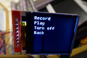
    - OLED display interface which shows a % from 0 to 99
    - Sockets server (for receiving enquires)
    - Sockets client (for sending updates)
    - DHCP and DNS lookup

    And something rather cool - Audio recorder and playback. The PIC will take line level audio input and stream it over TCP, as well as receive audio (8Khz sampling 8 bit, voice suitable) over ethernet TCP and produce a line level audio output using the PWM module.

    Next is to try the HTTP server, and use MQTT-SN.


  • Finally everything is working

    deandob01/20/2015 at 21:48 0 comments

    It took a longer and was harder than expected but I have the basics working now. Discovered a couple of faults in the schematic which translated to the board (PORTA and PORTB are the only ports that can support enough current output to light the LED on the board) and I had the Ethernet bias resistor connected to Vcc when it should have been ground. After a bit of surgery with a knife blade (10 mil tracks are delicate to alter!) the electronics are working.

    As expected, to get TCP/IP working on the chip wasn't going to be easy as the microchip TCP/IP stack library is complex and setup for their development boards. I'm also new to Microchip C and their IDE - the MPLAB IDE is quite nice, functional and easy to work with, however I'm convinced the integrated programming function is seriously broken as the PICKIT3 programmer isn't recognised but the standalone programmer works fine (lots of posts on the microchip forum about similar problems with the programmer). After about a day of hacking the library code I finally got the board to respond to ICMP pings and then to sockets calls. Didn't take long to modify my node.js home automation framework to support sockets and have the board communicating to node.js.

    Now I need to look at what type of application layer protocol to use on top of sockets. It will either be COAP or MTTQ-SN, likely to be MTTQ-SN as the pub/sub topic structure will fit into the addressing scheme I use in the home automation framework (eg. weather/temperature/outdoor) and the framework is also message driven with a broker model very similar to the MTTQ broker so I might be able to write an emulation layer to act as the MTTQ broker. Also the MTTQ client is pretty lightweight so should fit on the remaining ROM on the chip.

    Memory constraints on the chip is a concern, the TCP/IP library with sockets support takes up about 60% of the ROM and that is without a web server. I purchased the 64K ROM chip having previously managing to squeeze a lot of stuff in the older PIC chips within 2K I thought 64K will be plenty. However the lite version of the microchip compiler isn't very efficient and the TCP/IP library isn't small, so it looks like if I want to run up the web server and the tinybasic interpreter I will run out of room, so may need to switch to the 128K version. I also want to do basic audio/video for one of the applications I have earmarked for this platform, which won't be an easy task (video using the OV7670 FIFO module and audio using the PIC ADC and the PIC as a PWM DAC).

  • Updates

    deandob12/31/2014 at 23:00 0 comments


    Over the Xmas week I assembled a couple of these boards - and had a number of problems. The biggest problem was trying to solder the Silicon Labs Si3402 802.3af PD and integrated switcher. This is a cool chip as it combines the dual rectifier bridges, TVS suppressor, the PD manager and an integrated switcher with included MOSFET. All other PD solutions required a lot of extra components which adds to the expense and board real estate. 2 problems with this chip, the QFN profile is a real pain to hand solder and I had literally 10 attempts to try to get it right, with a combination of hand soldering, using a sandwich toaster (heater on top and bottom) as well as a makeshift hot air gun using a paint stripper gun with alfoil on the nozzle to direct the hot air to the chip. All these methods worked to some degree, and I learnt how to time the solder melt to emulate wave soldering but the biggest problem was getting the chip aligned as it was so small. The pads on the board I used should have been a little bigger to make the soldering easier, and I finally got it working with a combination of hot air soldering and hand soldering afterwards. This particular QFN did not have much metal exposed on the side of the chip so hand soldering was really tough, so pre-tinning both the chip and the board was needed, and using a small screwdriver to force the chip down onto the board to make good joins on all pins when using hot air soldering was needed, and amount of pre-tinning had to not too little (won't make a joint) or too much (creating a bridge on the underside of the chip). Solder paste would have been easier.... So when these boards were fired up and didn't work I wasn't sure it was the soldering, the board or the design. Unlikely to be the design as I pretty much kept to the data sheet and application note, and validated it against a 3rd party schematic for a similar design (Olimex PoE board). I triple checked my schematic in Kicad and the board and apart from a couple of small changes that should not have mattered I was sure everything was OK. When the board powered up, it performed the 802.3 classification, started up the switcher but then the switcher shut down and cycled through the startup sequence again. Not being able to see the quality of the soldering under the QFN chip I pretty much blamed the soldering for the problem so re-did the chip many times (the hot air gun was perfect for desoldering). By the 10th try I thought I'd re-read the data sheet / app note to see if I was missing anything, re-checked the component values etc. and found a short sentence in the middle of the datasheet that said in some situations the switcher will cycle if there is a small load present. I had actually used a small dummy load (100 ohms resistor on the output) as the Olimex design had this, however it wasn't enough especially as I hadn't soldered the PIC yet (wanting to see that the PoE output voltages were OK first) and when I dropped this to 50, voila the board fired up and stable. I had spent literally a couple of days on this and getting quite frustrated so was pretty happy to see it working, and validating that the design and board were OK! If that last change didn't work I was about to redo the boards with another PD chip.

    The second problem for me was that due to restricted board space I was using the non-isolated design so the output earth was referenced to 48v - 3.3v and once I had the PIC soldered up I fired up for the first time the PICkit 3 programmer and plugged it into my PC, then into the programming header on the board. The PICkit has a translucent case and I could literally see fireworks inside the case and the familiar smell of burning silicon. Both the PIC and the programmer were toast - this time I knew exactly what the problem was, as I had problems with my USB oscilloscope earlier when trying to debug the PD chip for the same reason. In use it won't be a problem as the sensors will only be connected to Ethernet, but as the...

    Read more »

  • Easy IoT Ethernet Sensor

    deandob11/16/2014 at 11:27 0 comments

    Design finished

    Schematics finished

    PCB finished (using iteadstudio - $9.90 for 10x PCBs!) awaiting arrival

    Components ordered. Awaiting arrival

    JavaScript TinyBasic console prototype finished

    PIC code not started.

View all 8 project logs

Enjoy this project?

Share

Discussions

Similar Projects

Does this project spark your interest?

Become a member to follow this project and never miss any updates