The Arduino library can be downloaded from the github page here:
https://github.com/yspyG/AVR-Battery-Monitor
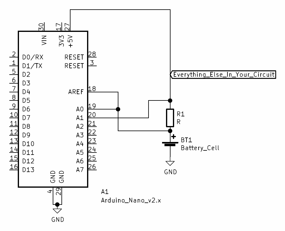
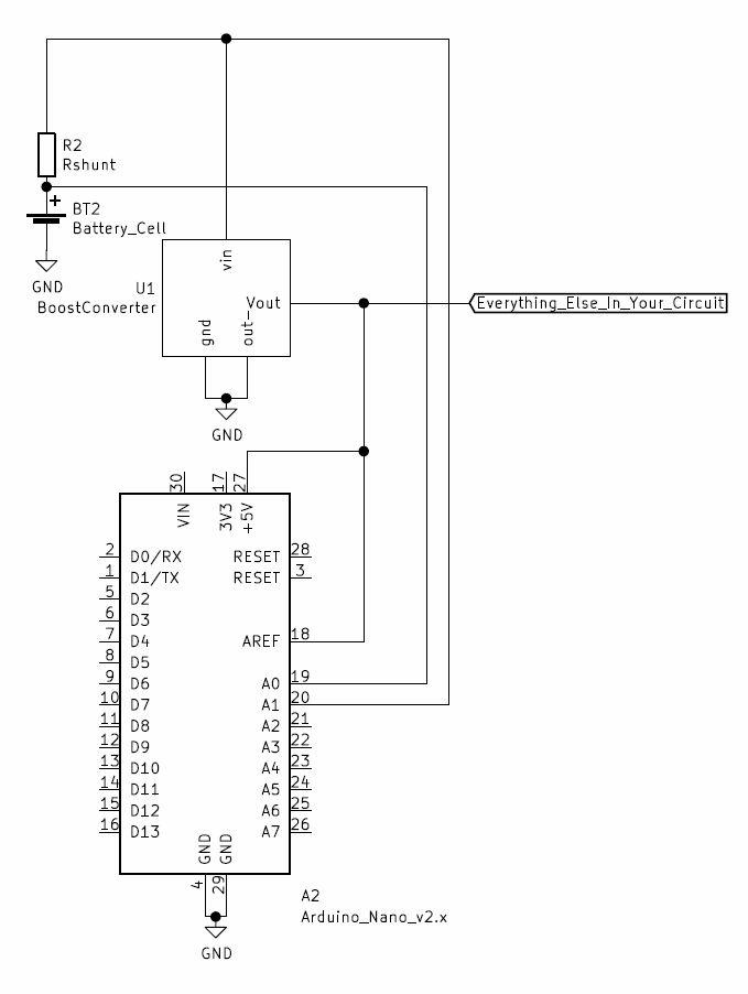
This project utilizes the ATmega328's internal 1.1V bandgap reference to allow for accurate measurements of external voltages. From these measurements the library is able to measure the external voltage, allowing users to choose what to do in undervoltage/overvoltage/overcurrent cases within their projects. External components are kept to an absolute minimum, requiring only the battery and a shunt resistor (which isn't needed if you don't care about current draw). It is worth noting that as the project stands right now for Arduino boards there is no way to prevent current from the USB programmer from going into the battery and causing problems. As a result, be sure to have the battery disconnected whenever programming. See the github page for some simple circuit guidelines for this library. This library is also capable of monitoring the battery while the Arduino is powered by a boost converter for those who need 5V instead of whatever the battery happens to be at.
For anyone curious about what's happening behind the scenes the battery voltage is calculated by:
where A terms represent the ADC value returned by reading the pin.
The current is found using the equation:
For anyone interested the full derivations are available in the logs of this project.
This project is still ongoing, and awaiting parts for thorough testing.
 Matthew James Bellafaire


 Sagar 001
 George
 ROFLhoff
Make sure the voltage across the shunt resistor will not exceed 0.5V or the voltage at A1 will exceed the maximum voltage of Vcc+0.5V.
You could add a high value resistor between the battery and A1. Then if the voltage drop acros the shunt gets to high, the clamping diodes of the A1 pin will keep the voltage at A1 in the safe range. The resistor will prevent to much current going through the clamping diodes.
Otherwise (most of) the current will bypass the shunt resistor and go though the clamping diode. I've actually done that a few times, not realizing that Vcc wasn't actually attached, and the whole project was powered from the ISP pins (MOSI, SCK), though the clamping diodes. So I found out the are quite robust little diodes (-;