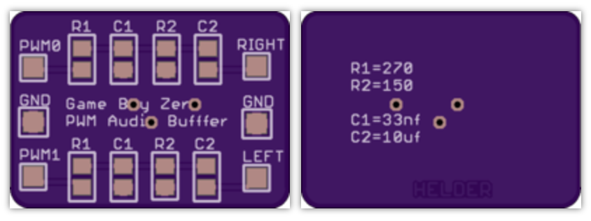
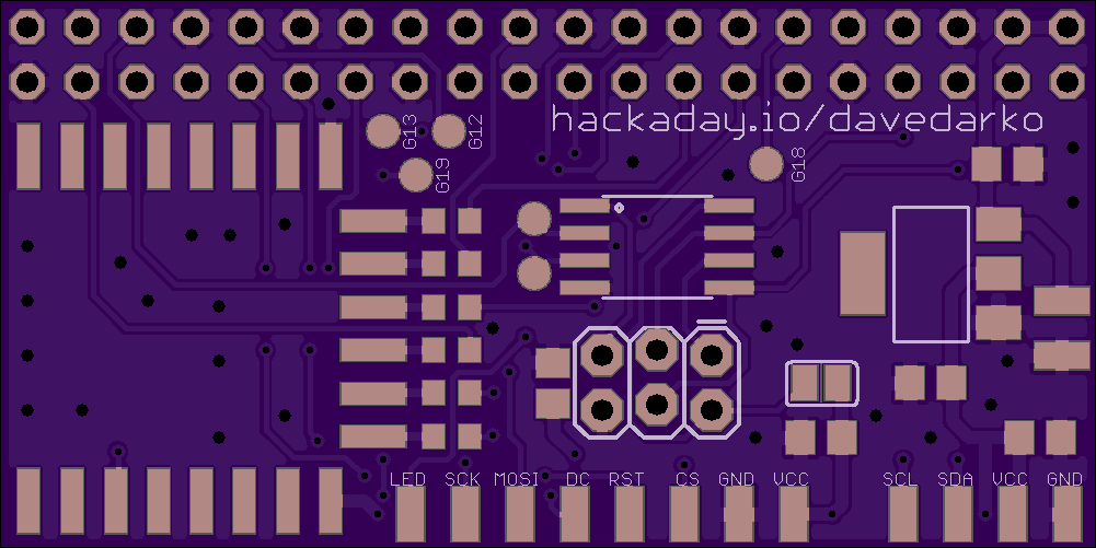
There is currently no sound on this board, but I've ordered this anyway with some testpoints for the possible sound pins and an extra board you can check out below (not designed by me but someone who builds raspberry pi portables). The attiny85 is connected to the PI via I2C and the TFT LED output of the driver - think basic on/off via driver and pwm via i2c. It's a decent prototyping board to get along, I think.
Gameboy Zero PWM Audio SMD - by Helder
https://oshpark.com/shared_projects/qUEOjE0n

 davedarko
Discussions
Become a Hackaday.io Member
Create an account to leave a comment. Already have an account? Log In.
Nice layout!
Are you sure? yes | no
Thanks :) of course it is based on your wifi board, but the edge connectors should really help me with the cable management.
The board I'm most proud of atm is the one over here though: https://hackaday.io/project/16188-game-boy-catridge-plus-programmer/log/49455-boards-ordered
Are you sure? yes | no