smartroad
-
Major Upgrade
12/11/2020 at 11:24 • 0 commentsI have been working on a major upgrade for the amplifier. I wanted to move away from using pre-made amplifier boards and have created a new 70x70W amplifier board. This is using a Class-D amplifier chip capable of two 70W outputs. I wanted more power as the speakers I have are about 80W so using my current setup I have to drive the amplifier quite hard. My design still uses the same pinout as the Adafruit unit for the control and audio inputs, mostly as I envisaged it as an upgrade rather than a full re-design. Hopefully, if this works, I want to design a few different power level amps to go with this, making it more modular.
This new design will have 7 inputs (using a built in version of my Audio Input Expander) and I am upgrading the display to use a full 128x64 graphic display. The Arduino Nano board is out and a custom ATMega644 controller is going to be used instead. This allows for more memory for the display and, hopefully, a nicer more modern look to the amp.
I have the boards for the new amplifier which I hope to get made over the next few weeks. Although I made one big mistake in that I somehow deleted the digital potentiometer footprint and will have to get them remade in the future. For now I can check my design will even work for the amplifier chip, the digital pot is not needed for initial testing.
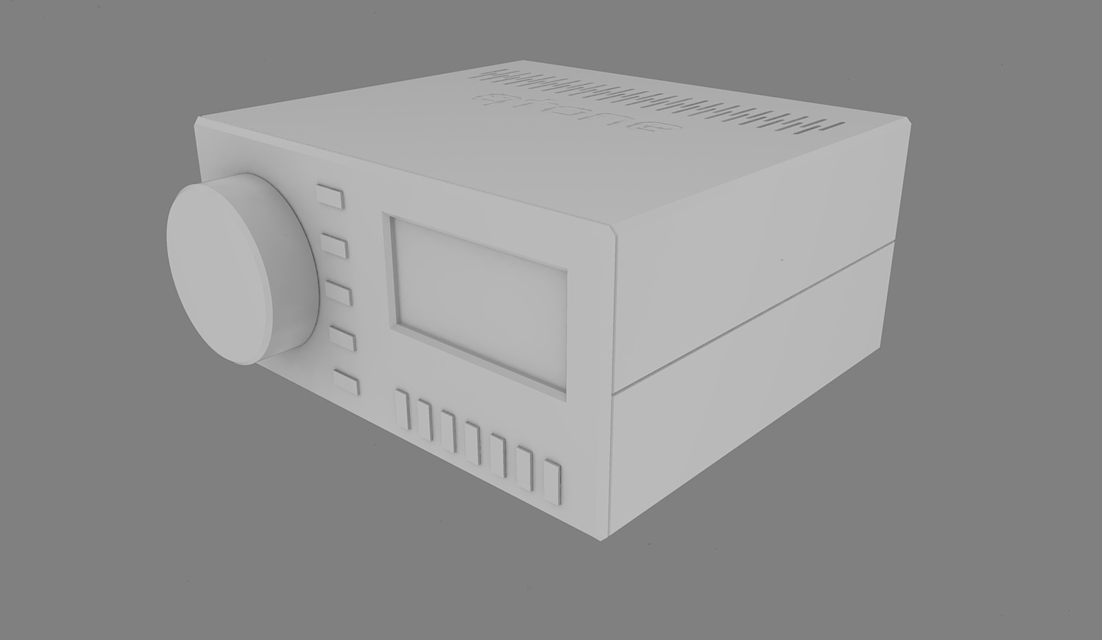
The case is also getting a full redesign with a more streamlined look. I made a simple amplifier for my retro-computers to use, couple of cheap amp boards from ebay, and I made a case that is much easier to construct than the original one, with fewer screws holding it together.
![]()
About the only thing I am having problems with is powering the new amp board. It needs 36V and there aren't many PSU's capable of the power output needed so I may have to look into designing one. Hate the thought of dealing with household voltage levels though!
-
A Mute Solution
06/21/2020 at 08:47 • 0 commentsIn my last log entry I mentioned about the need to mute the amplifier while the unit switched on as you need to give the amp chip about 1/4 second to boot. This meant that the amp would play anything on the input at near full volume until the controller could turn the volume down. The controller doesn't have any IO left to control the mute pin on the amplifier so I needed another way to hold the mute pin low for at least 1/4 second.
I wanted it to be as simple as possible so started with the idea of a simple RC timer to hold the pin low. While this worked, the issue came from the inability to quickly discharge the capacitor once power was removed. This would have meant that if the power was applied before the capacitor has discharged it would start again at full volume. The capacitor does discharge, just painfully slowly!
After a lot of investigation I came to the conclusion that I would have to go a bit more complicated. On that post user Ken Yap said about using a small basic microcontroller to hold the pin low, but that felt a bit of a misuse of a microcontroller, although I did appreciate the suggestion :D
That though made me think, there is a chip that is A) Cheap and B) designed for this exact purpose. The venerable 555 timer!
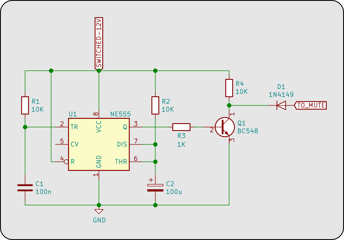
![]()
The above circuit diagram shows the 555 in astable mode. Just for anyone who doesn't know about the 555, astable mode means the 555 will start with pin 3 (Q) output high and after a specific time with go low and stay there until power is reset. R1 and C1 provide a brief pulse to trigger the timer when power is applied. R2 and C2 are the main timer, providing about 1 second of delay. The transistor is used to invert the output so the junction of R4 and the collector of the transistor is low when Q is high and vice versa. The diode is used to block the high voltage so the "mute" pin is only pulled low as there is a resistor on the Adafruit board pulling it high and I didn't want to risk injecting 12V onto the 3V rail! -
Help Requested! - Mute on Startup
06/19/2020 at 11:40 • 5 commentsFor some time I have been aware of an annoying "bug" that I can not seem to squash. When the amp powers up and audio is playing you get a brief, about 1/4 second, blast at nearly full volume. This is due to the MAX amplifier chip starting at a reasonably high volume when it is first switched on. The chip does have a mute pin, which the Adafruit breakout board I am using does, well, breakout. I would love to use it but unfortunately I don't have any spare pins left from the Arduino Nano.
So I got to thinking, could I use a capacitor to hold the pin low while the amplifier started up. I ran some quick experiments and yes I can, with a big caveat: I can't figure out how to get the capacitor to discharge quickly when power is removed.
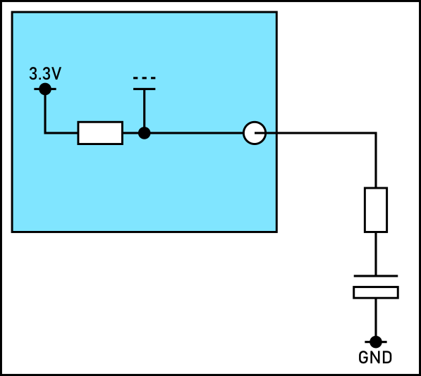
Here is a basic view of the circuit idea. The amp has the mute pin held high with a 10K resistor connected to the gate of a MOSFET that then connects to the mute pin on the amp chip (I haven't shown that part of the circuit). On the right is the simple RC timer I was thinking of using.
![]()
The values I thought about were 100uF for the capacitor and about 330R for the resistor. As it stands the capacitor doesn't discharge at all quickly, but any resistor I put in across it causes a potential divider to change the voltage at the gate of the MOSFET. I was hoping someone might be able to help point me in the right direction on this, or even if it is possible!
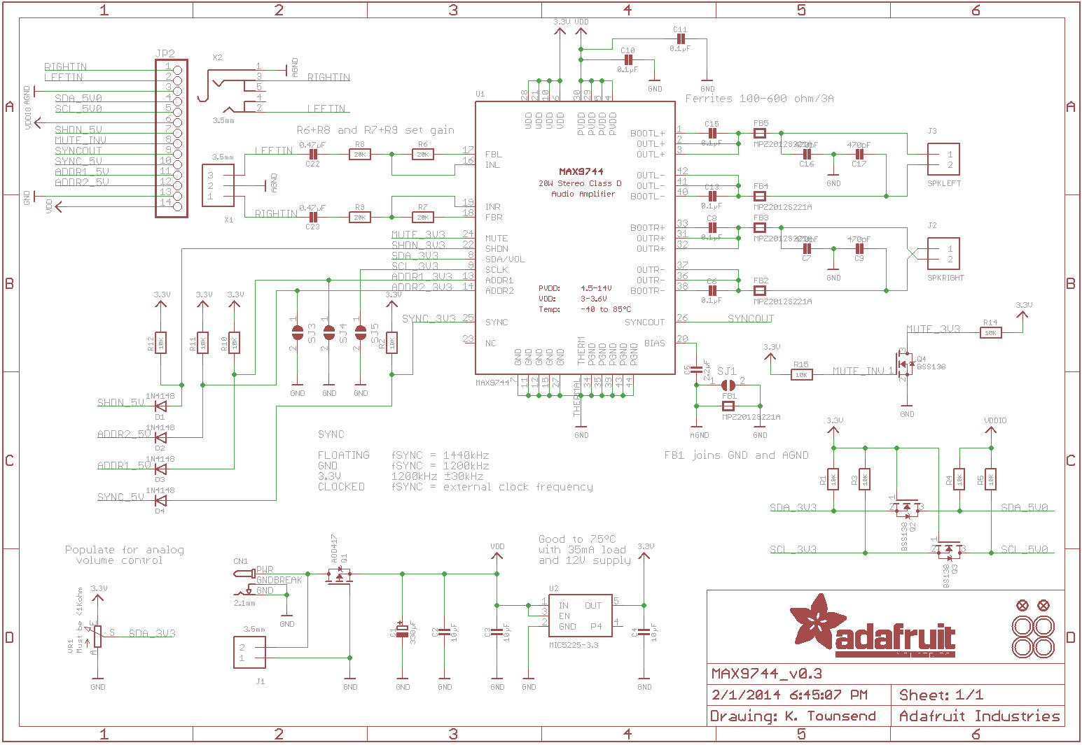
The full circuit for the Adafruit breakout board is here, the part of the circuit is in B5-C6
![]()
-
IR Working!!!
05/20/2020 at 16:33 • 0 commentsI finally got the IR code working in V1.4!! I now have the ability to control the amplifiers essential features from a distance. With the remote you can control the following features:
- Power
- Volume
- Mute
- Treble/Mid Range/Bass levels
- Inputs
The volume control will also increase if the button is held, something that took more head scratching, curse words and childish temper-tantrums then I would like to admit... Essentially the problem was that every time I tried to implement the auto repeat so the volume would increase as the button is held would result in it increasing by an extra one step on release, including if you only tapped the button.
Finally I found a way to stop the behaviour and it works as expected. There is a half second delay after pressing the button so that it doesn't repeat if you just tap on the button. The timer is reset every time you press the button so you can tap the button to increase or decrease the volume one step at a time.
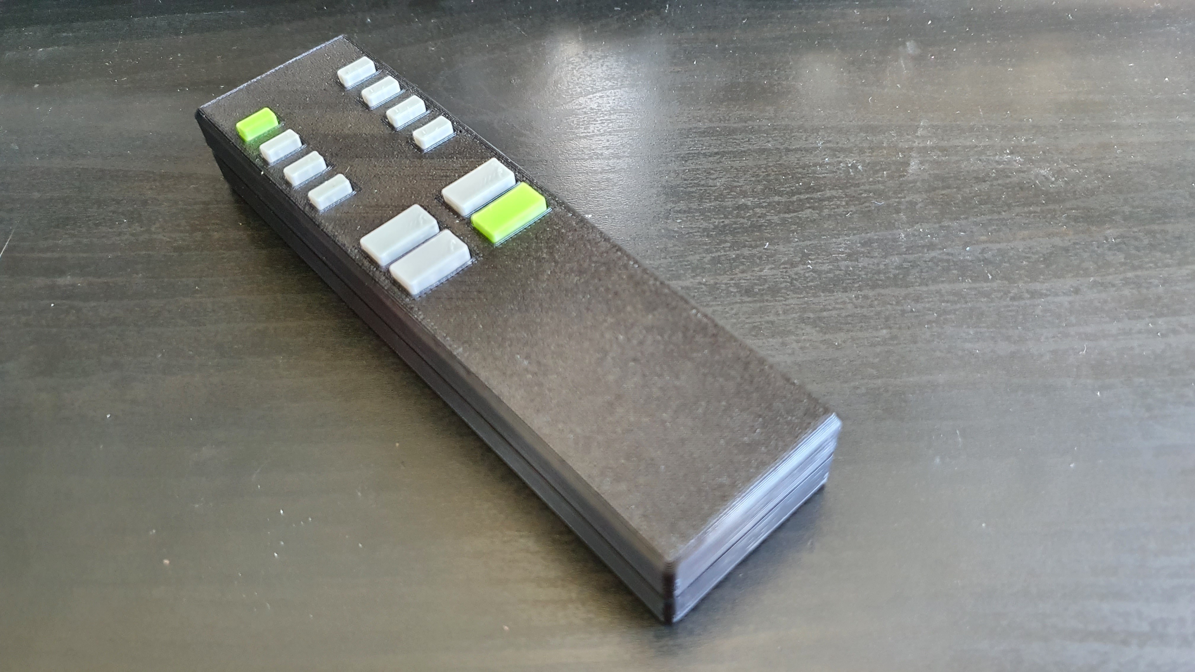
I also printed off a remote control using my universal remote design, which I will include the code and case design files for as well. As I have the ability to do multi-filament I coloured the power and input four buttons the same as the amplifier.
![]()
-
IR Remote and Artwork Finalised
05/15/2020 at 08:36 • 0 commentsSomething thing that I have been wanting to add to the amplifier is a convenience option present on all modern technology, the IR remote. The main thing that has stopped me from implementing it has been the trouble getting a remote that would work for the functions the amp has. Custom ones are expensive and generic ones are, well, generic. One of my other projects has been to make a remote control using an Arduino to replace the missing remote for an "old" Sony tape deck and CD player. Now that I have that working I plan to use it to make a remote for my Amplifier.
The controller PCB does have a space for an IR receiver but it wasn't used on the early versions, as such I needed to reprint the front of the amp to have the hole for it to fit into. This also meant updating the graphics for the sticker on the front.
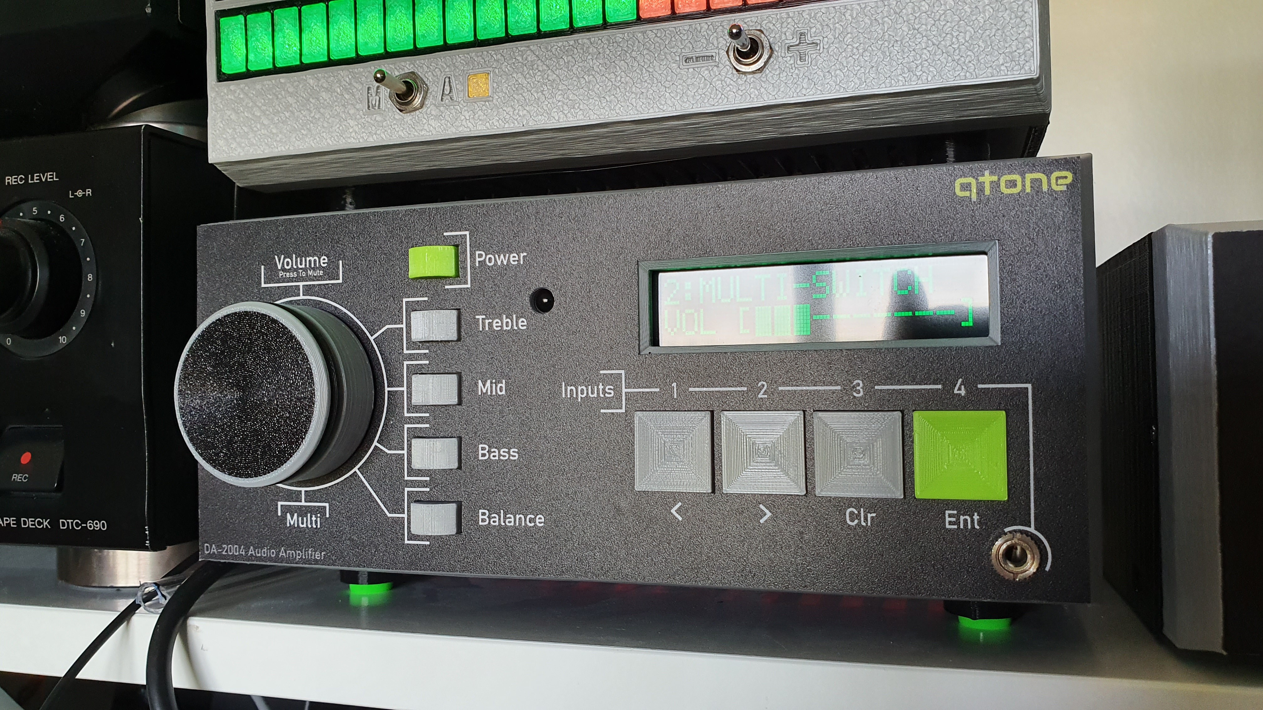
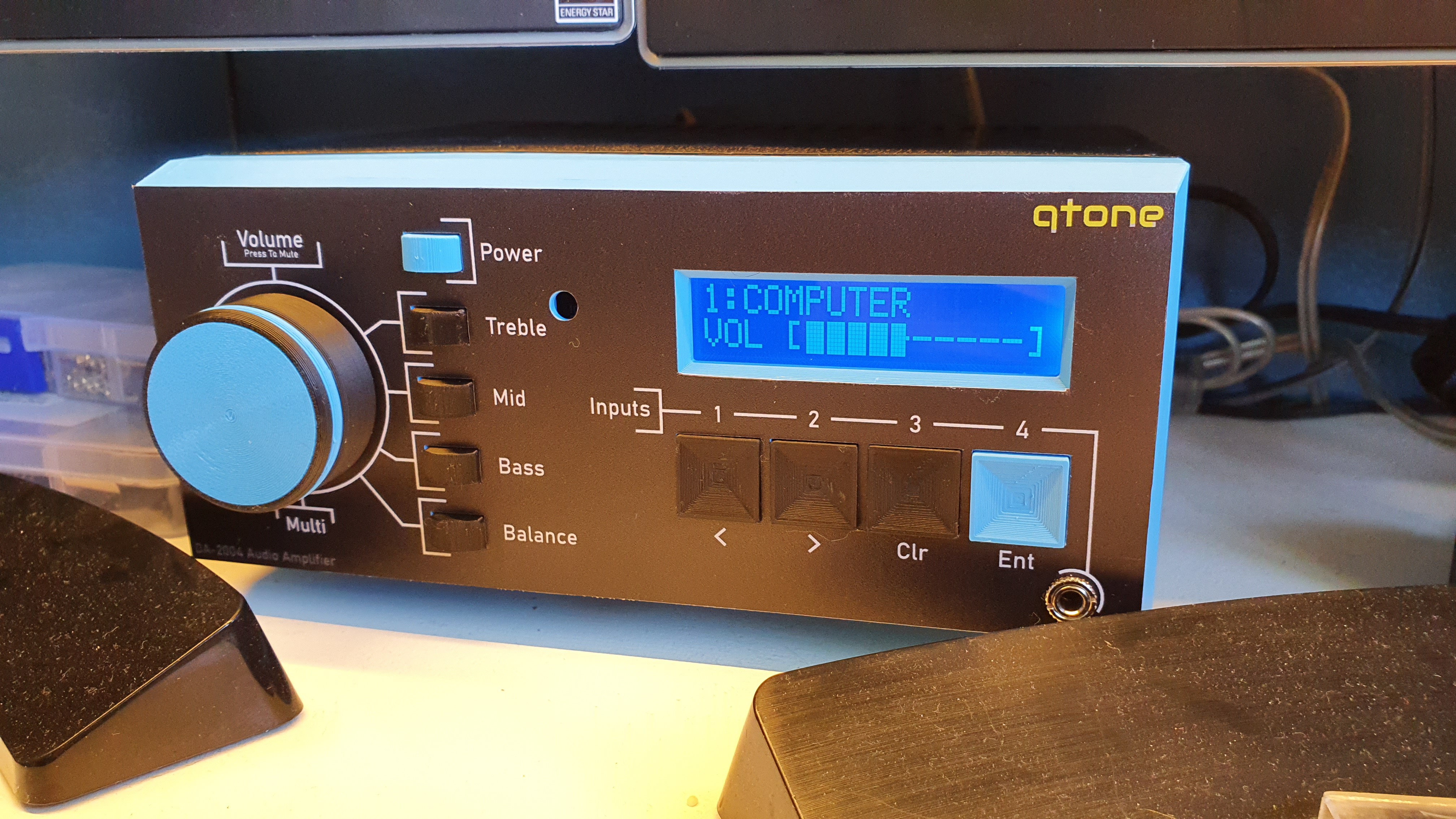
![]()
![]()
Above are the two versions I have printed (the LCD on the lower photo has the RGB backlight). The top one, grey buttons and panel, has the IR receiver, the lower one doesn't as it is on my desk so didn't see the need (yet!). The artwork was updated to have the cut-out for the IR receiver, the font has been improved to a clearer version and some of the formatting was fixed. The company I used to make these vinyl stickers has changed the material from the first versions I had made and this new one looks so much better (and seems to be better at not showing fingerprints!)
I am working on the new firmware to control the amp via IR remote so hopefully will be able to release that (and the design files for the remote itself) soon. I'll upload the new sticker files to here soon.
-
Firmware Update 1.3.2
02/09/2020 at 18:54 • 0 commentsYesterday I uploaded a new firmware version to add a feature that corrects a bug. The bug was clipping audio from certain devices. Initially I thought is was to do with the 4 to 1 audio expander I have been making (see my other project) as the only devices affected were the ones that were plugged into it. It took a while but after some investigation it wasn't the expander at all! Turns out it is the way I have the volume controls organised.
I run both my amps using the Adafruit Digital amp board. This board is able to control it's own volume via the I2C bus and that is how the volume is controlled when it is detected on boot. The input and tone selector chip on my board also has a volume control, but this isn't used in this case and is set to -5dB because originally I set that level to reduce the clipping that was happening.
Problem came about because that was done before I had the additional kit that was causing the clipping. After I finally figured it all out, I updated the setup menu to be able to adjust that volume by the user, allowing easy adjustment to prevent clipping.
This is a bit of a bodge at the moment because it doesn't care about the type of amp connected currently, something I ran out of time to implement before I had to leave for work.
Hopefully I can get that sorted so it will prevent that option being available if the Adafruit board is not connected!
-
V1.3.1 Released
01/14/2020 at 22:00 • 0 commentsThis version update can now detect the type of amplifier attached to it, currently the MAX9744 or none. Which amplifier it has found is shown in the settings menu and will show "MAX9744" or "Custom". The detection is done on hard power up, i.e. when power is applied/attached.
With the custom option (no MAX9744 board attached) then any amplifier can be attached to the VU output RCA connectors or internally using the RIN, LIN and AGND pins on the MAX9744 connector. With the MAX9744 connected the volume control is controlled by the MAX chip. When it isn't detected then the TDA7439 chip will control the volume.
The advantage of having the MAX chip control the volume is so that the VU output remains at a high output level regardless of the amplifier volume setting. Making it ideal to connect a visualiser to as it will always show the signal that is being fed into the amp.
Eventually I plan to make a daughter board that will connect to the MAX connector and allow it to maintain the VU output functionality while still providing a custom amplifier option. Mostly the thinking is that this allows connection of a more powerful amplifier if you need it.
Bug Fix
In 1.2 the settings menu would sometime keep the last square bracket from the saturation setting when using the RGB display.
-
Firmware Update V1.2.2
09/25/2019 at 08:26 • 0 commentsNow that I have the RGB backpack for the RGB backlight LCD I have updated the firmware to take advantage of it.
This new firmware will auto detect if the RGB backpack is connected and if it is detected it will allow additional options in the new Setup menu. This menu (reached by holding the power button down for two seconds) opens to show the current firmware version installed. The multi-control is then used to navigate the other options. If the RGB backpack is detected it will allow you to change the colour of the backlight (16 options, all with amazing names...), the brightness and the saturation level. Technically this allows for about 400 different colours and shades, although in practise there are many that will look very similar! I am considering using a gamma correction for the brightness and saturation as it is linear now which doesn't always look best on our eyes.
The backlight can be set to dim/turn off after a period of not being used, options from 1 minute to 30 minutes. If the RGB LCD is used then it will dim the display to 50% of the current brightness settings. Should the LCD be a standard single colour, the backlight will be turned off.
In the next update I am looking to add the ability to not need the Adafruit amplifier so you can use it or any other amplifier you want should you want more power. To maintain the full feature set I am currently designing a board that will sit between the controller and amp (where the Adafruit amp is connected) to provide the volume control before the amplifier. However the system will be able to run without it, by using the volume control of the TDA7439DS chip, but the VU Meter output would scale with volume rendering it useless. Hopefully I will be able to implement an automatic detection system, like I have for the RGB backlight, so that it doesn't matter which option you want, it should just work out the best way to operate.
-
Updated files
08/19/2019 at 16:01 • 0 commentsI have split out the files into separate zip's, saves downloading one file just to get the Arduino code (for example). I haven't included gerber files, mostly because they can easily be generated, however would they be useful?
The electronics zip file now has the 3 circuits to be able to build the amplifier. My next thing is to write a BOM for easier ordering as the circuit diagrams don't show the additional parts needed (RCA connectors, rotary switch etc).
-
Initial Upload - Changing to KiCad
08/18/2019 at 15:59 • 0 commentsThis is the initial upload of all the files for making the amplifier. I recently made the transition from Eagle (which I made the prototypes on) to KiCad so currently the only circuit and PCB available is the main IO and tone board. Over the next week or so I will add in the circuits and PCBs for the Arduino controller and the input buttons. Please be aware: at the current time I have not had these KiCad version made so while they should work there may well be error's creeping in.
I think I have included everything in the zip file. There are the 3D files for printing. I have included the STL files and some UNTESTED 3MF files for my new Prusa MK3S. The photos you see in the main listing are from my old printer. This is a long print but I think it looks great. Also included are 2 SVG files for the front and rear panels. I had these printed on vinyl (the green lcd picture) and I think they look great, although the blue lcd shows it printed on sticky paper which works just as well. For the feet I used 12x5mm rubber feet.
The Arduino program in included as well, there are several support libraries needed to go along with the main program. I wrote a small manual on using the amp, assuming that you use the same case as I have of course! At the back it lists the libraries that are needed (I think they are all installable from the Arduino library manager).
I hope to maybe sell these as a kit, would that be of interest to anyone? The main chip is the only SMT part, it is easy to solder with some extra flux but I would offer to solder it first for the kit.
Please have a look, I welcome any constructive feedback!
Customizable 20W Amplifier
4 Input, 3 Way Tone Control and Customizable LCD Display