rrace001
-
New Board Design
09/06/2019 at 20:50 • 0 comments![]() .
.![]()
I removed the USB because I cannot fit the code on the board with the Arduino Bootloader. I am going bare metal on this to save about 7k of room. This gave me two more pins to use.
I used one to add another line to the tri-state multiplexed LEDs which increased the LEDs from 20 to 30. I added 8 to the strobe which increased it from 8 to 16 and put them in a straight line for better viewing. I rearranged the LEDs from a 7 segment to a dot matrix type arrangement. Should look a little better. One LED was left from this so I put it on the top right corner of the dot matrix for a sharp indicator.
I used the other pin with a transistor to switch the ground on the opamp. This so when it shuts down it does not draw any current. The last version had drawn about 2 mA which is too much for standby.
I also added room for a AAA. I am hoping to just use a CR2032 so I have footprints for both. I am not sure I can get the full performance amp draw down to 3 mA so the AAA will have no problem if needed. This required adding a 3v3 booster and inductor. Since I took out the usb then I did not need the regulator.
I have never done baremetal on a SAMD but found an excellent github repository for SAMD processors called mcu-starter projects. This is very minimalistic and is serving as a great starter for SAMD baremetal. It has Atmel Studio files but I have never used them. There is a make file for generating binaries using GCC. The binary files produced from this are very compact. The author also made a very unique hardware abstraction layer file which is blazing fast. I had clocked the io pins using this and it seems it is no different then directly manipulating the registers using CMSIS. CMSIS (Cortex Microcontroller Software Interface Standard) files are in the repository and are a slight version different from what Arduino uses but no problem. I am so glad I found this because it has only a few files which I am not familiar and that is the linker and startup files. No need to edit but should great to learn from. The only bit of learning I needed to do to switch from my Arduino sketches was that I had to figure out to get the clocks up and running. Only the default is setup in the repository but after going through the Arduino startup file then I was able to get the clocks up and running for the timers. So far so good.
I got a couple weeks while waiting on the new boards so I am hoping to have all of my code in the baremetal version up and running before they get back. Already thinking about a SAMD 21 tuner so I can use the Arduino bootloader and maybe Circuitpython. I had built a POV fidget spinner with Circuitpython and it worked great. Only thing is I could not figure out how to access the registers. Not sure if Circuitpython supports this or if there is a way to compile a different version using CMSIS but that is well over my head at this moment. I believe Micropython has the ability to manipulate the registers but that is on STM. Not sure which rabbit hole to head down...
-
Added Feedback Capacitor
08/25/2019 at 21:01 • 0 comments![]()
Added a feedback capacitor on the first stage of the amplifier. I was having a problem with a superimposed wave on top of the high E on the guitars. Before I started this project, I made a feather wing to test out the 12mm piezo discs I used on this tuner. I did not add the filter caps on the feedback paths of the amplifier to see what would happen and it worked well so I did not include them on this project. This might be due to the LM324 frequency response being very low which is why i tried it out. No sense in filtering something out the amplifier will not amplify if that is the case. When I had seen the superimposed tone, shown on a previous post, I assumed it was due to the feeback capacitors missing. I struck the string many different ways to see if it was an overtone and could not get it to go away. I just added the capacitor and it dimished it a little but I believe this is not the problem anymore. I am able to strike the string with my fingernail and the tone is clean. Snapshot above. I strike it with a pick and the overtone returns but a little diminished. Never had seen this before but I am new to piezos. The electrets and mems microphones I used before never shown this overtone. Not sure I understand how the piezo picks it up but not a microphone considering it is a high frequency - about 2k. Anyway, I want to stay with the piezo because you can use them in noisy environments. Could add an electret with a switch but maybe on a different version of this project. So far all is working out in principle.
-
Strobe Test
08/24/2019 at 00:09 • 0 commentsThe strobe code works very well but using only 8 LEDs for the strobe configured in a circle does not work well. All of the LED strobes I have made before were in a line because I used perfboard and they used 16 or more LEDs. Having 8 LEDs in a circle makes the strobe hard to see because of the noise which makes it look like it is random. You can still tune a guitar but it is takes a lot longer. This was never a problem before because when they are in a line the mass of on LEDs was very distinguishable. To make sure the code was good I had modified it a little to output the detected signal and hooked it up to an external strobe and it worked just as always. Using only 8 LEDs did not look nearly as good as 16 LEDs so I am going to change the strobe to 16 LEDs for the next iteration. Having 16 LEDs makes the signal very clear and very easy and quick to tune. Problem now is that I need an extra pin for the extra 8 LEDs. Looks like I will need to go to the 20 pin version of the SAM D11. That is probably the right thing to do because I am sharing two LED pins with the programmer right now. Not that it does not work but probably not supported by the manufacturer. So now I am on the straight and narrow. And so will the LEDs because I want the next iteration to be the one I send out for others to try out and so no untested configurations - as much as possible. I uploaded the test code to github.
-
First Tests
08/23/2019 at 00:08 • 0 comments![]()
![]()
![]()
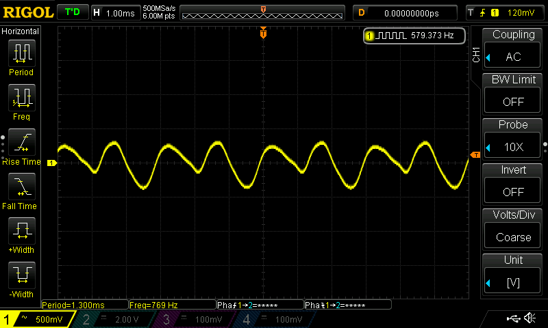
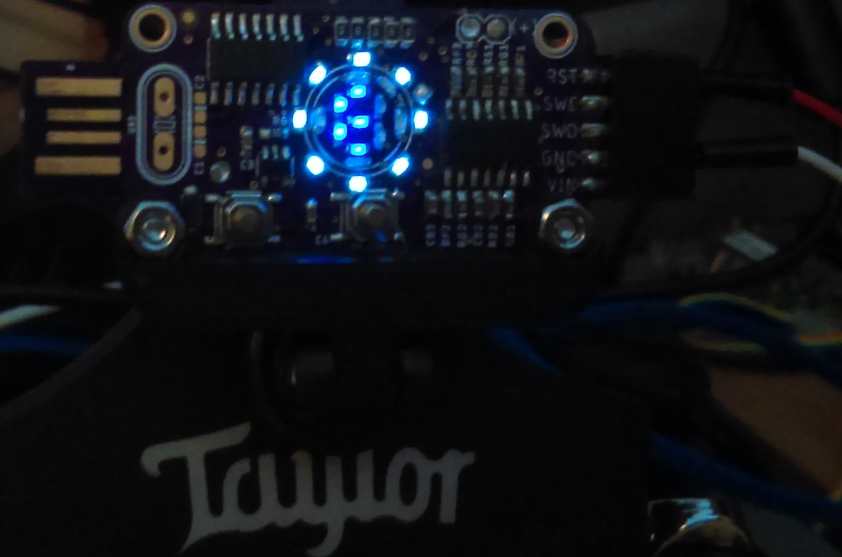
The different color LEDs have a drastic difference in brightness. The photo is terrible because I turned off the flash for the LEDs to be visible but it does not show the brightness difference due to this. The outer ring is made up of diffused white 0603s and the 7 segment is made up of clear blue 0603s. The white is very bright and the blue is not so bright. I like the diffused so the next iteration will have diffused all around and I will try to better match the LED brightness. Overall the circuit is drawing to much current which was somewhat anticipated. I have a couple ways to deal with this so I might be able to keep the 2032. If not then either go with a AAA with a booster or a lipo. The opamp works best when being powered by a battery but I want the AAA and that needs the booster. Could go with two 2032 but not sure. Hard decision...
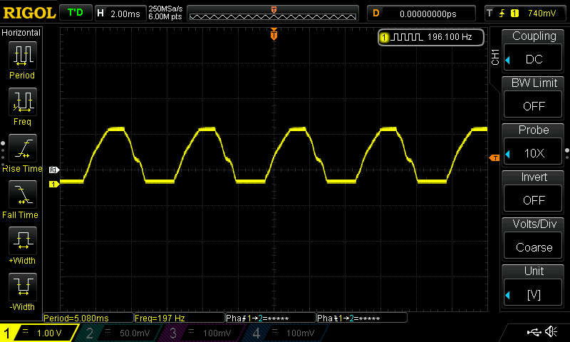
The middle scope snapshot is the g string and it is clipping because there is only about a volt and a quarter head room do to the LM324 1.5 volt limit within the positive rail. This is anticipated as the voltage divider is 1/4 VCC. The clipping on the top and bottom is about even so that turned out good. I zoomed in another step for the E string, bottom, and struck it a little lighter. This has me worried because of the noise on top of it. Could not get rid of it by striking the string different or muting the others. Not sure if that is a harmonic or some type of ringing. I left out the filter capacitors on the feedback paths of the opamp to save some room but now I am thinking I should not have done that. I am going to try and piggy back the first feedback resistor with a cap to see if it reduces this noise - if that is what it is. I have never seen that before so a little confused. I might also try swapping out the LM324 with a LMV324 for the rail to rail and possible cleaner feedback. My other projects never had it so I need to do some probing....
-
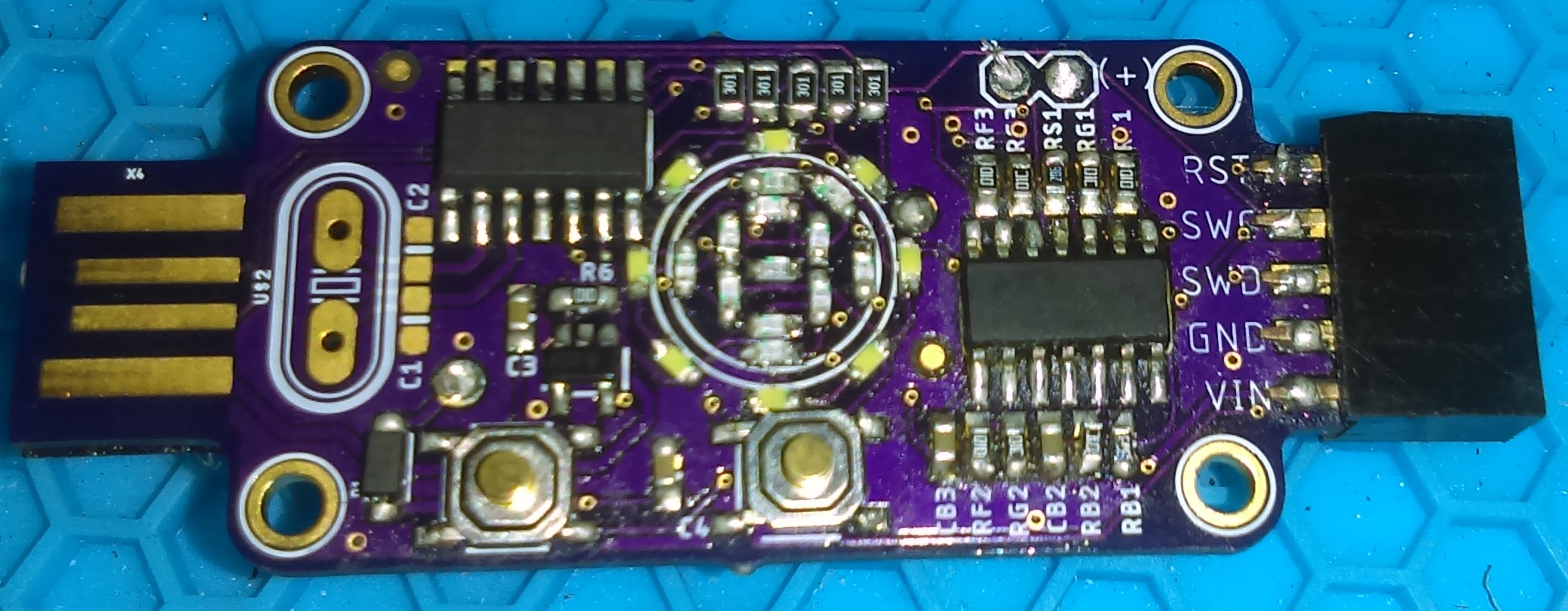
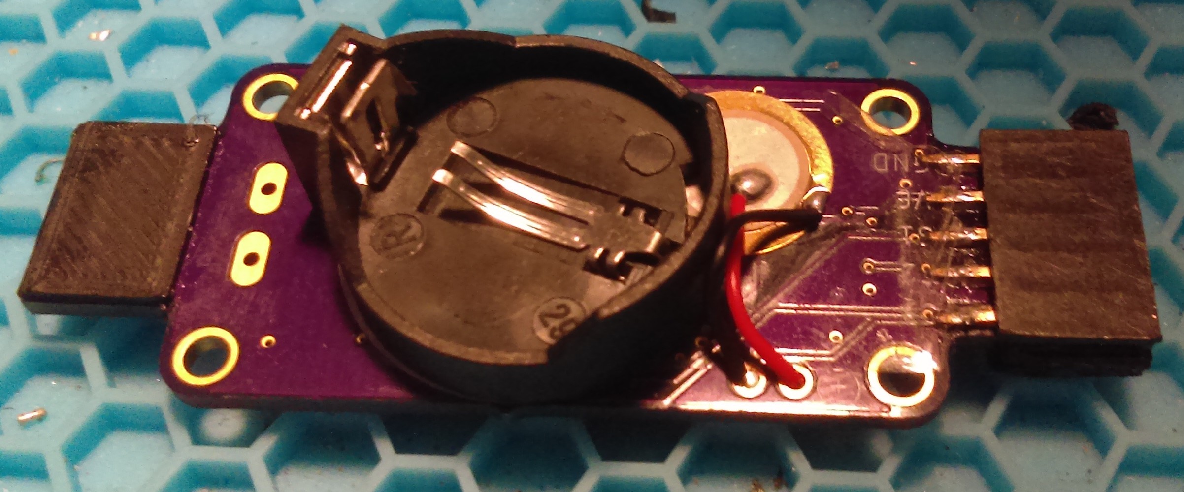
PCB Populated
08/21/2019 at 21:58 • 0 comments![]()
![]()
Populated the PCB using a solder iron opposed to paste. This is why I had chosen the larger packages though you can still hand solder the smaller ones but they are difficult. The best video on hand soldering I have seen was by Ladyada from Adafruit. Her videos are the reason I got into surface mount. Looks so intimidating until you do it.
OSHPARK PCBs only come in two thicknesses and they are not thick enough for a USB slot. I glued a spacer on it to make it fit. I have used Elecrow before and they are almost as good as OSHPARK and a lot cheaper but takes twice as long to deliver. For small PCBs, OSHPARK is the way to go. The piezo is partially under the battery holder. I think it will be OK but probably not good for manufacturing. I have not soldered the crystal because I am waiting on some to be delivered. I had soldered a standard header to the programming/test port but it was actually intended to be an edge card type interface. Waiting on those also but that is OK. As long as I can test it and get it up and running then that is all that matters. Especially when I know I am already going to change some things on the board but it is good for now as a proof of concept.
-
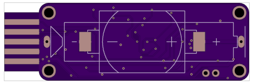
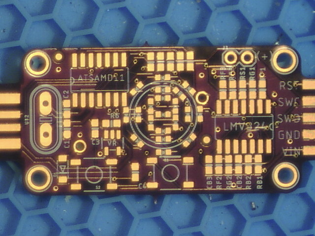
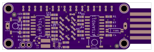
PCB
08/20/2019 at 22:09 • 0 comments![]()
PCB from OSHPARK ready to be populated. Used Eagle Cad for the design which is still free for small boards. Added github link for the project files to the page. A good place to learn Eagle Cad is from Adafruit and Sparkfun.
I am currently porting some of my older code to the SAM D11C. The SAM D21 peripheral structs are just about the same but the SAM D51 are not so a little difficulty there. I am using mattairtech's 4k boot loader and a blank Arduino sketch uploads to be about 8k leaving only 4k to work with. My initialization code for the timers and ADC are almost that much and that is only for the strobe. I am going to have to cut a lot out. If necessary then I will eliminate the boot loader to see if I can fit it all. Time will tell...
Clipper - A Clip on Tuner for Musical Instruments
Minimalist LED strobe style clip on instrument tuner using a SAM D11C and a piezo sensor with LED readout.
 .
.