Close
0%
0%

LiFePO4wered/ESP32

ESP32 IoT core board with flexible power and flexible communications

Public Chat
Similar projects worth following
One of my customers presented me with a challenge: for his smart city IoT deployments he needs an ESP32 based core board that combines the functionality of my wESP32 with the functionality of my LiFePO4wered products, to produce a board that could communicate over WiFi, Ethernet or Bluetooth and can be powered from battery, USB, DC input, solar panels or PoE.
And thus the LiFePO4wered/ESP32 project was born. :)

The design as implemented from the original idea has the following features:

Processing system

  • ESP32-WROVER-I module with 4 MB Flash, 8MB PSRAM and external U.FL antenna connection
  • Micro SD card slot for data storage
  • Separate NXP MKL17Z32VFM4 ARM Cortex-M0+ charge / system controller allowing ultra low power sleep with various wake events including RTC
  • Charge / system controller fully configurable by ESP32 over I²C bus

Power

  • Battery-backed: either by LiFePO4 cell or Lithium Titanate (LTO) cell for highest reliability due to predictable power on/off behavior and buffering of erratic input power
  • Long life with typically 2000+ cycles at 100% DoD when used with LiFePO4 cell
  • Extremely long life with typically 10000+ cycles at 100% DoD when used with LTO cell
  • MPPT charger to efficiently extract the most energy from a connected external power source
  • Convenient battery and external power connection with screw terminal block
  • On-board 18650 battery option
  • External power option DC 5V - 30V
  • External power option solar panel 5V - 30V
  • External power option micro USB 5V through optional wESP32-Prog module
  • External power option isolated Power over Ethernet IEEE 802.3af
  • OR'ed external power inputs can be present simultaneously
  • Integrated buck-boost to provide regulated 3.3V to the ESP32 system

Connectivity

  • WiFi 802.11 b/g/n using external antenna connected to the U.FL
  • Bluetooth 4.2 with Low Energy (BLE)
  • 10/100 Mbit Ethernet
  • GPIO header with UART, I²C, SPI, etc.
  • Sparkfun Qwiic connector allows easy solder-free development using existing Qwiic modules

Physical

  • Compact 75 mm x 55 mm PCB
  • Designed for wide -40°C ~ 85°C temperature range
  • Battery heater option for charging LiFePO4 in cold temperatures (not needed for LTO)

  • G5421CQT1U

    Patrick Van Oosterwijck09/28/2020 at 17:49 0 comments

    This project has stalled a bit unfortunately.  But I wanted to put a link here (to remind myself if nothing else :)) to investigate the G5421CQT1U.

    This is a $0.12 chip (in qty 1000) that seems to replace some of the functionality needed for the LiFePO4wered/ESP32 that was implemented as separate parts.  Since it needs 5V, it unfortunately still would require the SGM4552YN6G for level shifting the low voltage PWM signal from the micro and the AP7383-50W5 to regulate a 5V power rail, but it would integrate the functionality of the NCP81151 gate driver and the AON7804 dual MOSFET into a lower cost part with slightly lower RdsON (20 / 18 mΩ vs 21 mΩ typical), and I wouldn't need to use the wonky zener diode arrangement to make the NCP81151 do zero cross detection since the G5421CQT1U has a pin to enable that.

    I haven't dug through all the details yet, but it seems to be a part to keep in my power conversion toolbox.

  • More inspection and testing

    Patrick Van Oosterwijck11/13/2019 at 18:10 0 comments

    Finally found some time to test the rest of the board and things are looking good!

    Charging subsystem

    The first thing I tried to get to work was the charging subsystem.  I hit my first snag there.  In my last update I reported that I could turn power for the gate driver on.  I don't know what exactly I checked that time (maybe just that the enable pin to the gate driver regulator toggled), but turns out that was a lie. :)

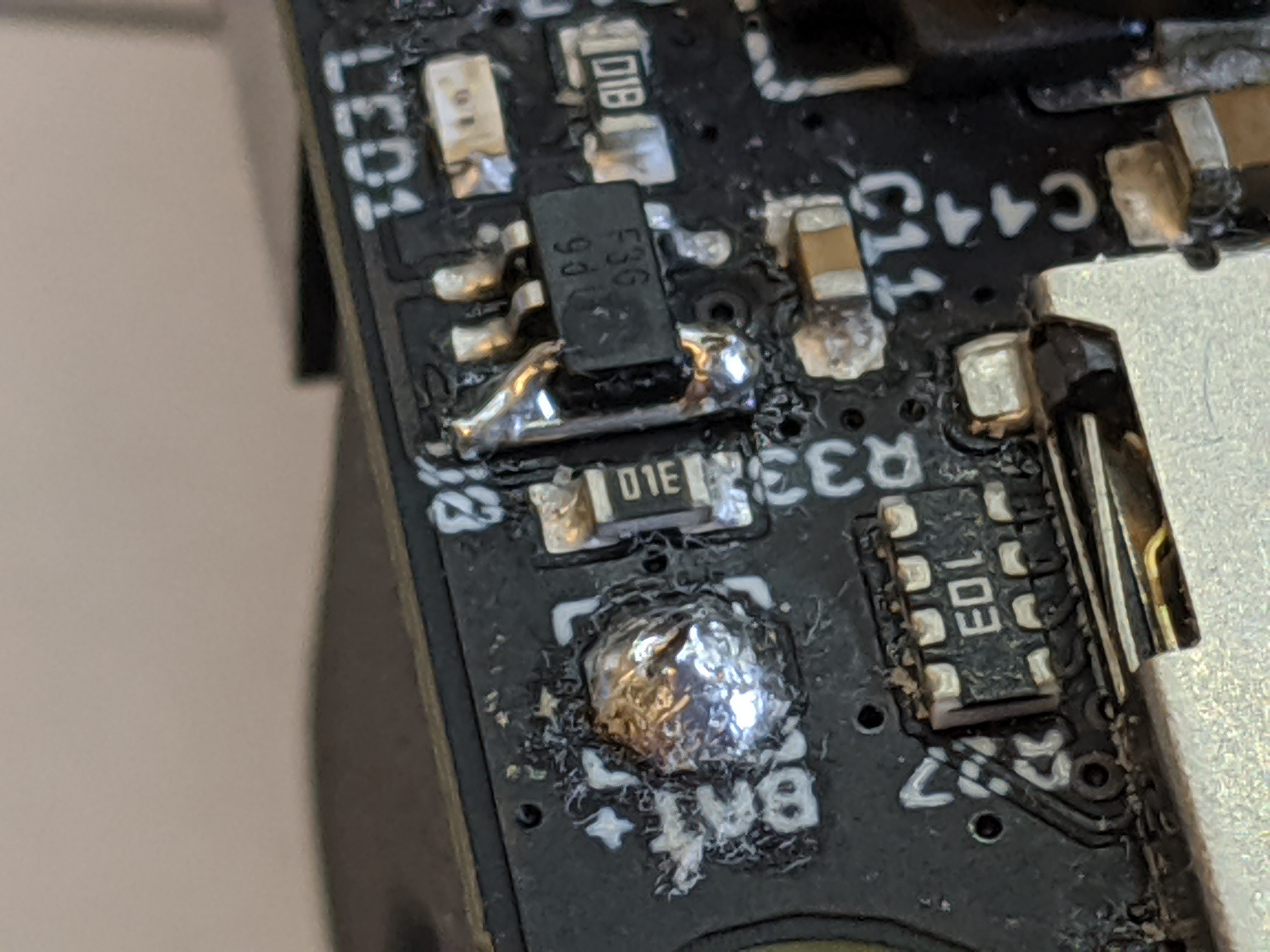
    What really happened was that yes, I could control the enable, but with voltage present on V+ no voltage would appear on the gate driver's supply.  Very puzzling.  Until I looked at the datasheet for the AP7383 regulator and figured out I had messed up my footprint!  I was sending the enable signal to the NC pin instead of EN!  Doh!

    So much for the rev 1 PCB design, on to rev 2.  Luckily, it's easy to fix on the 10 rev 1 boards I have:

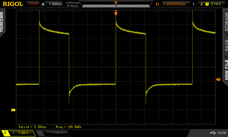
    So now I had power, I could start testing the charging subsystem.  I wrote a bit of code to produce a PWM signal and set it to 100/255.  Here's what the signal on the NCP81151 gate driver's PWM pin looked like:

    Excellent.  Exactly the weird signal levels required. :)  Recall that to use the synchronous rectifier's zero cross detection, the low level on the PWM input needs to be between 1.3V and 2.7V.  Looks like we're nicely between those levels.

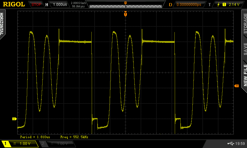
    In discontinuous mode, the synchronous rectifier needs to be turned off so we don't start pulling energy back out of the battery once the inductor current dies.  Looking at the switching node voltage we can see that indeed the synchronous rectifier is turned on, then releases, when in discontinuous mode:

    The flat high part (5V input) is when the high side driver is pushing current through the inductor.  Right after that we see a short stretch of 0V, this is when the low side synchronous rectifier is turned on.  This was confirmed by looking at the gate signal.  After the current through the synchronous rectifier gets low enough (zero cross detection), it is turned off and we get any remaining current flowing through the body diode, showing as -0.6V, after which the inductor voltage just oscillates a bit until the next cycle starts.

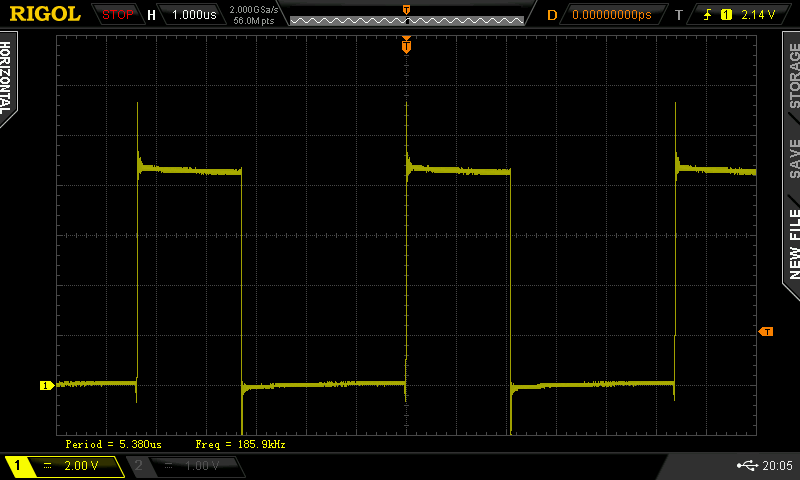
    Since I didn't have any control loop controlling the PWM yet (I just had it at a fixed value), I raised the input voltage to get the system into continuous mode.  Here's the switching node voltage in that condition:

    The same on-time for the high side driver, but at around 8.5V input.  Now there's enough magnetic energy stored in the inductor to keep the current going through the remainder of the cycle.  As you can see, the synchronous rectifier stays on and the voltage is 0V for the rest of the cycle.

    In this condition, I checked the voltage across the battery's current sense resistor and measured about 12mV.  For a current sense resistor value of 0.033 ohm, this means we were pushing about 360mA into the battery--it was charging! :)  Indeed, when looking at the battery voltage, I could see the millivolts counting up.

    I checked that the gate driver starts to operate at around 4V V+ input voltage.  This is great, I was planning to specify a minimum 4.5V input voltage.  So what this testing shows is that the charging hardware seems sound, all I need now is to implement the software MPPT control loop!

    Ethernet PHY

    The last main subsystem I hadn't tested yet was the Ethernet PHY.  From the #wESP32 I had already learned that this part is kinda finicky when it comes to its initialization.  In this project, I didn't add a dedicated part to handle this but am using the main charge/system controller to do it.  This is so its state is under user control and it can be enabled when necessary and doesn't such power when it's not in use.

    So I added some code for the bring-up and plugged in an Ethernet cable.  Nothing.  I fiddled with various things like the oscillator for a while until I eventually...

    Read more »

  • Initial prototype inspection

    Patrick Van Oosterwijck11/01/2019 at 23:06 0 comments

    The 10 prototypes arrived from KingTop, so it was time to see what doesn't work. ;)

    The first thing I did was plug in a PoE cable, to check whether that section works.  5V was showing up on V+, so that was one down!  This was a simple one because the PoE section is pretty much a copy of the #wESP32 circuitry, only with a smaller flyback transformer.

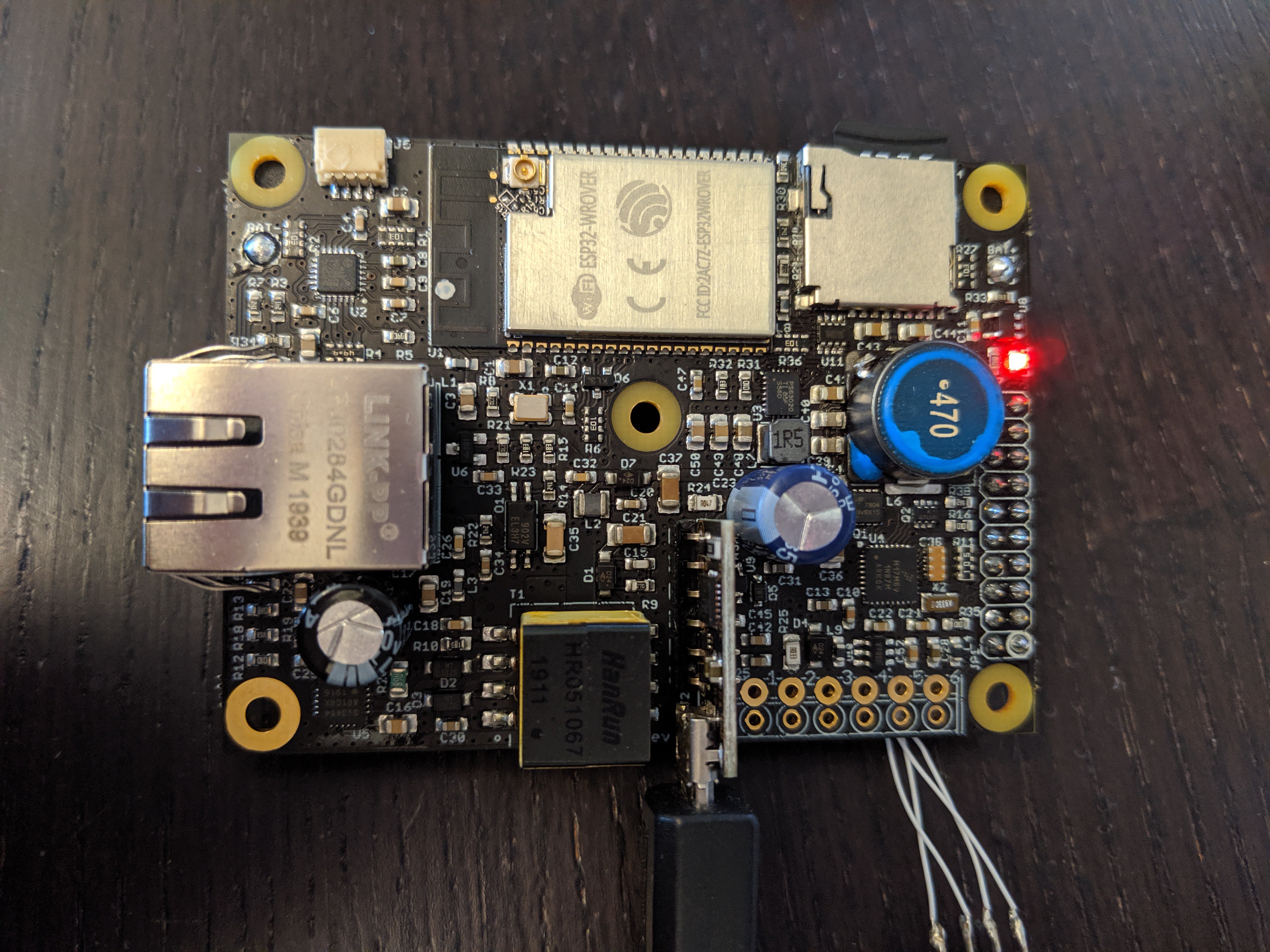
    Time to connect a battery and my J-Link and see if I can talk to the charge/system controller:

    And we have a blinking LED, excellent!

    From there, I started to write some firmware to check stuff and turn various parts of the system on and off.  I verified I can go to sleep and wake up with the 32 kHz crystal, I can turn various parts of the measurement system on and measure input voltage and current and battery power and current.  I can turn the switched battery output on, and the power for the gate driver.

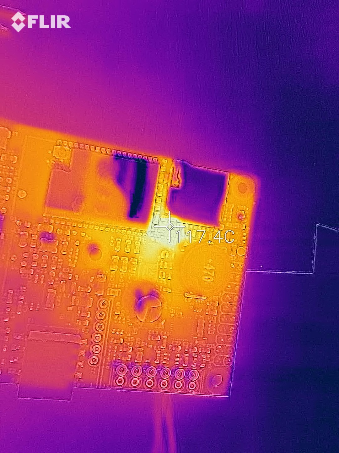
    I hit my first snag when I tried to turn the 3.3V system power for the ESP32 on.  Suddenly, there was a lot of heat near the buck-boost converter.  Uh-oh!  Luckily, I have a thermal camera to figure out where exactly the heat is coming from:

    That's not the buck-boost converter, it's the little I2C level shifter U11 that's trying to burn up!  What's up with that?

    Upon closer inspection, turns out KingTop messed up this time.  On 4 of the 10 boards, the level shifter was mounted 180 degrees turned.  Doh!

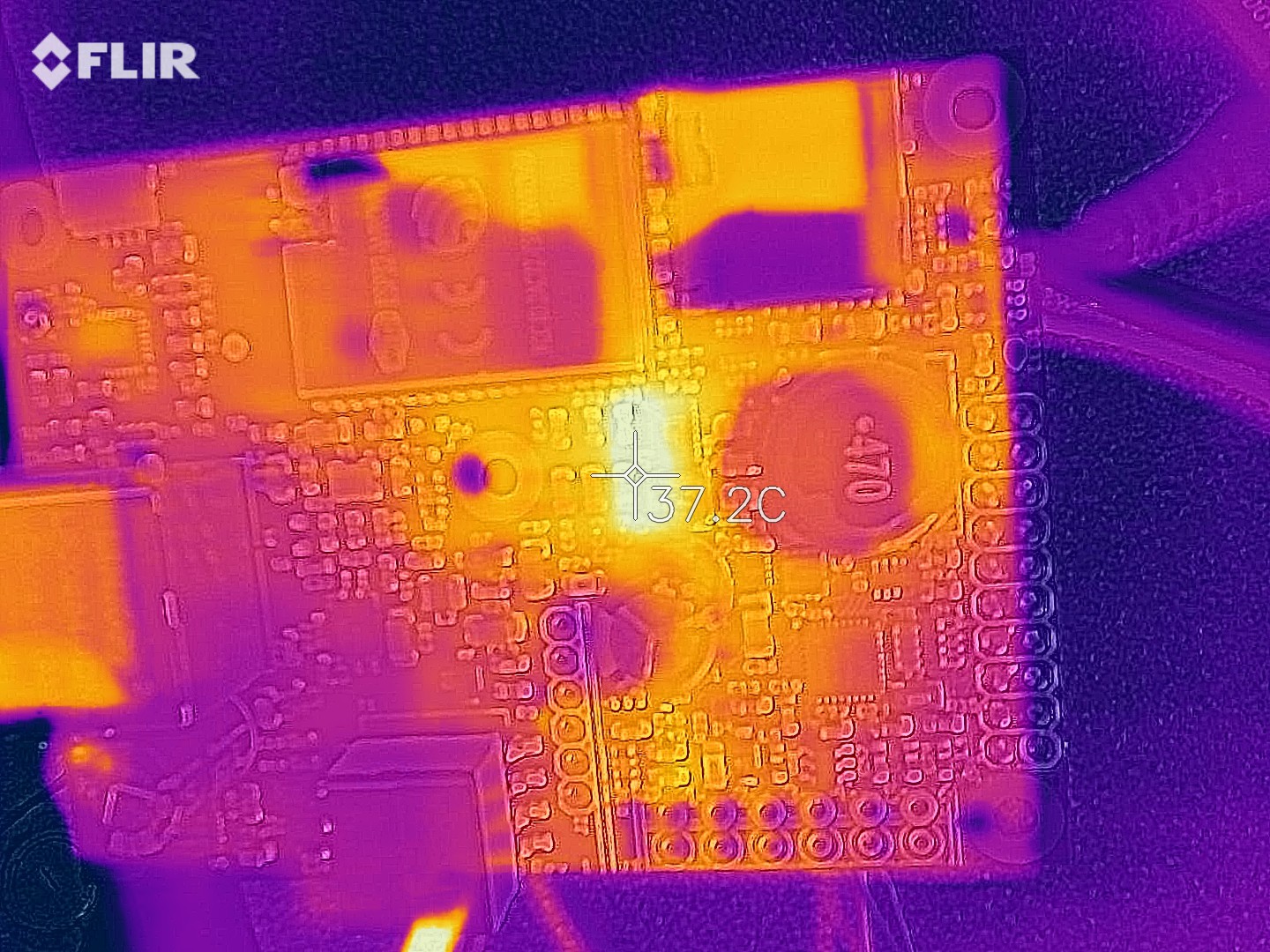
    This particular chip was fried, so I replaced it with another one on my test board.  Tried to turn the 3.3V system power on again, no heat this time!  3.3V on the system supply from a 3.2V battery, the converter is doing its job.  Time to test it under some load, let's pull 1.1A in addition to what the ESP32 is pulling:

    37°C at 1.1A, that chip isn't even breaking a sweat!  Of course, more testing will have to be done over the full 1.7V to 3.6V input range, but this is very positive.

    Once I had system power, I could start testing the rest of the board.  The ESP32 programmed right away through the wESP32-Prog submodule.  I put MicroPython on it again for testing, very convenient.  I connected Sparkfun's Environmental Combo Breakout to the Qwiic connector and a scan of the bus reported 2 devices.  I hooked up an antenna to the U.FL connector and connected to an access point, got an IP and was able to load data.

    I had some trouble with the micro SD card at first.  Various guides talked about an SDCard object that didn't seem to exist in my MicroPython.  Turns out this is pretty new, so I went looking for the latest image.  I found that there are now official images with PSRAM support available!  Woohoo!  Loaded the latest one, and now MicroPython reports 4M free space instead of 150K, awesome!  Also, the SDCard object exists in this image and I could load a file from the SD card.

    The only major parts that haven't been checked yet are the charging system and the Ethernet PHY.  Both require some firmware work on the charge/system controller first.  But the first tests have been very positive up till now.

    One other thing I'm still trying to figure out is high sleep current on the system/charge controller.  I'm getting ~270 μA sleep current while I was expecting only a couple μA.  I have checked by removing supply ferrite beads and about 166 μA is going into the controller's digital VDD and 60 μA into the analog VDDA.  I'm not sure yet where it's going.  These modern chips are so complex with a gazillion things that can be or need to be turned on and off manually and it's likely I've screwed something related to that up in my code.

  • KingTop PCB assembly

    Patrick Van Oosterwijck10/30/2019 at 22:32 0 comments

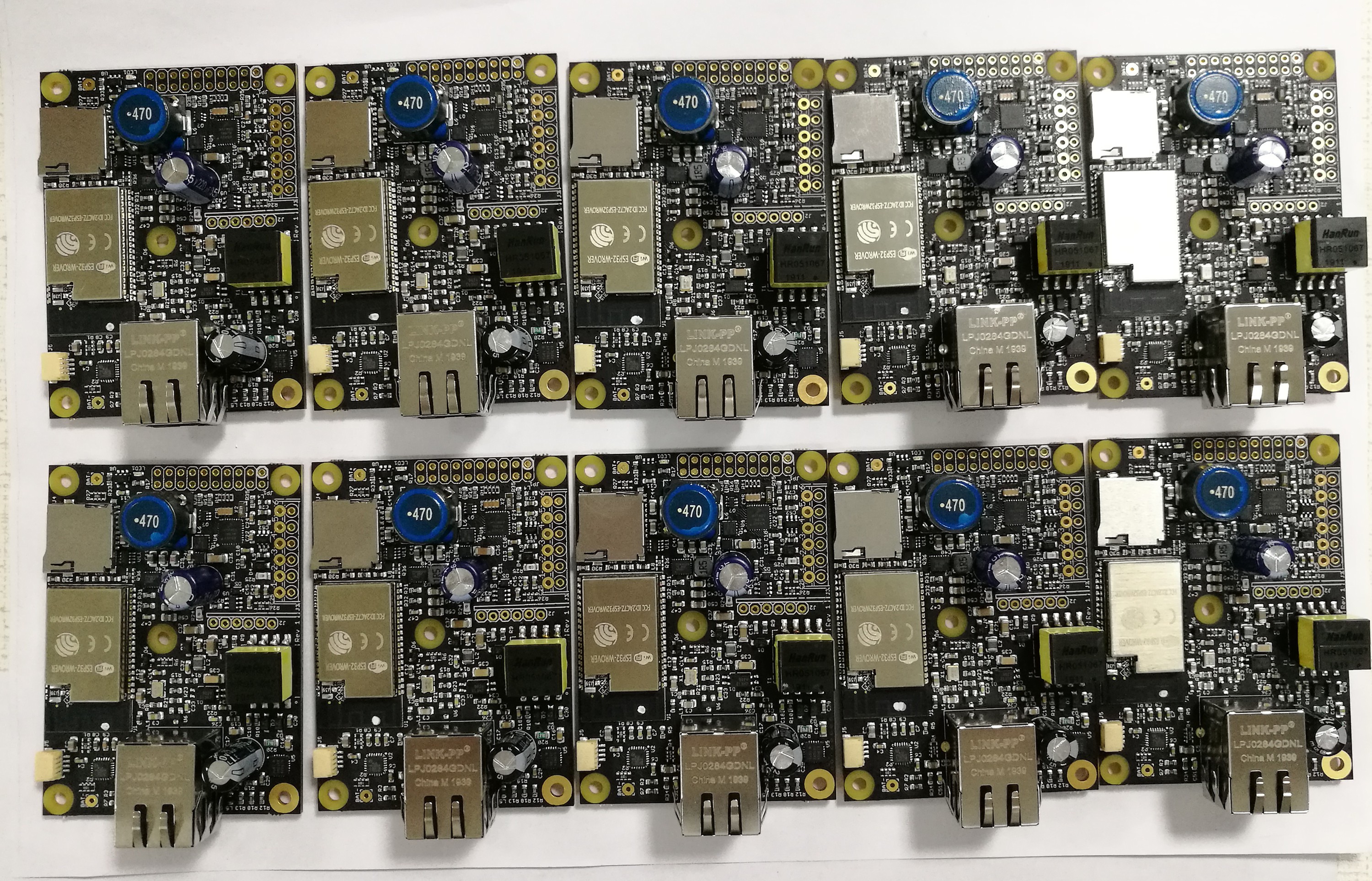
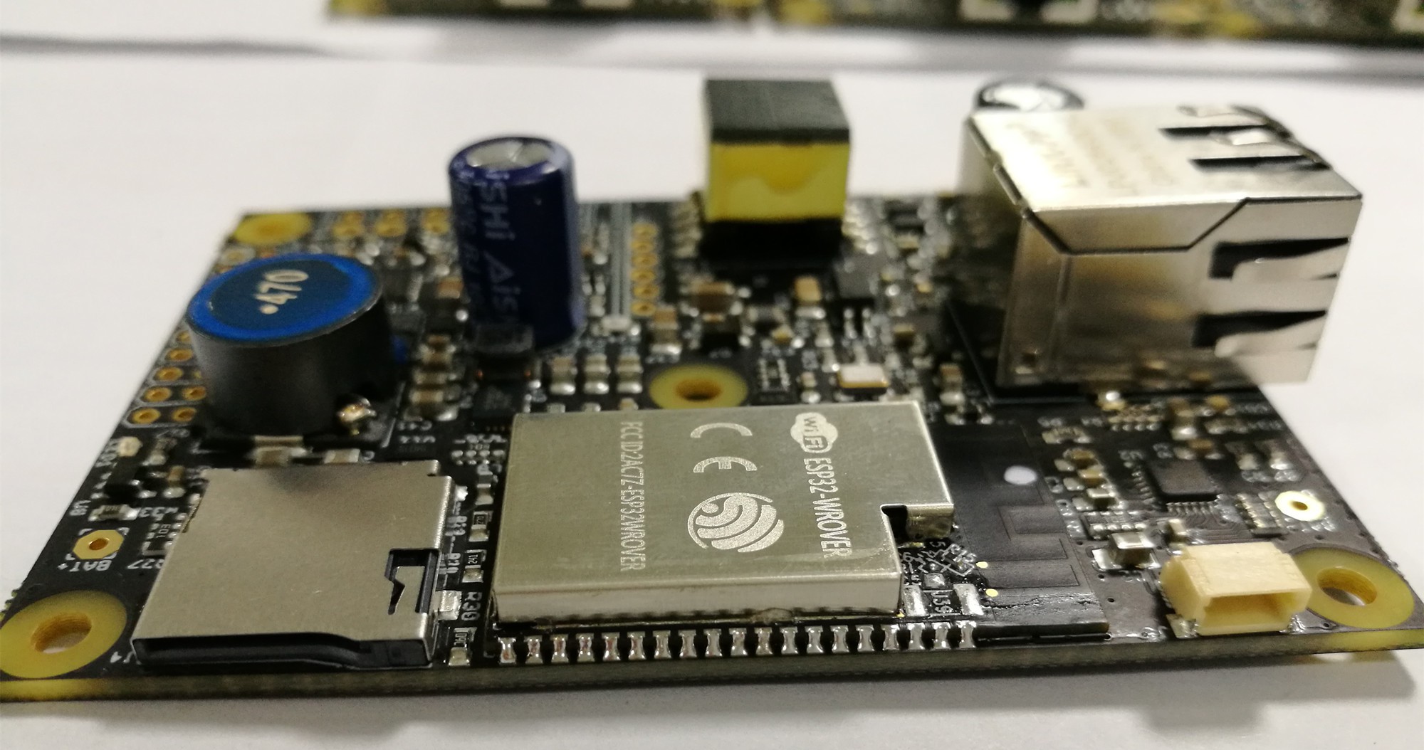
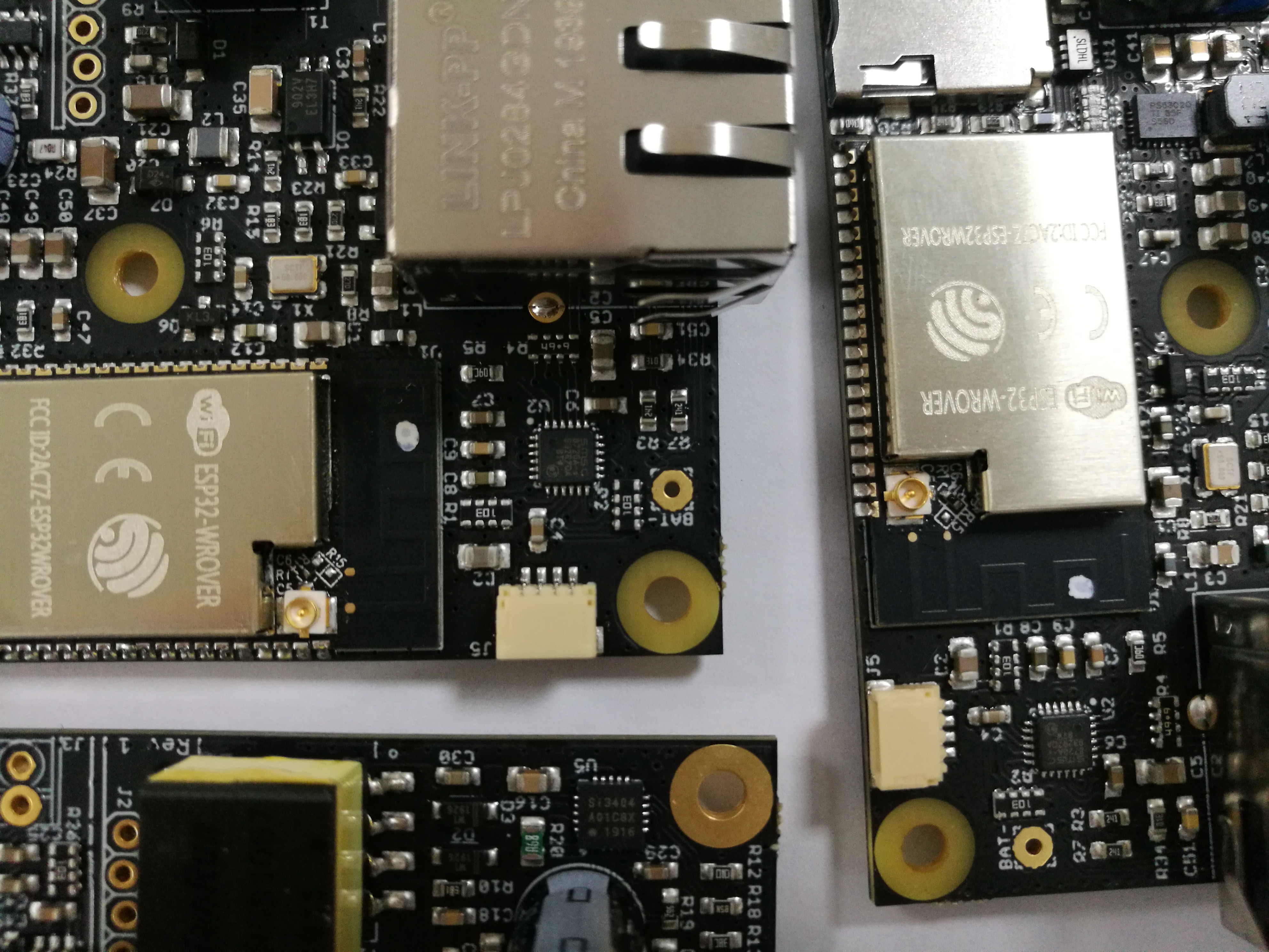
    I got word from KingTop Technology that they were done building the 10 prototypes.  They sent me pictures for visual inspection:

    Looking good overall!  However, I spotted a problem:

    They populated ESP32-WROVER (using PCB antenna) modules instead of ESP32-WROVER-I (U.FL antenna connector)!  Since this is not exclusively a PoE/Ethernet board (that's only one of the possible power/connectivity options), it is very likely the board will be used with WiFi and/or Bluetooth.  Since it was designed from the start to use an external antenna that can be mounted outside the box, the position of the ESP32 module is such that the on-board antenna is pretty much useless.

    I contacted KingTop about it and suggested they either had to replace the modules or "convert" them to ESP32-WROVER-I by installing a U.FL connector and changing the active antenna connection by repositioning R15 on the module.  They chose the latter option and reworked the boards:

    The result looks good to me and I had them ship the boards.  Let's hope the fix will work as I assumed and a U.FL antenna will work as expected now!

  • PCBs manufactured

    Patrick Van Oosterwijck10/09/2019 at 03:34 0 comments

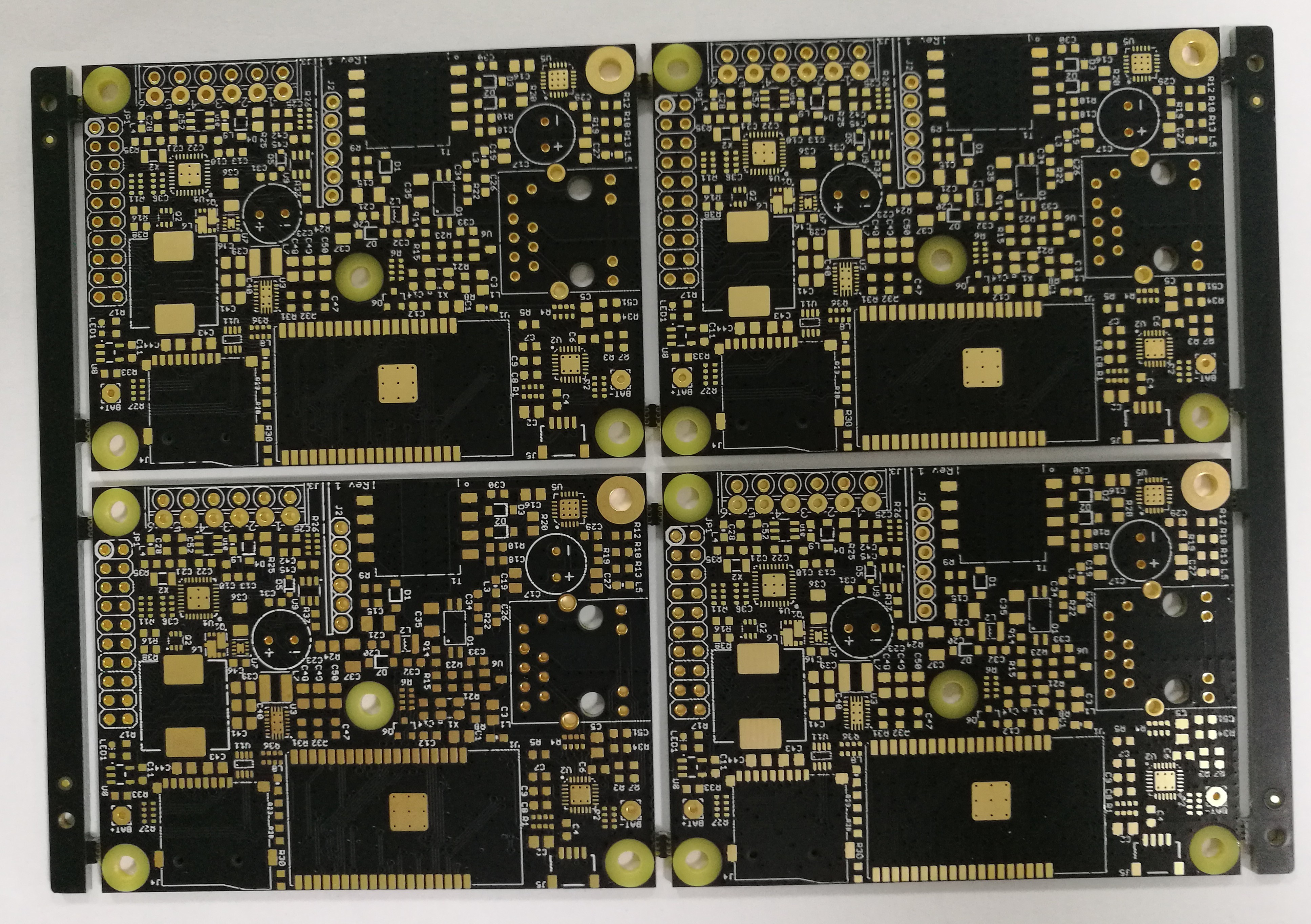
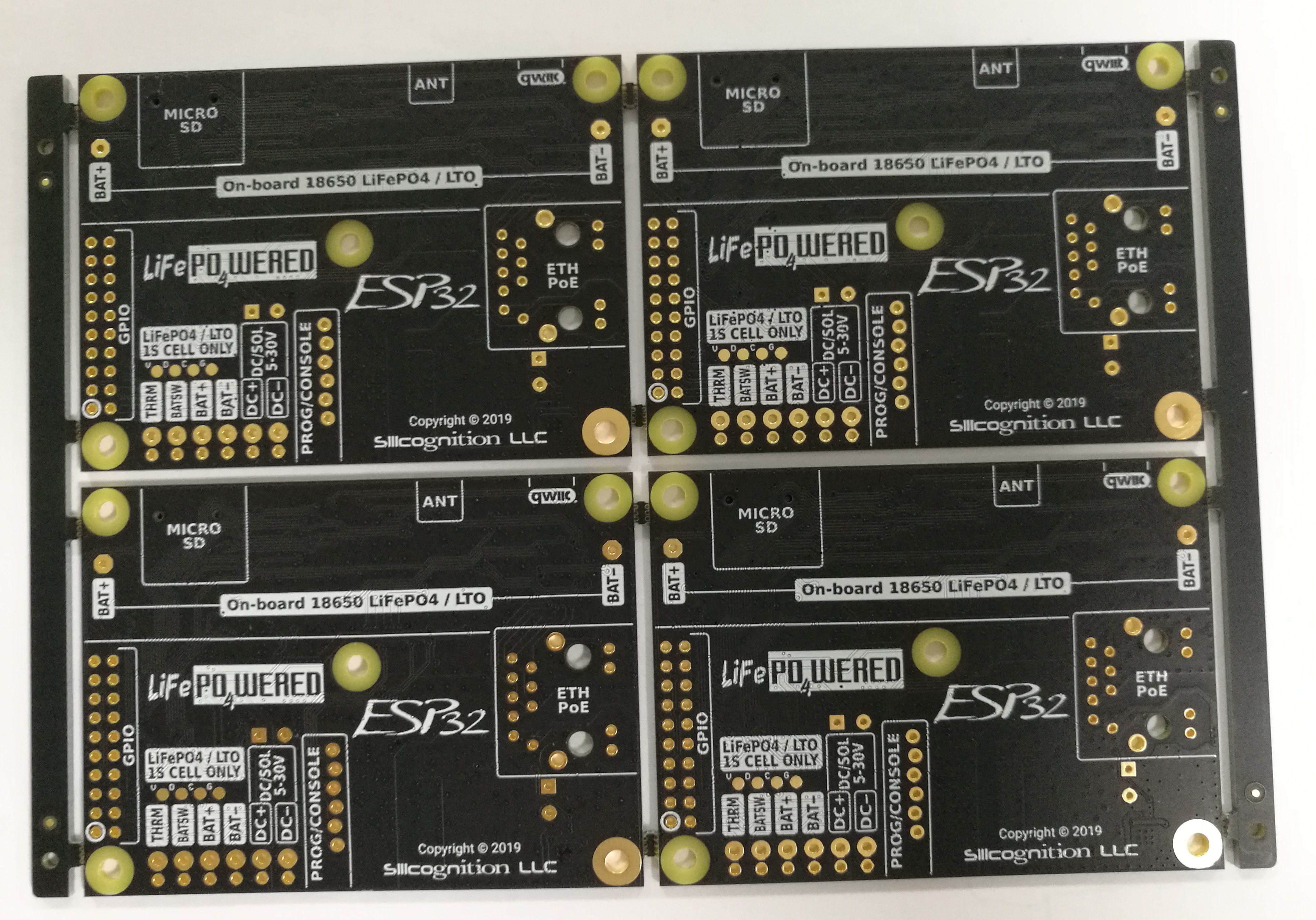
    It's starting to get real!  I got word from KingTop Technology that the PCBs are manufactured, and they sent me these pictures to review:

    Looking good!  I think the legend I added turned out quite nice and should be helpful.

    Meanwhile I've started work on firmware for the charge / system controller, but to be honest I haven't made as much progress as I'd hoped.  Always so many other things to do.  Still, there's one thing I can mention: in addition to I2C access like the #LiFePO4wered/Pi+, I also intend to add a serial console that can be used to access and control the internal registers of the controller!

  • PCB layout done!

    Patrick Van Oosterwijck09/17/2019 at 16:57 0 comments

    The PCB layout is done!

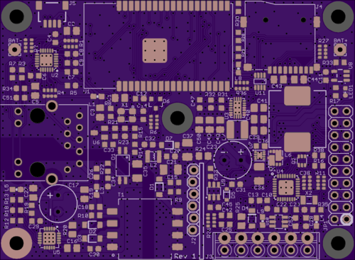
    This was a hard one.  In hindsight, it might have been better to go to a 4-layer board to get it done faster.  But now it's done, I'm happy with the result and I think it will work well.  To get all power and signal traces where they need to go all over the board, I needed to have extensive routing on both layers, so there isn't much left of a ground plane on the bottom layer.  But with plenty of judicious via stitching between ground on the top and bottom layers, I think it's still a solid enough ground plane overall.

    The PoE section on the bottom left is very similar to that found on the #wESP32.  This time I'm using a smaller flyback transformer and smaller diode on the secondary side because we only need about 6W here, not 13 W as on the wESP32.  The Ethernet PHY has moved to above the Ethernet jack.  This means it's closer to the jack than on the wESP32 so performance should be as good or better.

    We moved from an ESP32-WROOM-32 to a ESP32-WROVER-I module to take advantage of PSRAM for larger projects and have plenty of space for MicroPython.  The positioning of the module may look bad for antenna performance, but since we use the -I version with U.FL connector and an external antenna, the on-board antenna is not used, and the module's position is fine.

    Programming and serial console is provided by a wESP32-Prog submodule as on the wESP32, the footprint for this option (J2) is located central on the PCB along the bottom edge as on the wESP32.

    Most of the new stuff is on the right side of the PCB.  On top is a micro SD card slot, wired for 1-bit access from the ESP32.  1-bit is not the fastest but it's a compromise to preserve enough ESP32 pins for GPIO connections to external circuitry.  I wanted to have at least enough pins available for simultaneous use of I2C (2 pins) and SPI (4 pins), and with the pins taken up by the Ethernet RMII bus (8 pins) and the PSRAM (2 pins), and the unfortunate number of input-only pins on the ESP32 (4 pins), 1-bit SD access was as good as we were going to get.

    Central on the board is the buck-boost converter that generates the 3.3 V system power from the battery voltage, which can range from 1.71 V to 3.6 V (minimum LTO to maximum LiFePO4 voltage).  The converter should be able to provide at least 1 A even at the lowest input voltage.  The central location worked out well to use a star topology for system power distribution.

    To the right and below this is the microcontroller based charging system.  This was the hardest part to layout because the various current loops need to stay as small as possible to reduce EMI and maintain high performance.  I went with the NCP81151 based gate driver to minimize cost and take advantage of the built-in zero cross detection and synchronous rectification for maximum efficiency.  This came at the cost of more components for regulation and level shifting, so it was a very tight squeeze to pack it all in.  I had to use resistor, capacitor and transistor arrays to make it work.

    External connections are clustered on the bottom right.  The reason for this is that I wanted to keep the top edge of the PCB clear of through-hole components so it is possible to install an optional on-board 18650 battery holder there on the bottom of the PCB between the BAT+ and BAT- pads.  Since the battery holder makes the mounting holes along the top unreachable, a central mounting hole was added as well.  The on-board battery should be a good option for development and bench-top use, but I expect that most production installations will use an external battery connected to the screw terminal connector along the bottom, along with DC/solar power input, if that is used.

    The GPIO header needs to be in the bottom right as well for the same reason, to not interfere with the optional on-board 18650 battery.  This made the layout harder because a lot of traces needed to be...

    Read more »

  • Current sense with micro, and battery heater

    Patrick Van Oosterwijck08/28/2019 at 15:23 0 comments

    I got a FRDM-KL27Z development board to be able to test some things in the design before committing to them in a PCB layout.  Initially I had intended to use this to build and verify the complete charge buck converter, but that was before I realized I need a proper gate driver.  I am no @greg davill, you won't see me put together a dead bug prototype with 0.5 mm pitch QFNs under a microscope.  So a complete charge converter prototype won't happen before the PCBs are made.

    But, I decided the dev board would still be useful to do some testing of the ADC for current sensing.  One of the reasons I chose the MKL17Z64VFM4 is because when I was designing the custom project this is based on, I liked the built-in ADC and reference of the MK02FN64VLF10 I was using for that project and found I could do current sensing directly with the micro using the differential 16-bit ADC inputs.  I decided I should verify whether this chip worked as well for the purpose.

    Battery heater decisions

    Surprisingly, the need for ADC data came out of the need to settle on a particular implementation for the battery heater driver.  I am driving the heater from the battery voltage in this design.  The idea is to again make things more automatic and easier for the user.  In the #LiFePO4wered/Solar1, I drive the heater from the incoming voltage.  The downside is that no MPPT happens, the heater has to be carefully designed to not overload the solar panel and make the voltage collapse.  In this board I want to power the heater from the battery (much more predictable), and supplement as much power from the external input as available.  I also want to use the solar power most efficiently, so MPPT is desirable for the heater power.  Instead of building a completely separate MPPT converter for this purpose, I'm using the charger MPPT converter and divert all available power to the heater up to the point where all power comes from the input.

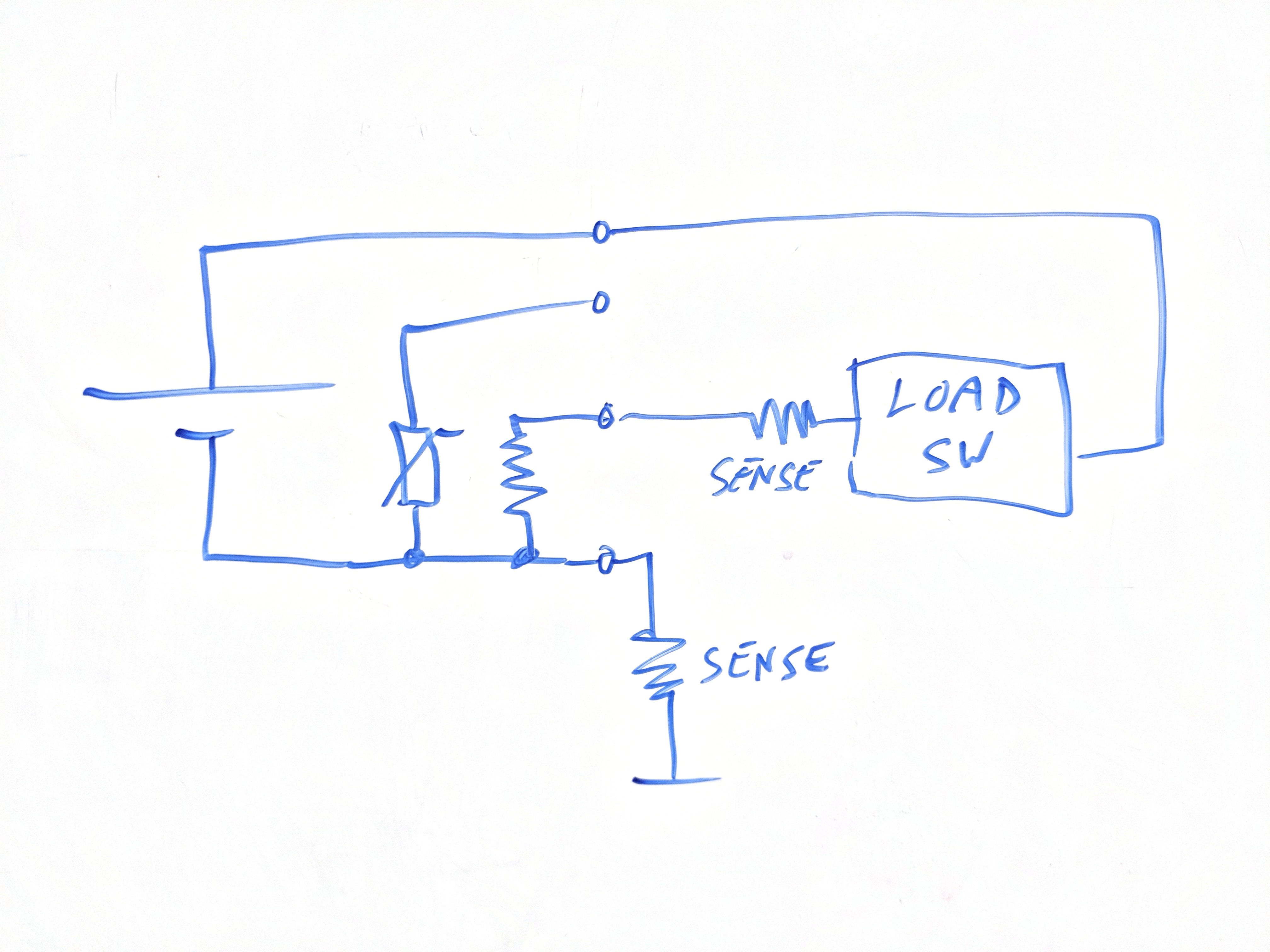
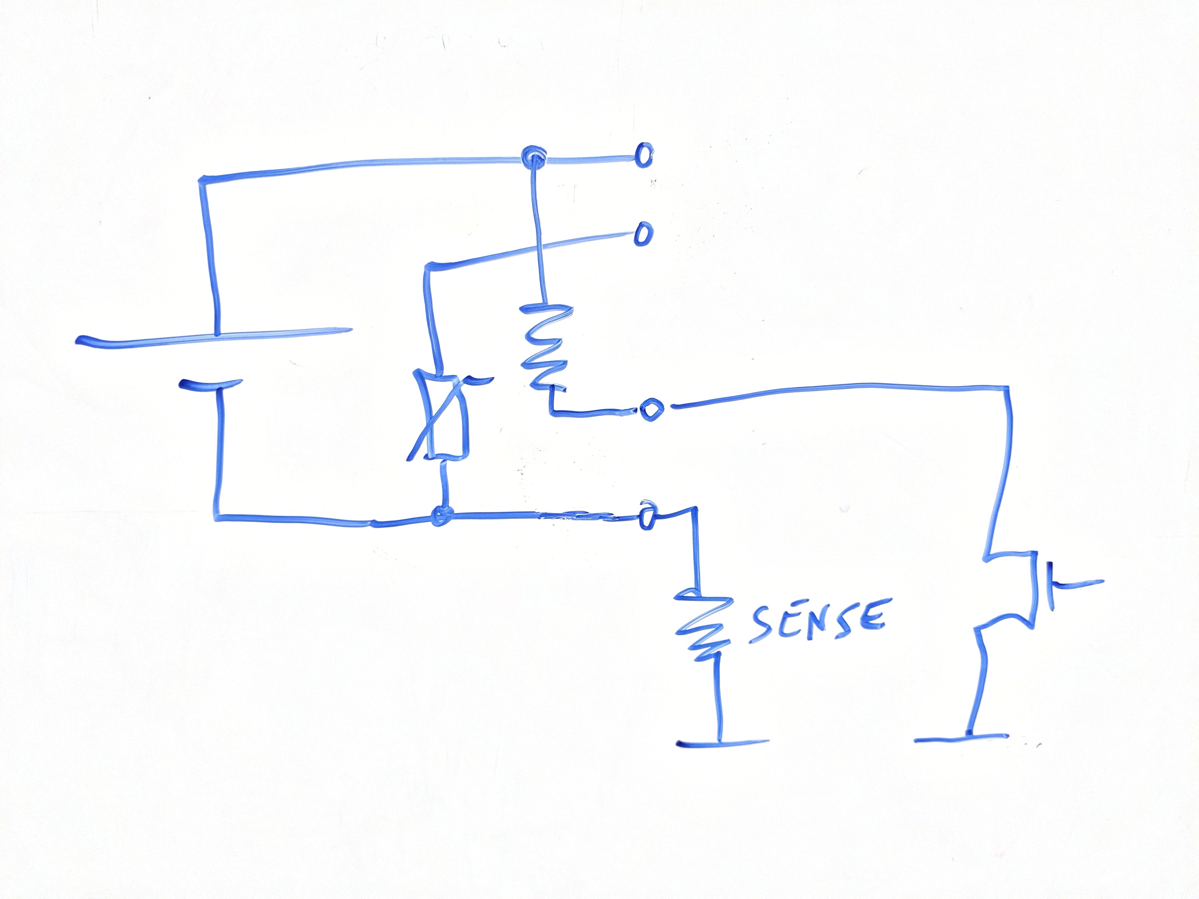
    There are two topologies I considered:

    1. Heater connected to battery ground, driven by an external voltage.  This requires the board to drive a voltage to the heater.  Just using a MOSFET to switch this voltage isn't safe, the output needs to be properly protected so I would preferable be using a load switch.
    2. The other option is to connect the heater to the battery's positive terminal, and pull the other end to ground from the circuit.  I looked hard to find low side load switches with integrated current limiting, but for the life of me I couldn't find anything suitable.  If anyone has suggestions I'm all ears.  So this would most likely be implemented as a MOSFET with thermal fuse.  I'm not a fan of thermal fuses, they are kind of sloppy.

    In topology 2, you can see a single current sense resistor.  It's the battery current sense, but it can also measure the heater current.  More correctly: it can measure whether the heater driver is diverting all power from charging the battery to heating the battery.  We may not know what the current is exactly, but we know when the battery current is zero and can implement something in the MPPT control loop to maintain this.

    In topology 1, you can see two current sense resistors.  One is to measure the battery current, the other measures the heater current.  It is necessary to add the second current sense resistor because the battery current sense provides no visibility into the heater current, we sense the current whether it flows through the battery or the heater.  The upside is that we still know the absolute current value.  We can build a control loop to make the heater current match the battery current.  The downside is that we need another current measurement, and it is a high side current measurement (near supply voltage).  This means we have to use a differential ADC channel for this.

    Testing the ADC

    "Remember kids, the only difference between screwing...

    Read more »

  • MOSFET gate drivers

    Patrick Van Oosterwijck08/25/2019 at 05:42 0 comments

    So in a previous project log I had been trying to figure out how to design this without a proper gate driver, and drive the charger MOSFETs directly from the micro.

    I have since come to the conclusion that this is a stupid idea. :)  In the log referenced above, I mentioned two purposes of a gate driver:

    • Provide level shifting to drive the gates with sufficient voltage.
    • Provide powerful drivers that can quickly charge and discharge the power MOSFET's gate capacitance, to ensure fast switching for high efficiency.

    The latter is what made driving the gates directly from the microcontroller already look bad.  But there's another function gate drivers provide that I had forgotten:

    • Provide a floading well for the high side MOSFET gate driver!

    Level shifting the high side gate drive signal does not just involve shifting the high level, but the source voltage for this MOSFET (and "ground" reference for the driver) is shifted as well every cycle!

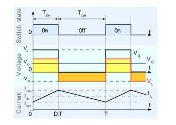
    Details can be found in the Wikipedia article on buck converters, but here's the graph from it:

    As you can see, the switching node voltage (Vd in the graph) continuously switches between 0V and Vi, which in my case can be up to 28 V.  The gate driver ensures that the high side MOSFET gate keeps the correct voltage level relative to Vd, no matter what Vd is doing.

    Proper gate drivers contain a special circuit feature called a floating well that takes care of this and a level shifter that translates the incoming PWM signal into a signal that is referenced to this node that's bouncing up and down.  There's just no way that I can easily replicate this functionality without using a gate driver.  Turns out people knew what they were doing when they started making these parts and they exist for a good reason. :)

    MIC4600 solution

    My biggest objections to adding a gate driver were cost and PCB space.  When I started searching for gate drivers that would work with my minimum signal voltage levels of 1.71 V and maximum input voltage of 28 V, I quickly found out that there was a good reason I had chosen the MIC4600 in the customer project this is based on: it's pretty much the only part on the market that fulfills both requirements.  Unfortunately, the lowest price I've seen for them is $0.978 in qty 1000.  That's a significant cost adder.

    I wanted to know what else was out there.  What was I missing out on with my extreme requirements?  Were there any requirements I could relax just a bit so a lower cost part could work?

    NCP81151 solution

    So I removed my search filters and went for the lowest cost suitable part i could find: the NCP81151, which is only $0.175 in qty 1000!  In addition to the low cost, it has some other advantages.  It's a synchronous driver which means that instead of having to control both high and low side MOSFETs from the micro, I can provide a single PWM signal and the gate driver will manage the high and low side drivers by itself.  In addition, it has zero cross detection on the low side driver which makes it automatically behave correctly if the system goes into discontinuous mode (inductor current falls to zero).  This is a really big deal to me because there's no good way I know to handle this from the micro other than to estimate and run in asynchronous mode for low currents and synchronous for high currents.  Having the zero cross detection makes this headache go away.

    What would it take to make this part work in my design?  The first obvious thing: it requires 5 V, not 28 V.  The floating well can take 35 V so my input voltage range is fine, but I need a voltage regulator to supply the gate driver itself.  In some way this isn't any different from the MIC4600.  It also runs from 5 V, but has a regulator integrated on the same chip.

    I need a regulator...

    Read more »

  • Entering Hackaday Prize

    Patrick Van Oosterwijck08/25/2019 at 04:17 0 comments

    So I've entered this project into the Hackaday Prize 2019 contest.  Not sure if it's a good idea or not.  I'm entering very late.  There are many other good projects that jumped on the opportunity right away and have collected tons of followers and likes (and bootstrap money) by now, while I've just started to document my early stages of development.  Some projects look like they have fully functional hardware at this point, while I have just a whiteboard sketch.

    But, since it's about designing products this year, I really can't let it slide, since that's what I do. :)  We'll see if I can manage to attract some attention from the judges with what I have documented by now.  I'm hoping that my track record of turning the #LiFePO4wered/Pi+ and #wESP32 into successful products will be helpful.  It just didn't fit into my schedule to kick off the project any earlier. 

    I considered letting this year's prize pass and submitting the project to next years prize, but who knows what theme it's going to be about next year?  Probably nothing that would fit a product like this.  Designing something that's not just a hack but a product, that's something I can do.

    I hope they're not getting me on some technicality this time.  Like: I have not yet detailed my license because there's nothing to license yet!  When there's a schematic, it will be CC-BY-SA like most of my stuff.  There isn't a detailed description yet because I'm still designing the thing so I don't know what it's going to be yet.

    So, let's just see what happens. :)

  • Charger MOSFETs and how to drive them

    Patrick Van Oosterwijck08/22/2019 at 19:43 0 comments

    Gate drive level concerns

    I had unexpected difficulties in finding good power MOSFETs to implement the charge converter.  My desire to have a large 5 to 28 V input voltage range turned out to be making life difficult here.  It's easy enough to find MOSFETs with high Vdss breakdown ratings.  It's also easy enough to find MOSFETs with low Vgs thresholds.  But having the two requirements combined in a single part turned out to be harder than expected.

    A cursory glance at part specs might make you think differently.  There are plenty of parts that are listed as having low threshold voltage, but usually the threshold voltage is specified for silly low drain currents such as 250uA or 1mA.  I need a part that is fully on, with low RdsON, at the minimum microcontroller voltage of 1.71V.

    The reason is that I want to keep the charge circuit as simple as possible.  In the custom project that inspired this charger's implementation, I was using a boost converter to generate 5V gate drive voltage and a MIC4600 gate driver chip to drive the MOSFETs.  For the LiFePO4wered/ESP32 I want to do away with those parts and drive the converter MOSFETs directly from the microcontroller, if at all possible.

    Keeping these requirements in mind, while also keeping cost and size down, and considering Safe Operating Area (SOA) so I don't have MOSFETs burst into flame at high input voltages this time, the best option I have found is the DMN3020UFDF.

    With a Vdss breakdown voltage of 30V, a maximum RdsON of 40 milliohm and drain current of 10 A specified for a Vgs of 1.8 V, plus the best looking SOA graph I could find, it looks like this part should work well to implement an efficient charger without needing to add a gate voltage booster or separate gate driver chip.

    Switching speed concerns

    At least when it comes to gate drive voltage level that is.  What I'm still worried about is the switching speed I can achieve when driving the MOSFETs directly from the micro.  After all, the function of a gate driver like the MIC4600 is not only to provide the right gate voltage levels, but also to provide powerful enough drivers to quickly charge and discharge the power MOSFET's gate capacitance.

    The DMN3020UFDF specifies a total gate charge of 15 nC at 4.5 V Vgs, 27 nC at 8 V Vgs.  This seems to be scaling linearly (makes sense since Q = C * V), so I'm assuming about 12 nC gate charge at 3.6V and 6.6 nC at 2 V.  I will be driving the gates from high drive capable pads of the microcontroller.  They are specified at 20 mA (0.5V drop) for 3.6 V supply and 10 mA for supplies less than 2.7 V.  This gives an estimated switching time of 600 to 666 ns.  That is... slow.  Compare this to the typical switching time of about 15 ns for the MIC4600 gate driver.

    The problem with slow switching is twofold.  First, it directly limits the switching frequency because obviously you want on and off times that are significantly longer than the transition between them.  Second, during switching is when the MOSFET dissipates the most power as heat.  When fully off, the voltage across a MOSFET is high but no current flows, so there's no power loss.  When fully on, the current though the MOSFET is high but the voltage across it is really low (due to the low RdsON) so power loss is low.  It is during a switch between on and off that significant values for both voltage across and current through the MOSFET are present at the same time, causing power loss (P = V * I) that is dissipated as heat.

    Heat causes circuit problems and reduces efficiency.  The solution to minimizing this problem is to switch less often (less time spent in switching transitions).  But lower switching frequency demands a larger value inductor, which will either have to become physically larger and more expensive, or will have higher resistance, again reducing...

    Read more »

View all 14 project logs

Enjoy this project?

Share

Discussions

AshleyVinning wrote 10/02/2023 at 17:43 point

This is an exciting project, I ESPecially like the use of LTO batteries to complement a Solar panel.  Excellent! Were you able to get this board working? I'm trying to do something similar, minus the PoE, which I now want having seen yours!

  Are you sure? yes | no

Don Johnson wrote 11/15/2019 at 01:14 point

You had me particularly excited with the name of this project - I've just recently purchased one of your Solar1 boards to power an ESP32. I was hoping this was basically an ESP32 on that board (something I'd buy a couple of!). The PoE seems like a bit of a funny fit to me - it's giant and seems a bit unexpected to have a bunch of tiny, embedded devices all hardwired. That's what's nice about these kinds of projects, you can build whatever is needed for the use case.

Regardless, I'll be following along with interest though, I appreciate the logs.

  Are you sure? yes | no

Patrick Van Oosterwijck wrote 12/23/2019 at 01:26 point

Thanks Don!

I agree, this is a bit of an "everything, including the kitchen sink" project, because that's what my customer needs.  It seems that in the "smart city" space, you can never predict what power and connectivity will be available and/or acceptable to the paper pushers in charge, hence the desire for extreme flexibility.

I agree it would be nice to make a "tamed down" version some time.  The goal is that the IP developed for this will be flexible enough to apply to other projects without too much porting effort.  The #LiFePO4wered/Solar1 is a bit bare-bones in configuration and with the IP developed here I would love to make a software configurable version. :)

  Are you sure? yes | no

Similar Projects

Does this project spark your interest?

Become a member to follow this project and never miss any updates