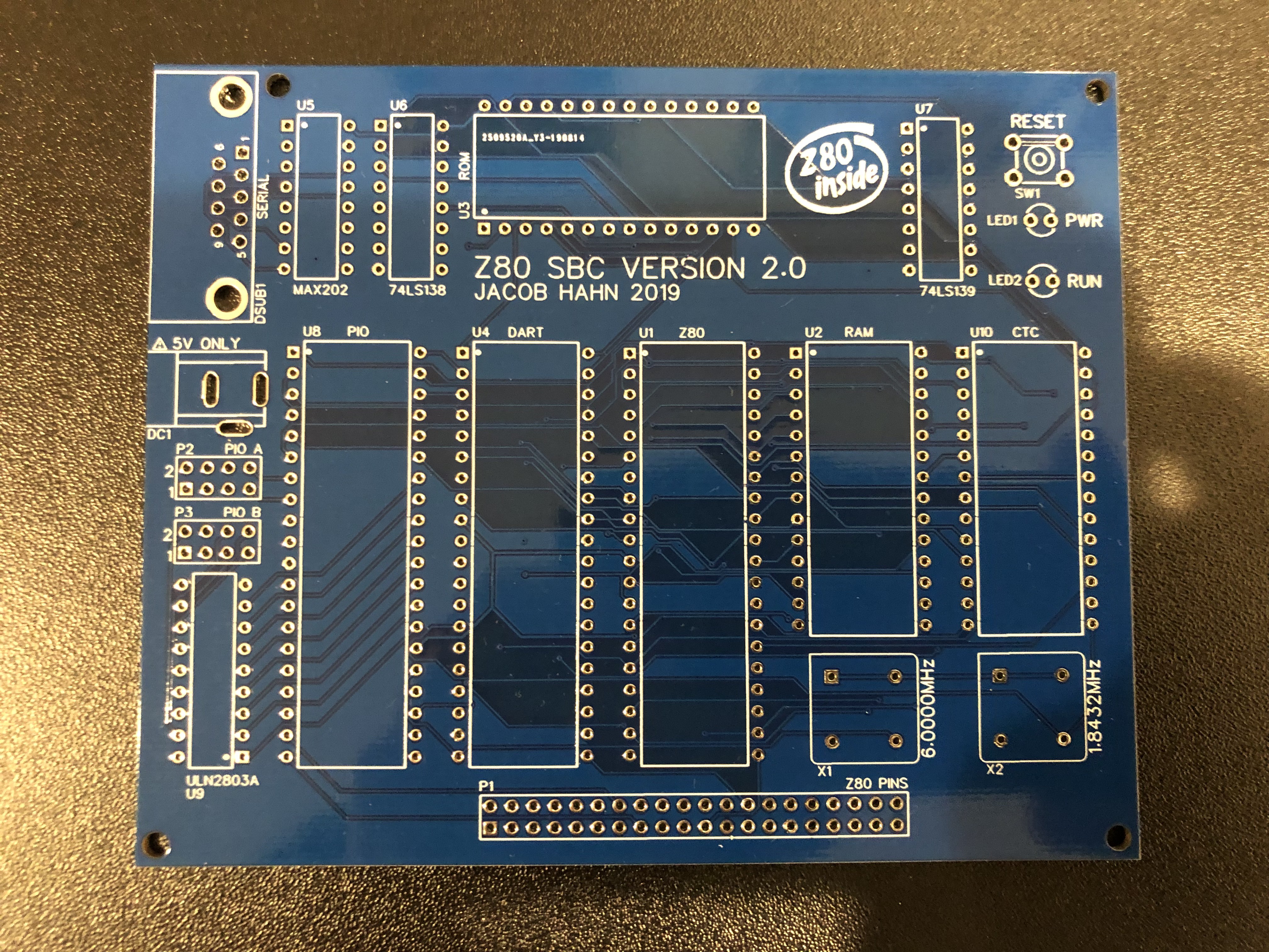
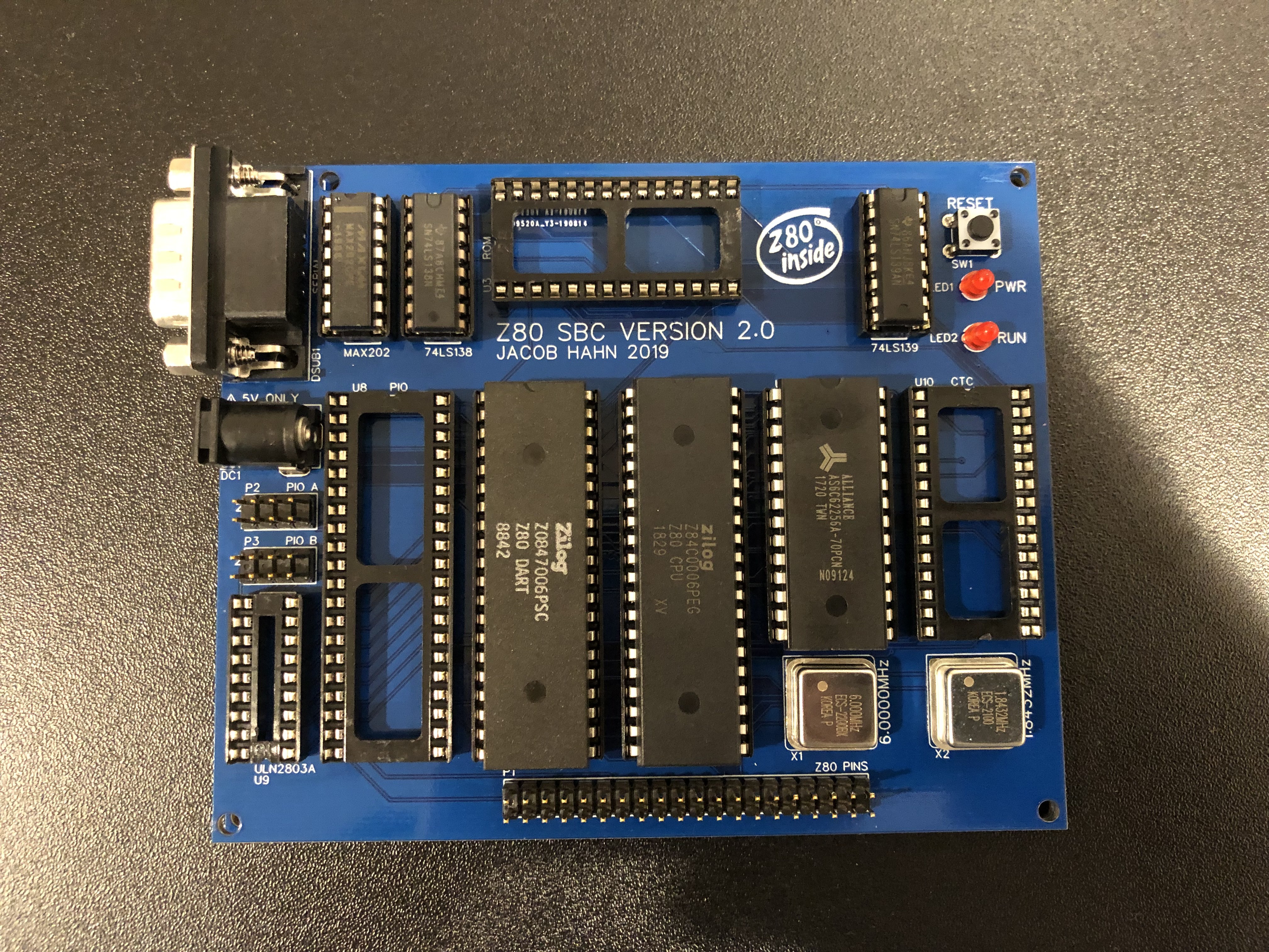
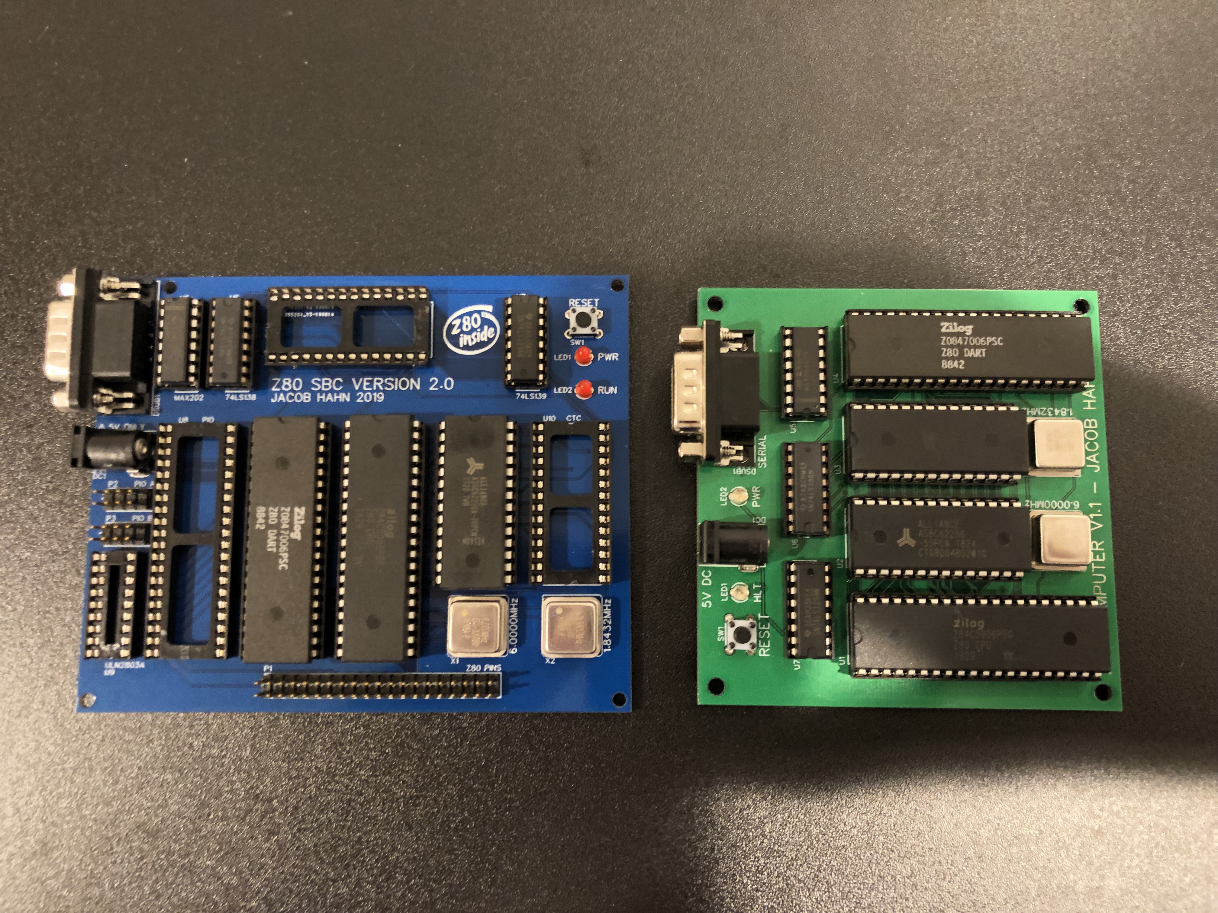
A few days ago, I received an order of Z80 SBC PCBs for prototyping. I’ve been spending the past few days finding components and soldering, but I finished a board today.

Unfortunately, I made the mistake of not soldering the large ground terminals of the serial port, thinking I wouldn’t stress the port enough to cause damage. Of course, once I plugged in a serial cable, the port flexed slightly, ripping the pad of pin 5 (ground) of the port off of the board. When I plugged the board in to test the output of BASIC, I got a few recognizable words but with lots of gibberish mixed in. I went ahead a used a enameled wire to connect pin 5 to a different ground pad, but the result was the same, so something else must have happened during the process of soldering or from the port damage.

I checked the board thoroughly for any damage, such as broken traces, but could only find some scraped solder mask here and there on the back. Nothing major, and certainly nothing that would affect operation.
Luckily, I already have some new components ordered and I should be able to have a new board made by this weekend.
I’m also working on updating the PCB layout a bit for v2.1, including moving the ROM to the right a bit (so that I can use my IC prying tool with it!), a larger ground trace on the transistor array, and extended PIO pins. Thanks for the ideas, @Ken Yap!
Stay tuned, as I’ll be adding details and info throughout the week.

 Jacob Hahn
Discussions
Become a Hackaday.io Member
Create an account to leave a comment. Already have an account? Log In.
Could it be that the through hole for pin 5 is effectively a via that goes to other parts, say the MAX202, and the stress has broken the via, so you have to make more wire bridges?
Are you sure? yes | no
Unfortunately, that’s not the case. The through hole connects directly to a ground plane. The issue could really be about anything, from bad connections and traces and contacts to damaged ICs, and my multimeter is in storage after having just moved, so I can’t test easily. I’m almost completely sure it’s not my schematic or board layout though. I’ll be able to get my meter within a few days and look around before building a new board hopefully, and maybe I’ll find the issue.
Are you sure? yes | no