 rand3289
-
1Software
Software is available here: https://github.com/rand3289/FiberGrid
Git clone. Change to the directory and type make. Build the hardware and connect it to your computer. Run fc (fiberCal) and generate fiberinit.h by pressing "s". Play with fc sliders to get the best fiber detection (green squares around fibers). Add fiberinit.h, fibergrid.h and fibergrid.cpp to your project or run ft (fibertest.cpp). Use FiberGrid::read() or FiberGrid::readNormalized() to get sensor values! Run your project to see the sensor values on a debug screen. Comment out FIBERGRID_DEBUG to disable driver debug screen. Currently both fiberCal and "the driver" programs rely on OpenCV library being installed to read the camera.
-
2Making the hardware
There are two versions of FiberGrid. One for R&D and testing. It features detachable fibers that can be disconnected from the grids. Both fiber ends are glued into small 3D printed connectors. The second is a "production version" where fibers are glued directly into the grids of the camera and light modules on one side and have a connector (plug) on the other. This allows packing more fibers into the grid. The diameter of the connector is greater than a plain fiber and takes up more grid space. I am using a 1mm fiber. If you need more than 200 - 300 sensors, try using 0.5mm fiber. It should allow for a denser grid.
* Choose between the two designs. Current R&D version models allow for 16 or 86 connections to each module. The "production" version has 100 and 216 hole plates.* Download FiberGrid 3D models and print the parts. I used Creality Ender 3 to print my parts. Cleanup the holes with a 1mm drill bit, a bit with diameter of your cladding and a ~4mm bit for large holes.
* Assemble the light and camera modules as shown in the pictures below.
* Cut the fiber into pieces of appropriate length depending on your project. If you have chosen the R&D version, glue the connectors onto both fiber ends with superglue. Otherwise glue one connector to one fiber end and glue the other end directly into the grid of the camera module. Do the same for the light module fibers. Plug unused holes with pegs (R&D version) or fill them with black silicone.
* Print some sensors or design and print your own sensors with a 4mm diameter holes for fibers coming from the light module and going to the camera module.
![]()
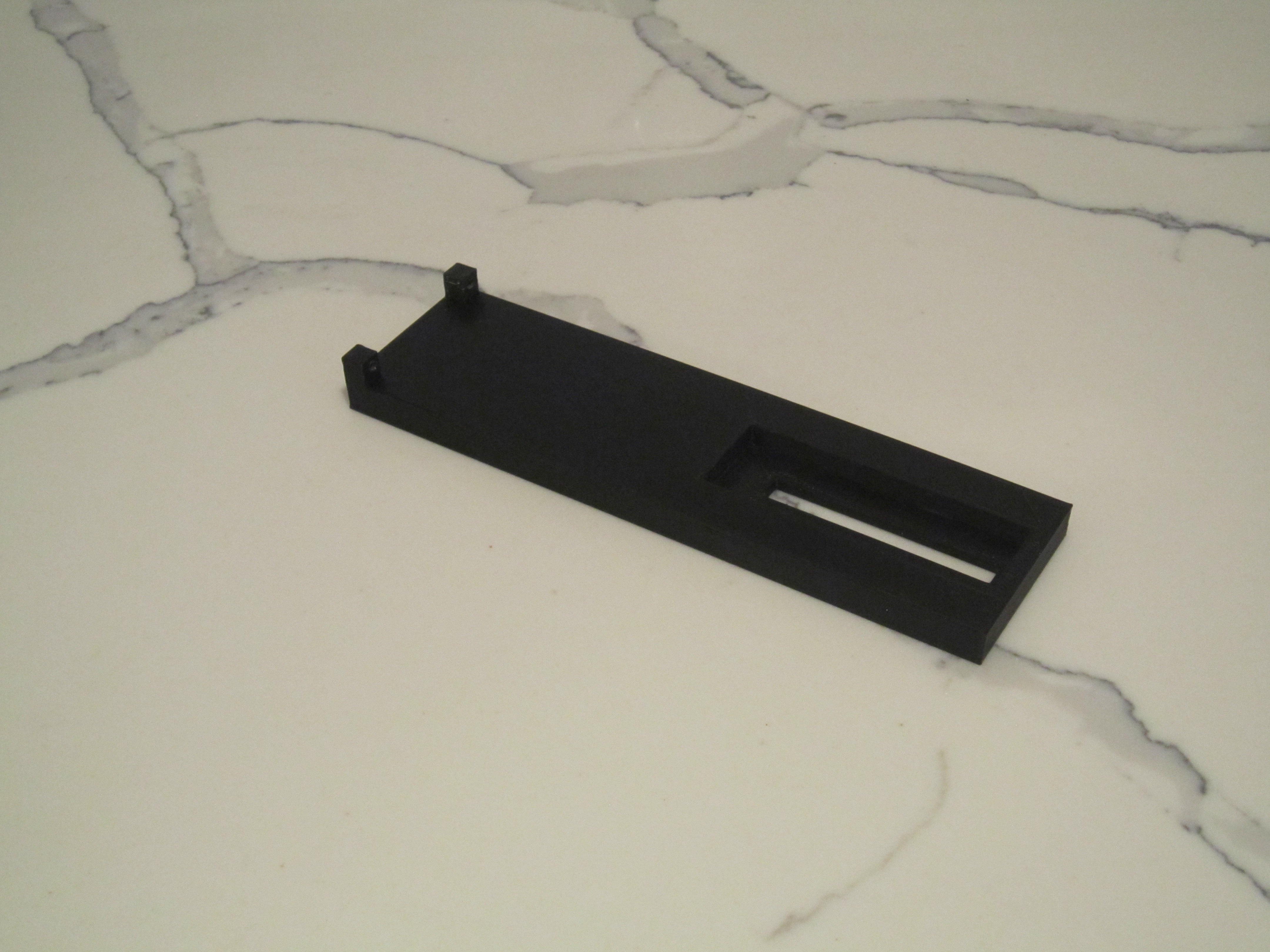
fibergrid bench is the largest component and takes several hours to print. Try using 20% infill and a 0.3 mm layer height.
![]()
The grid with 16 plug holes is attached to the fibergrid bench with two screws.
![]()
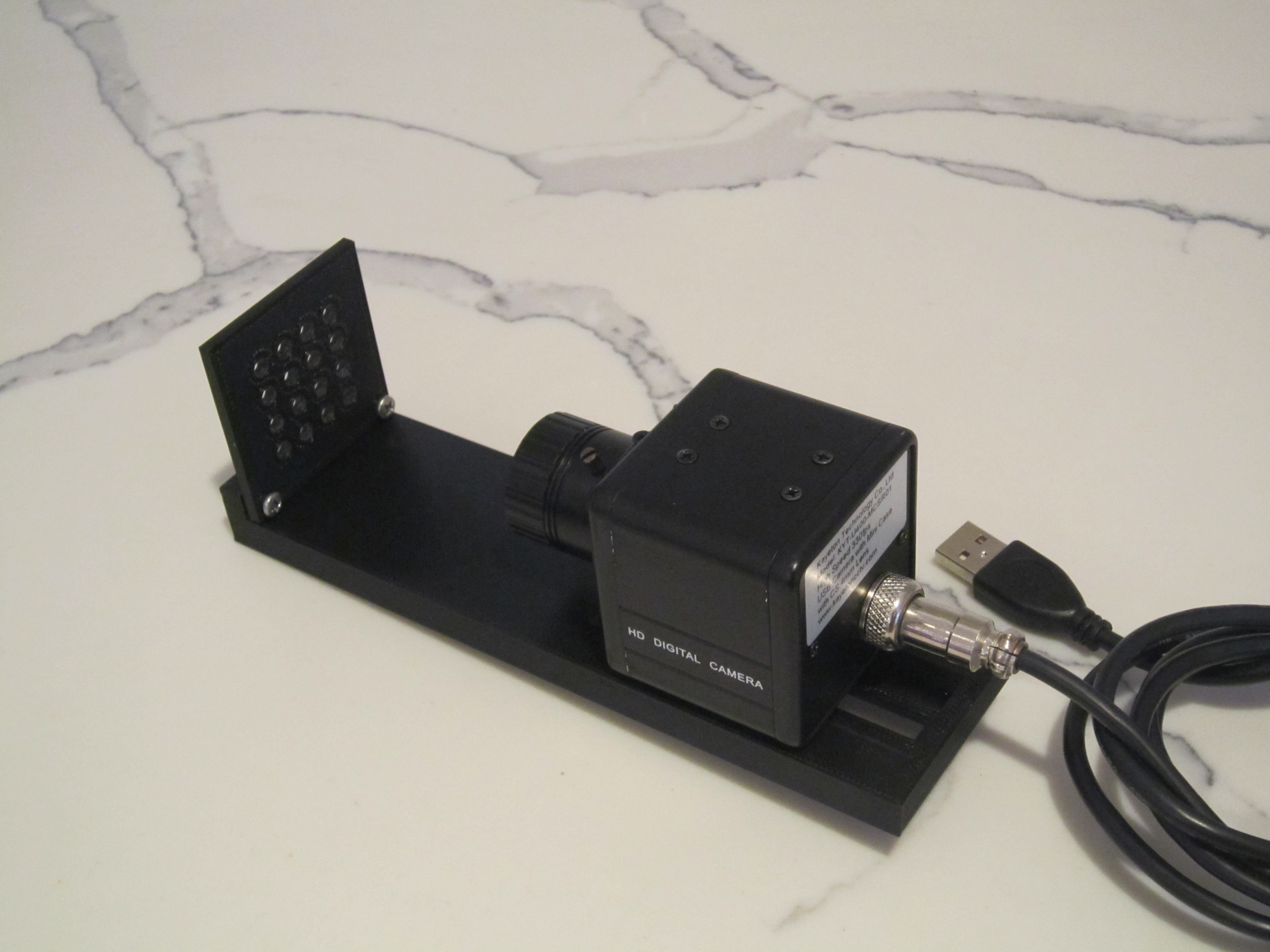
In the picture above the camera is attached to the bench with a bolt.
![]()
The shroud is pushed onto the grid and the camera slides into it. After that the camera bolt is tightened.
![]()
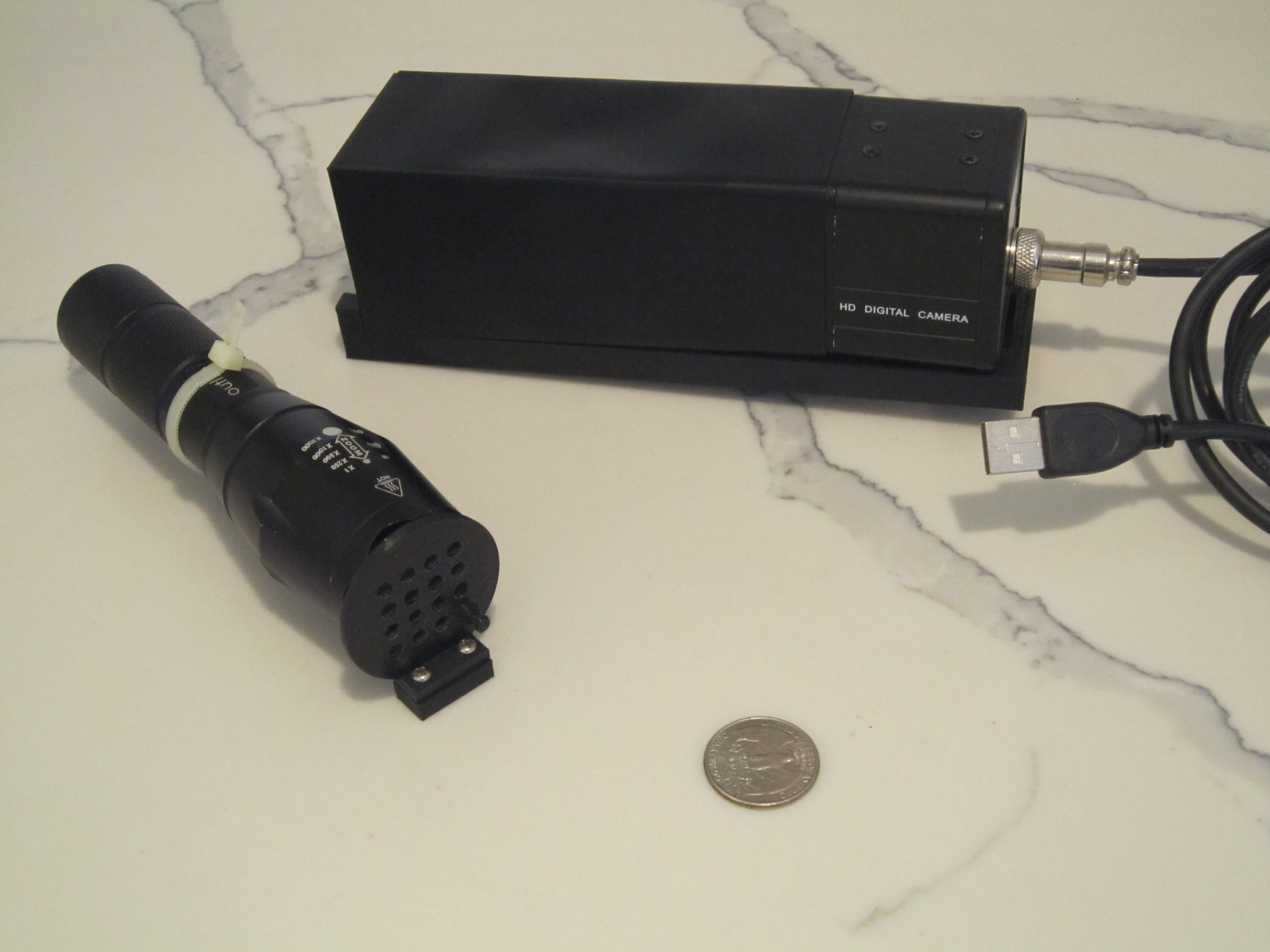
Light module shown here is already assembled with two screws and a ziptie holding the flashlight to the base. Flashlight front should not be touching the PLA parts since they can melt or deform.
![]()
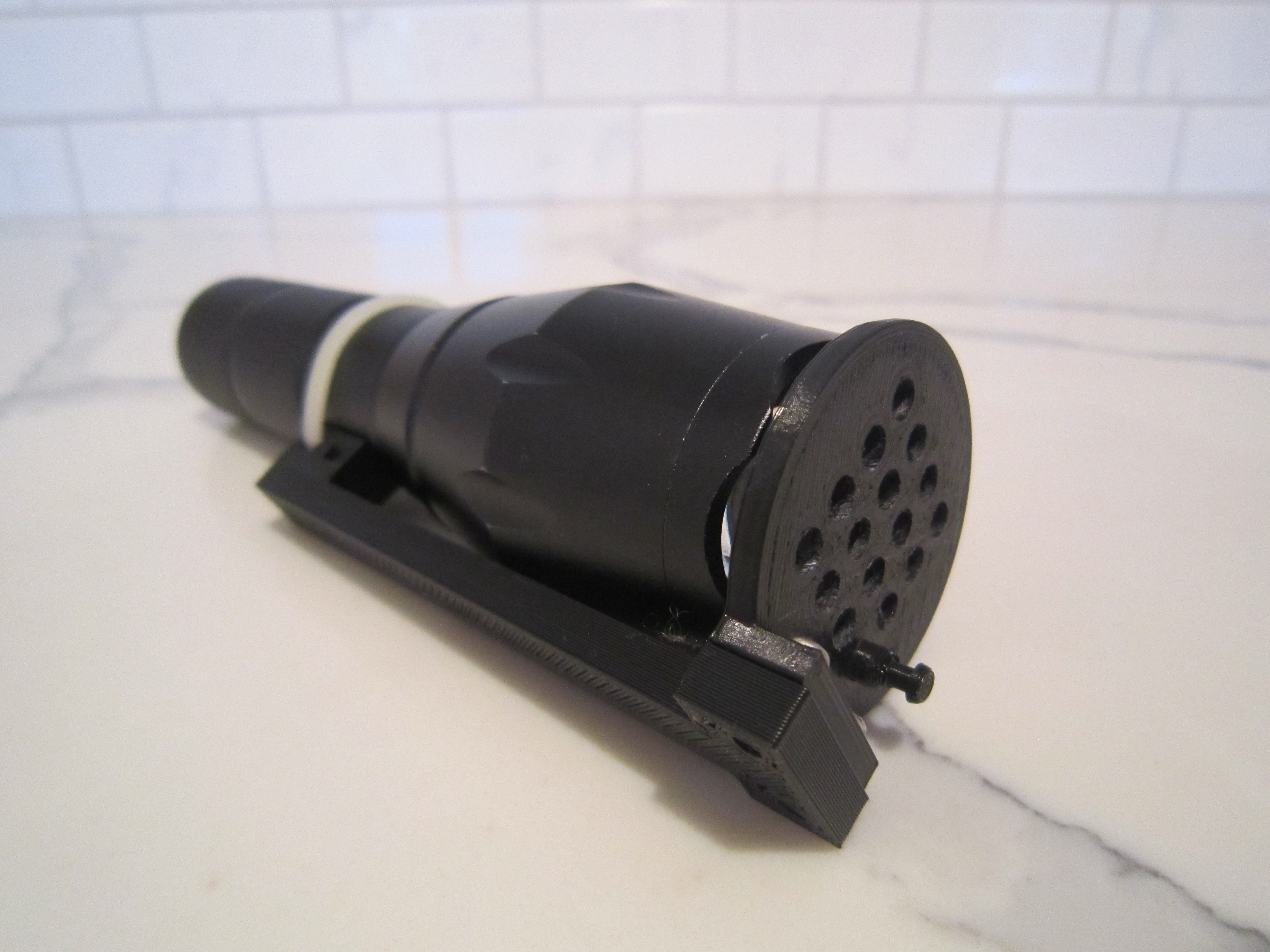
Closeup of the assembled fibergrid light module.
![]()
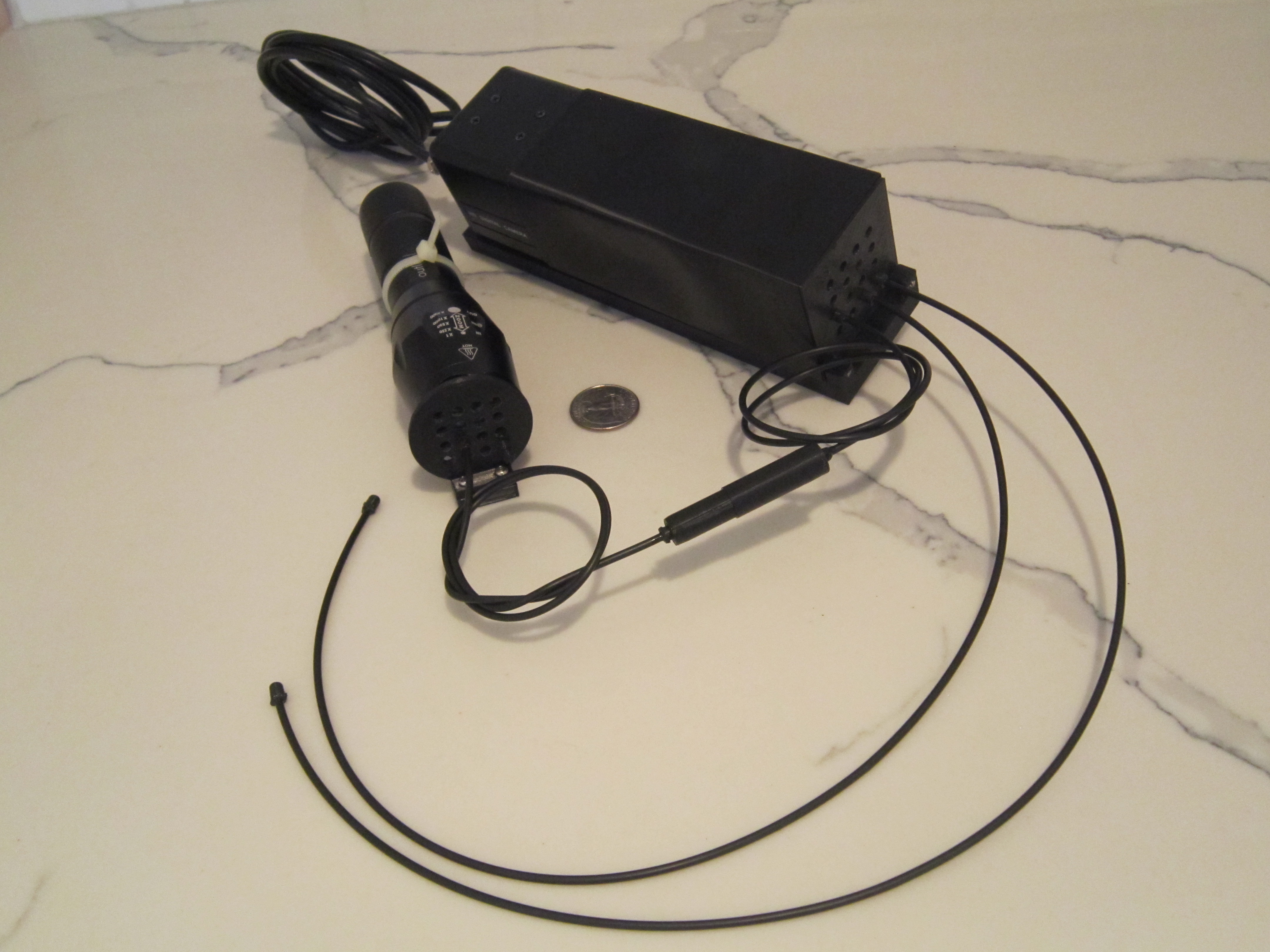
Attaching the fibers to the light module and camera module.
![]()
A sensor (fibergrid_sensor1.obj) is connected between the light and camera modules.
![]()
Two more fibers are added to the camera module.
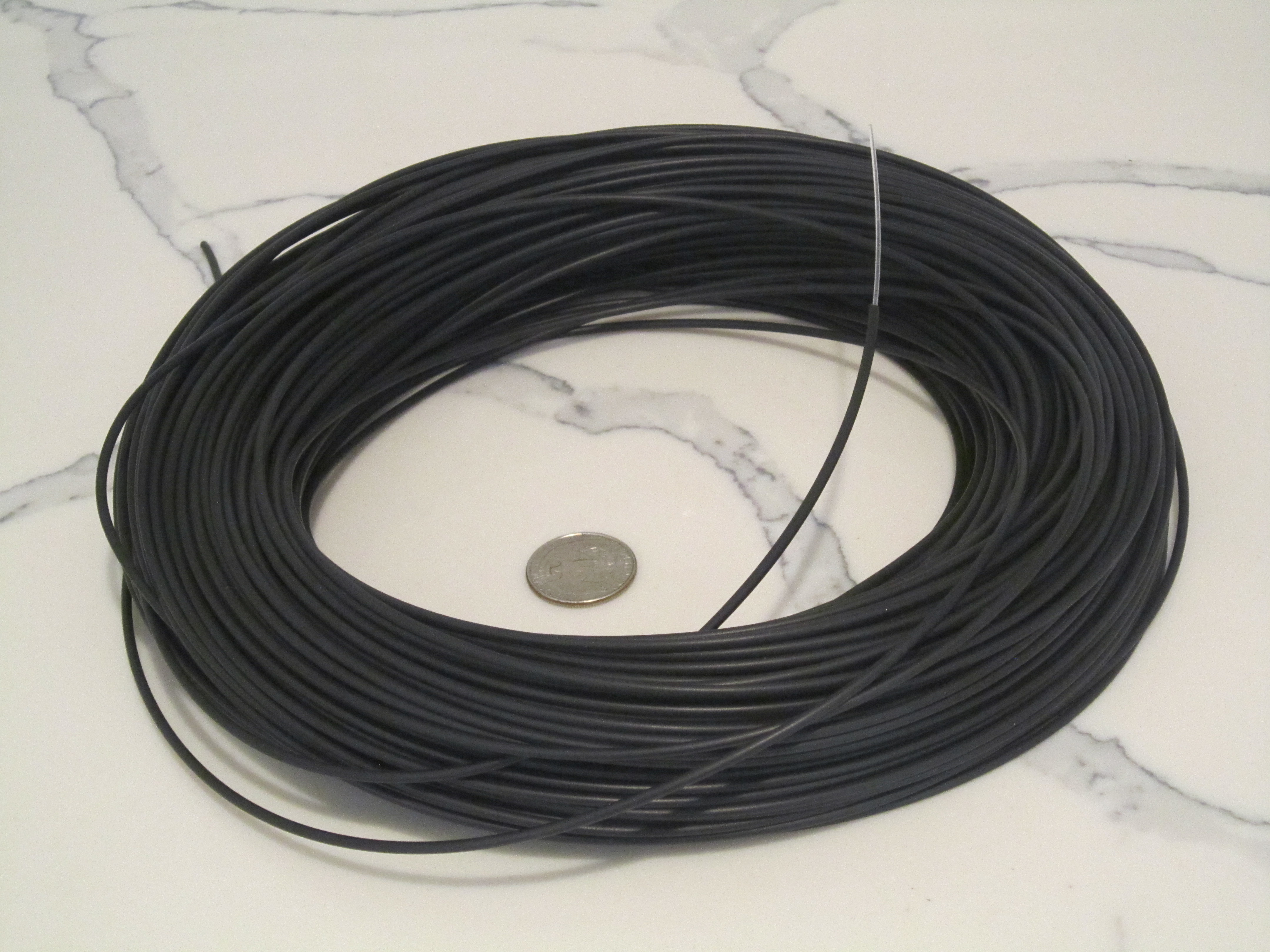
![]()
This is my spool of 1mm fiberoptic cable.
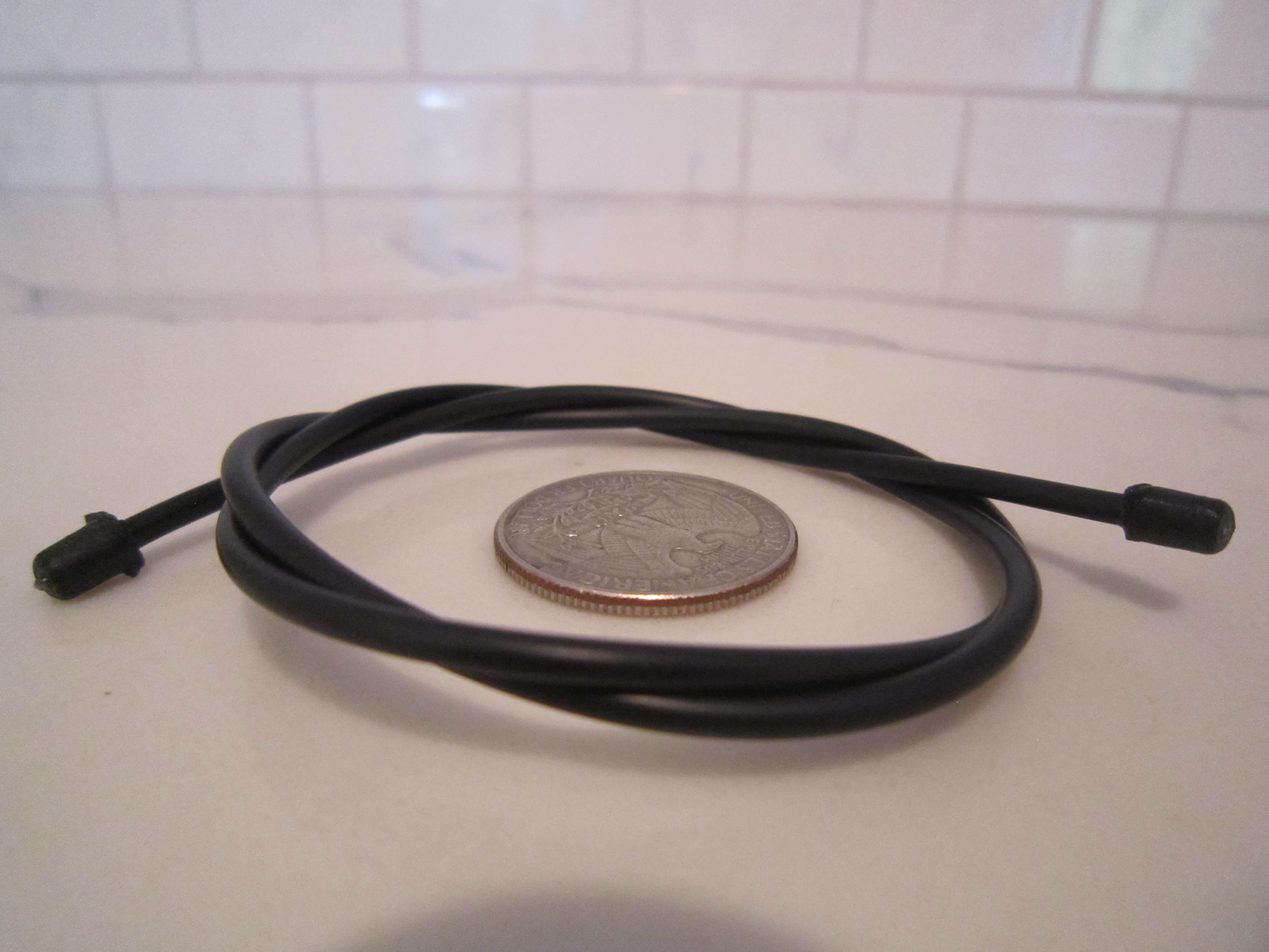
![]()
A length of the fiberoptic cable with two plugs glued to both ends. The fiber and the jacket are inserted into the plug with a drop of glue in it. After the glue sets, clip off the end of the fiber with scissors.
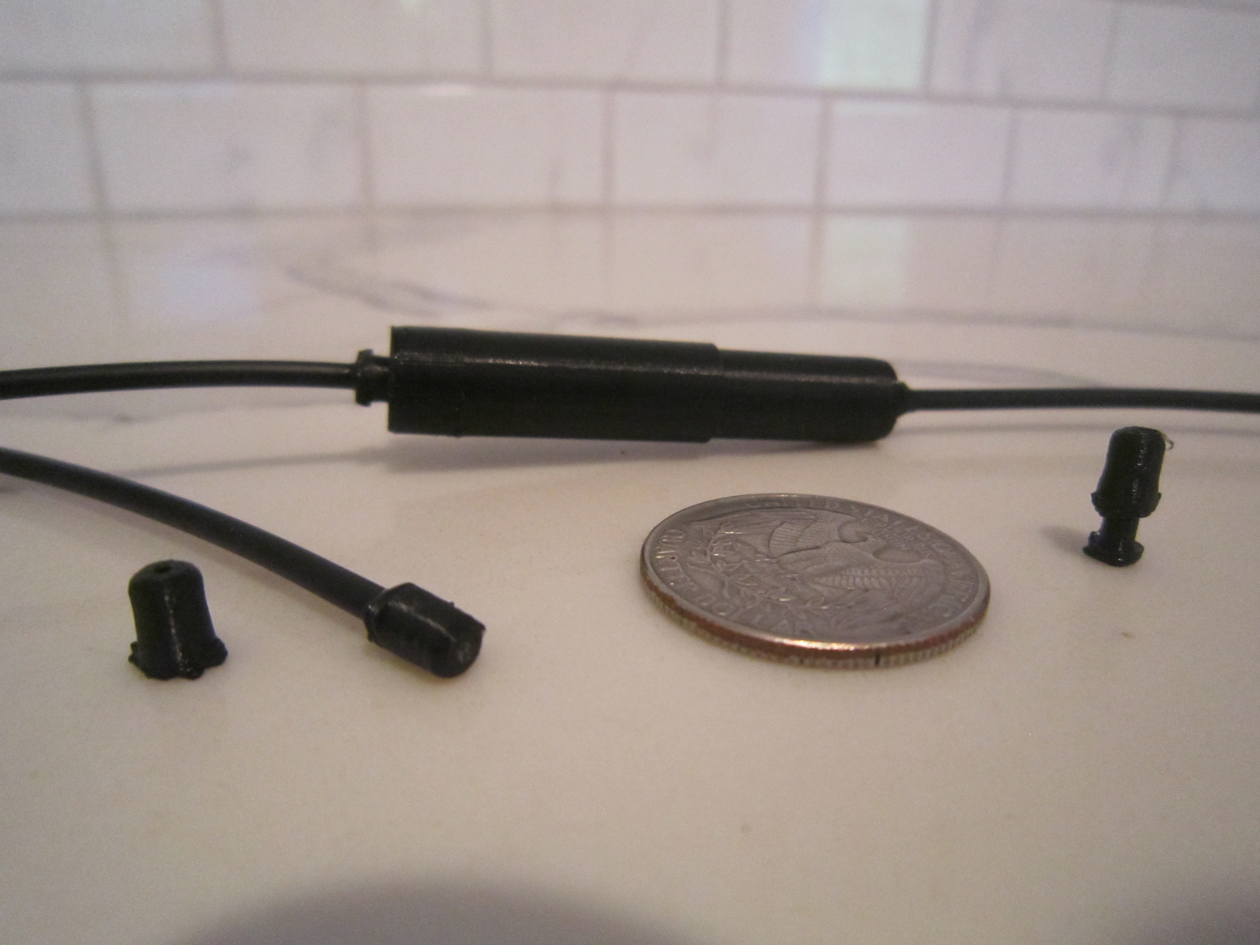
![]()
Plugs, and a sensor in the background.
![]()
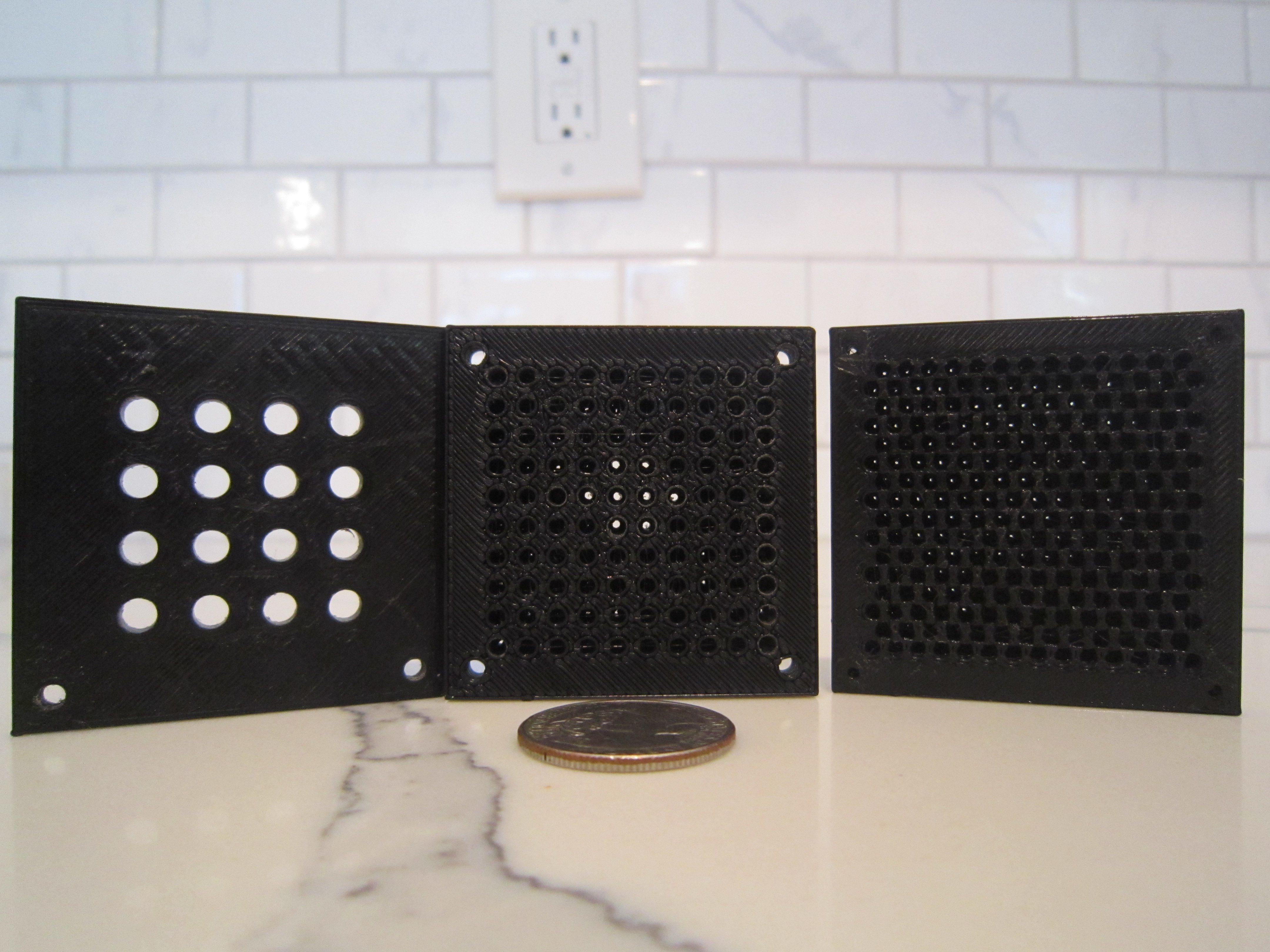
Choices for the grid: 16 connectors, 100 holes, 216 holes. In the two grids on the right the fibers have to be inserted and attached with glue directly.
-
3Alternative construction techniques
If you do not have a 3D printer, you can still play with this technology. Bunch-O-Baloons water baloon straws are perfect for putting up to 37 fibers in a grid. Fibers can be attached to individual straws with superglue. Bunch-O-Baloons can screw onto a neck of a plastic water bottle making it easy to attach to any container with a light or a camera. Glue the other end of the fibers directly into your sensors. Paint everything black or wrap with black tape.
![]()
As an alternative to Bunch-O-Baloons, drill holes with the diameter of your fiber through two sheets of black 3mm thick plastic. Enlarge the holes in one sheet to the thickness of your fiber jacket. Align the holes and glue the two sheets together. Secure fibers into the holes with glue. When the fiber is inserted it goes through both sheets of plastic, however the jacket will go in half way making a secure connection. -
4Troubleshooting
Plugin the camera into your computer and point the fibers towards the light. Start your favorite camera software. You should see bright dots on your computer screen. Nothing except fibers should allow light to enter the module. It is important that the fibers are fixed securely in place and do not move on the screen when you slightly twist or pull on them. If they shift or rotate, sensor readings will not be accurate.
-
5Assembling fibergrid_sensor1
Fibergrid_sensor1 folder in fibergrid_3Dmodels_v0.1.zip contains a cad file with models for two tubes that fit inside each other. There are also inserts for each tube. They have different diameters. Print two inserts for each tube (4 total).
Start by cutting two circles of polarized plastic the diameter of the tubes (9mm and 8mm?)
Slide an insert in the tube. place the plastic circle over it. Place another insert over that and push them all the way in. This way plastic gets sandwiched between the inserts across the tube.
Do the same for the other side.
Slide one tube in the other and connect the fibers to their ends.
Twisting the tubes should change the amount of light going through the sensor.
-
6Compensating for bends in fiber
Depending on your fiber, bending it might scatter light and change the sensor values. To compensate for this, bundle two fibers going to a sensor together. One fiber will be connected to a sensor and another directly to a light emitting fiber via a junction that dimms the light. This emitter fiber has to be bundled with an emitter fiber going to the sensor. Alternatively an LED can be placed directly inside the sensor and both fibers lit up by one LED. Decrease in light intensity due to physical deformation of the fiber can be compensated in software by adjusting the sensor value with respect to the second fiber value change.


Discussions
Become a Hackaday.io Member
Create an account to leave a comment. Already have an account? Log In.
Some of your instructions are fairly clear, but others are not at all! Maybe I'm just tired, but for example, I didn't understand these last instructions with the tubes and the polarized film, and I especially didn't understand the part about using 2 light fibers even though I understand what it's to accomplish. You just didn't explain it very well, and were not precise or consistent with your terms.
BTW, I'm very familiar with sensors, and inproving sensor signals and/or Common Mode Rejection techniques. I just didn't follow your words.
Good project, though. You should fix these problems. It's clear you put some thought into it.
Are you sure? yes | no