Blecky
-
Embiggen
09/17/2019 at 15:52 • 0 commentsThe holes on all through hole parts have been made bigger to account for slanted legs and bevels on the solder joints on the original board (so it sits relatively flushish to make soldering easier). Also added is optional zero crossing detection.
![]()
Once you are happy with the design, the best way to check for the fit is to print it out, cut any routed sections out and place it over the top:![]()
Make any small adjustments to the measurements until it fits square on. Then it's off the to board house for manufacture! -
Placing Components
08/27/2019 at 17:08 • 0 commentsWhen placing components, note that the top layer of the board is the "bottom" of the main board, so we can put things anywhere on the top, and the bottom of our board will sit flush to the original board.
To get the thermocouples re-integrated, we have to add an additional section to the board. An additional board section near the existing thermocouple connectors has been extended to account for this. Here's a first cut:
![]()
Some notes about the existing board:
- LEDs are driven by the outputs, so there's no need to connect to these.
- Pullups are already on the buttons, so these aren't required again.
- There is a Dallas DS18B20 one wire through hole sensor which sits above the board. It is unknown what the actual purpose of this is, but I presume it is for cold junction compensation. But since it sits way above the board and is relatively far away from the thermocouple connectors, it's not really going to be accurate at all. If it is used as a generic temp sensor, then we can use the MAX31855 to get this instead and disregard the connection to it.
- There's a lot of other redundant connections, such as an unpopulated EEPROM connection.
-
MMmmmmm Swiss Cheese Board
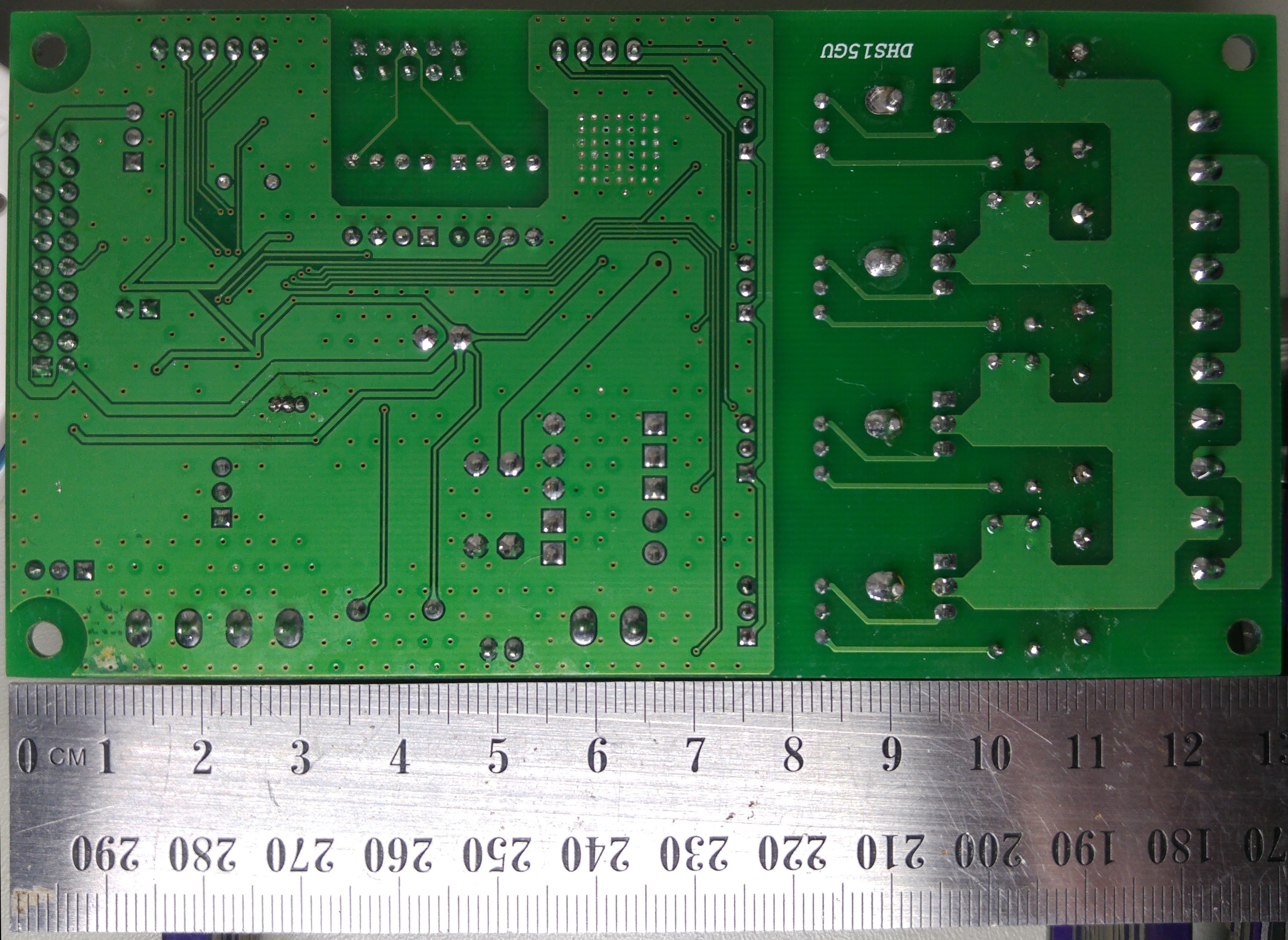
08/27/2019 at 16:38 • 0 commentsSo you do a few measurements of the board and you get something like this:
![]()
The headers on there join up with the through hole parts that were standard 2.54mm pitch. The great thing about these is that there is one reference point in which to take the measurement from (pin 1). You could make the holes a bit bigger for these, to get around the solder joint, but in this instance the board doesn't have to be perfectly flush and I might just clean those joints up a bit before soldering anyway.
The other holes required were non standard pitch, so you can link these with vias. The via size just needs to be a bit bigger than the original solder joint/blob.
As for the rest of the solder joints, you can just route in cutouts where these are. These don't need to be too precise, just give enough clearance for the joints.
When using ImageJ, you can draw shapes around parts, then right click the yellow shape and click Draw, which leaves a white mark where you drew the shape. This is handy when using the measurement line. Also Ctrl+m is the shortcut for taking a measurement, which also shows instantly in the results window.
Also don't stress about the thin PCB section at the bottom, the PCB needs to grow about 10mm on the bottom edge to allow for a re-routing of the thermocouple headers, as the original ones have one pin shorted to ground (which isn't suitable for the thermocouple IC that's going to be used).
-
Does It Measure Up?
08/26/2019 at 12:15 • 0 commentsHow are we going to make a mod PCB without the original design files? Well here's my trick for doing so. There's possibly a better way, but this is a super simple method of getting things pretty close.
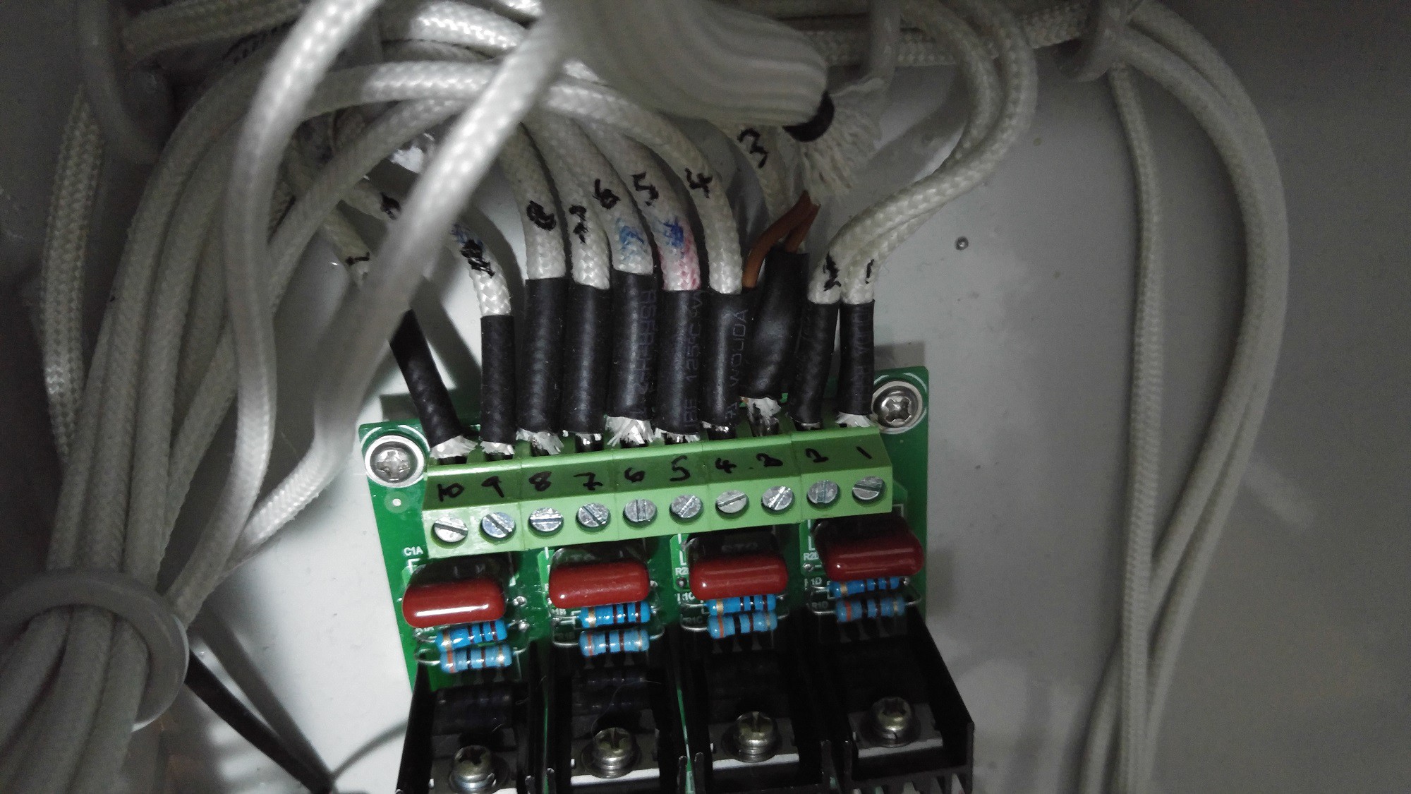
Firstly, make sure to label all the cables so things go back the way they should be before removing the PCB:
![]()
Take some images of the PCB with a ruler for reference as "square on" as possible (try to minimise rotation and perspective angles). It doesn't have to be perfect as we will confirm measurements later in development, with a printout of the final design to see if things line up. One tip is to use a long focal length and crop the image, but this isn't 100% necessary unless you have some really tight tolerances (through hole is far from tight):
![]()
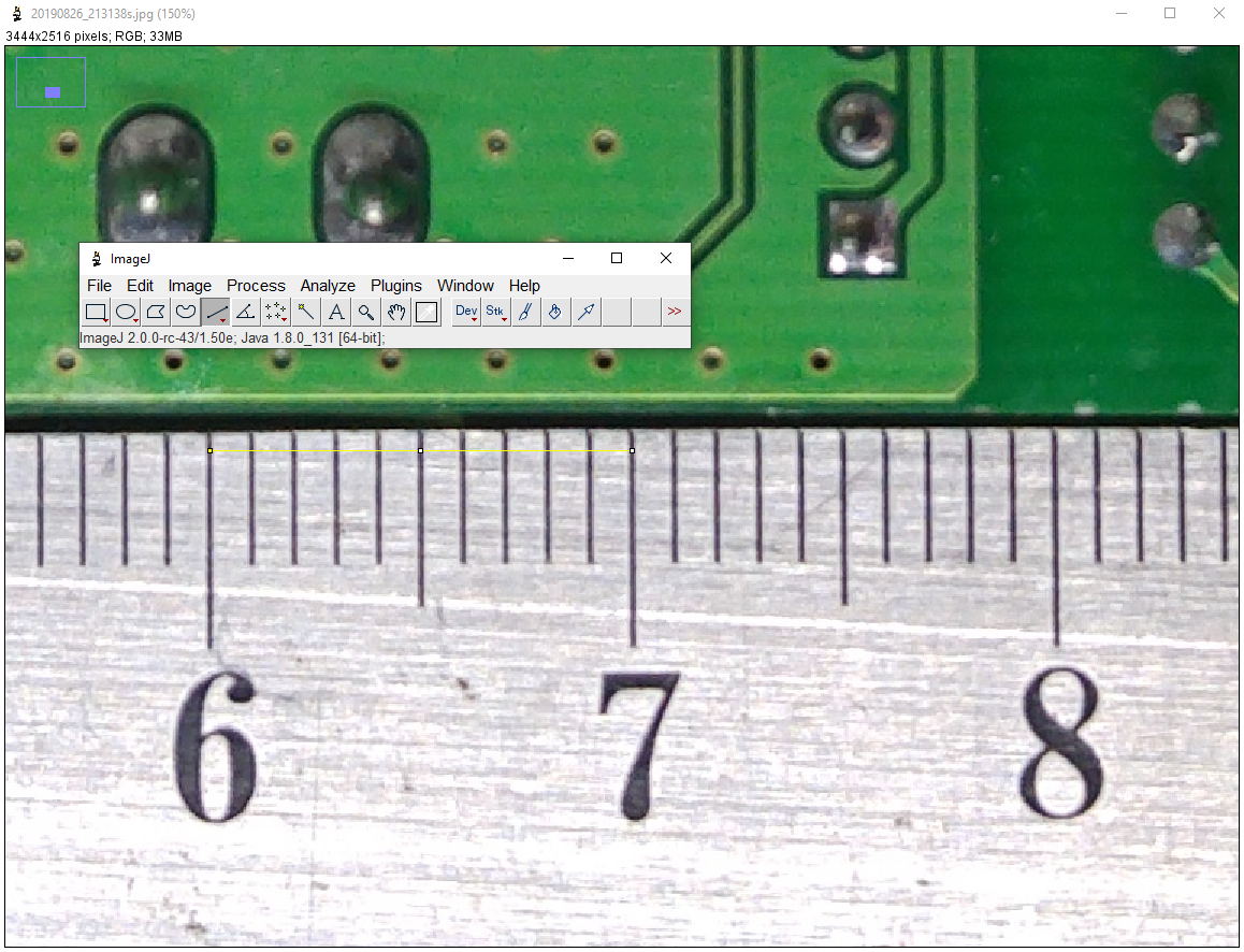
Now grab a tool called ImageJ and open the image in it. Select the straight line tool and measure between two known points on the ruler:
![]()
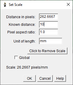
Now goto Analyze>Set Scale...:
![]()
Change the known distance value (don't touch anything else except to optionally change the unit of length field for your reference) with the distance you have, in this case it's 10mm and we will be using a mm scale for the rest of our measurements, so set it to 10. This can be any scale you like (I could use 1 cm here too in which case you put 1 in the known distance). Just remember to use the same scale throughout when taking measurements.
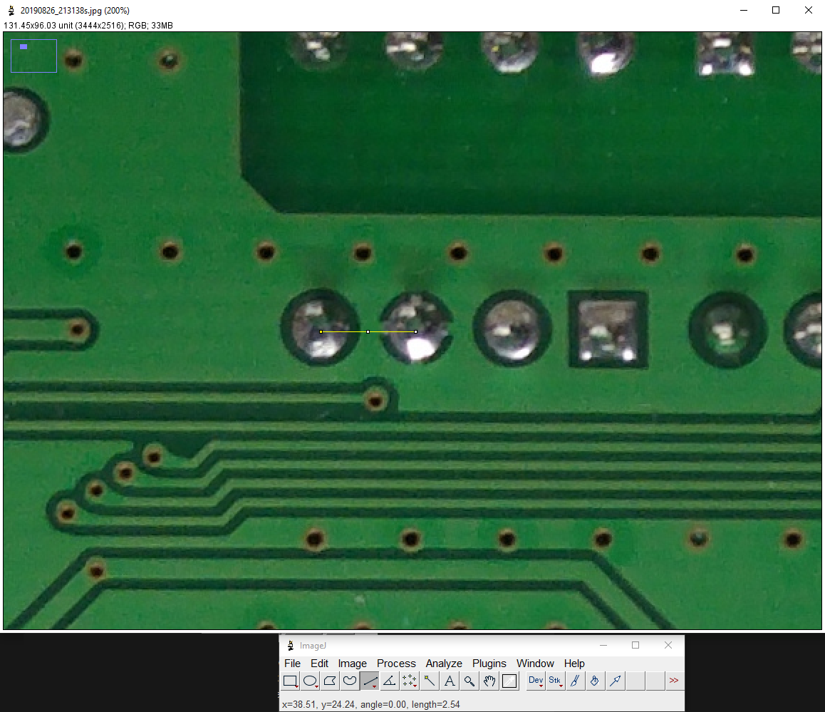
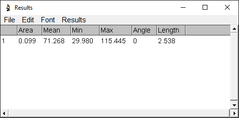
Now go ahead and use any of the tools to take measurements (check the length value in the status bar for the measurement):
![]()
You can also check the Analyze>Measure tool to see more accurate measurements (the distance between those two pins is 2.54mm which sounds spot on for this part):
![]()
Now onto creating a PCB with hundreds of measurements. I usually sketch the board positions out first in CAD so you can import a DXF file into your EDA tool, but pen and paper work just fine too.
-
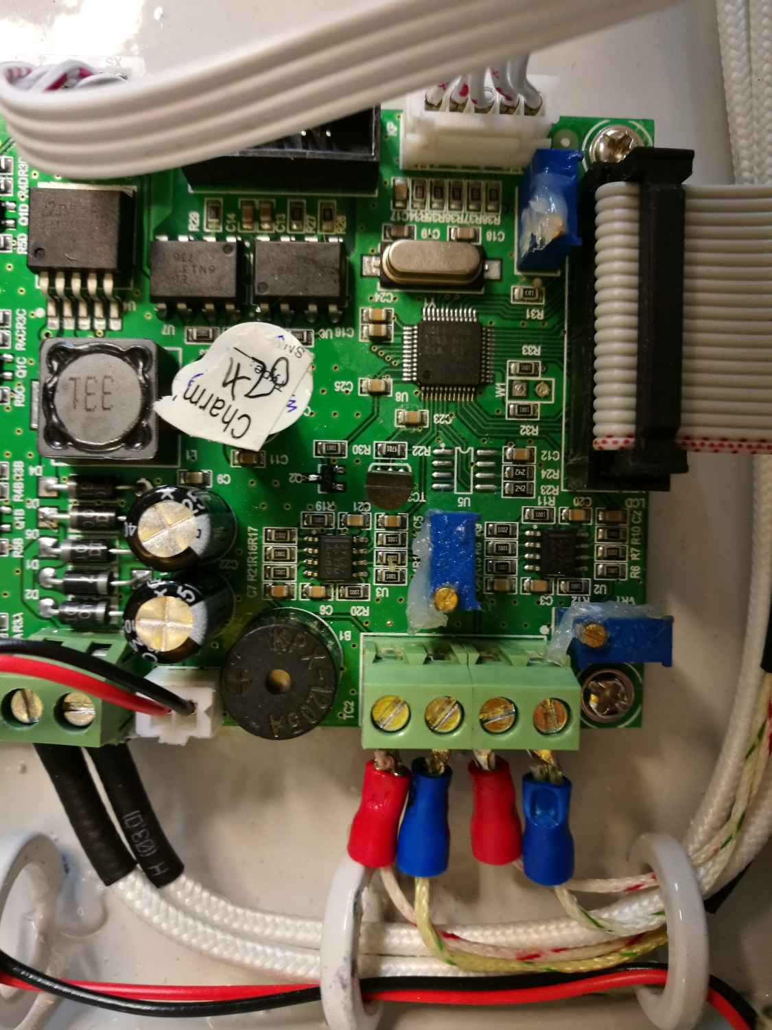
What's Going to Happen?
08/25/2019 at 15:11 • 0 commentsIf you've followed my other project, you'll find that this machine lacks some very simple interface features. Also mentioned is the oven's use of the Cypress/Fujitsu CY96F613, an obsolete, 16bit microcontroller with an unobtainable build chain.
![]()
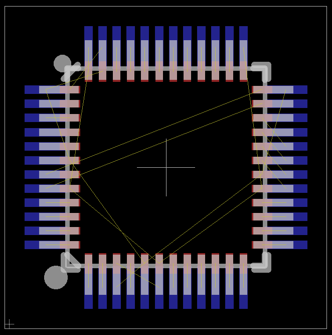
To overcome this, I'm going to completely replace this microcontroller with a new one. The existing microcontroller has a TQFP footprint in a pretty tight space. I did look at creating an adapter to replace the existing one with a new SAMC21 (5V capable) VQFN variant:
![]()
But, this still leaves us with the poor thermocouple interface to contend with, could be quite tricky to solder in place and would be difficult to initially program the bootloader/reprogram if something goes wrong.
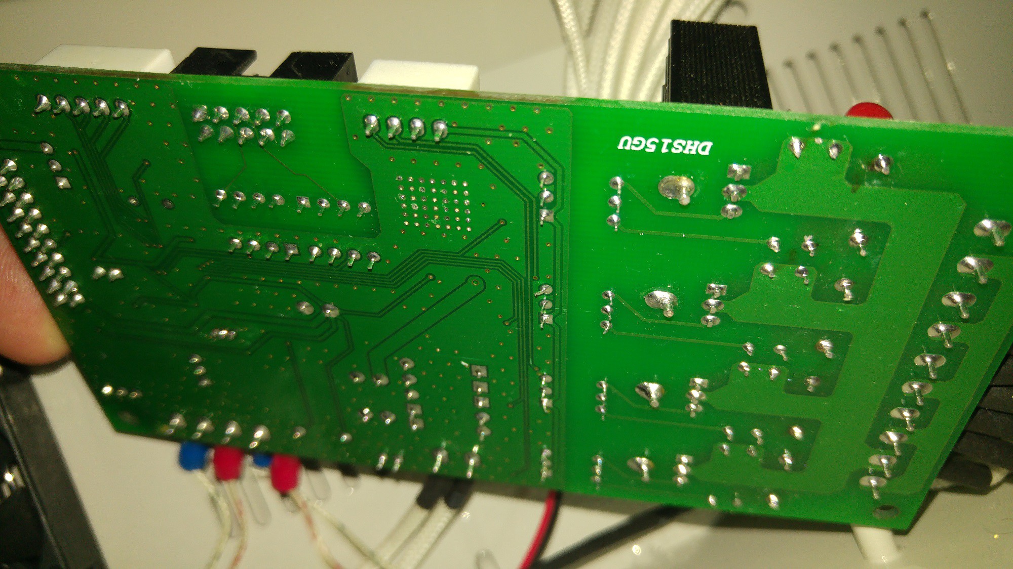
So instead, we look underneath:
![]()
All of the (low voltage) components we need to connect to are through hole devices. So we can easily create a mod board that connects up to all these pins, completely populated with the SAMC21 (and ICSP interface) and a couple of MAX31855's to replace the existing thermocouple circuit. In addition to this, we'll be piggybacking on the existing optocoupled serial interface, which can be broken out into a USB interface for programming and debug.
This all removes the need to create a completely new, full sized board as all the other components are already there.
Easy peasy!
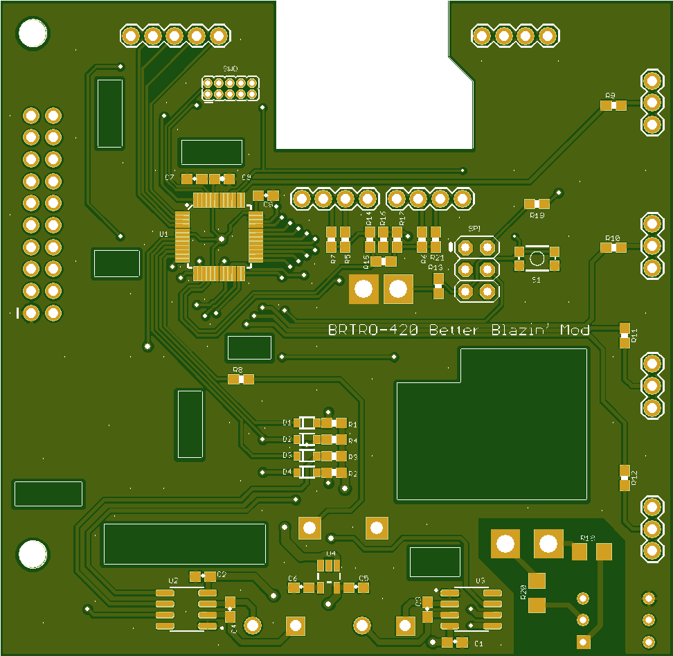
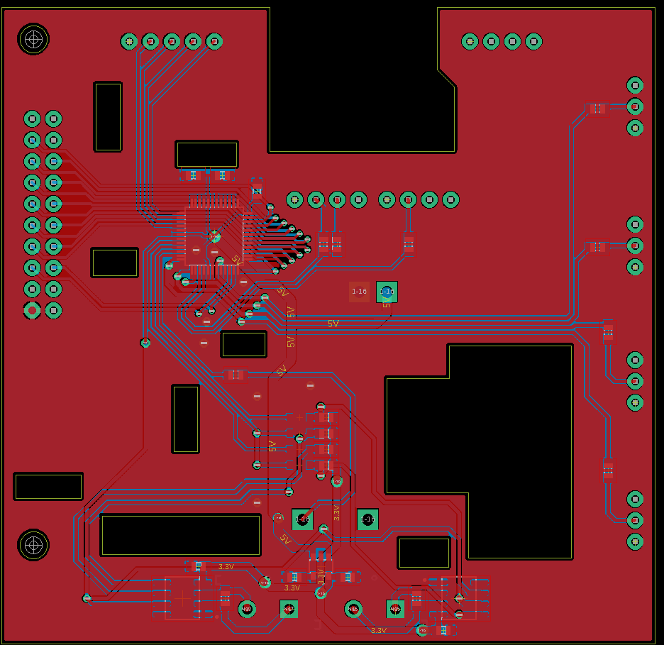
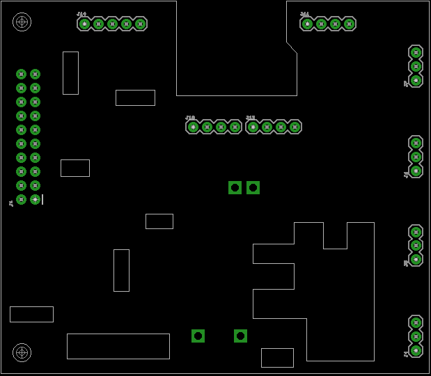
BRTRO-420 Better Blazin' Mod
Modify the BRTRO-420 reflow oven to have an Arduino based reflow firmware, serial interface and cold junction compensation.