 igorfonseca83
-
1Tools and Materials
The following tools and materials were used in this project:
Tools and materials:
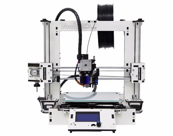
- 3D printer (link / link / link). It was used for printing the case where the electronics are encloused.
![]()
![]()
- Solder iron and wire. Some of the components (ESP32 Firebeetle and HX711, for instance) doesn't come with soldered terminals. I needed to solder some wires or pins in order to connect those devices.
- Shrinking tube. l also had to solder the wires of each load cell. A piece of shrinking tube might be used for a better isolation of the conductors.
- Screwdriver. The structure is mounted using some screws. A set of screwdrivers was used.
- M2x6mm Bolts. They were used for mounting the electronics inside the case.
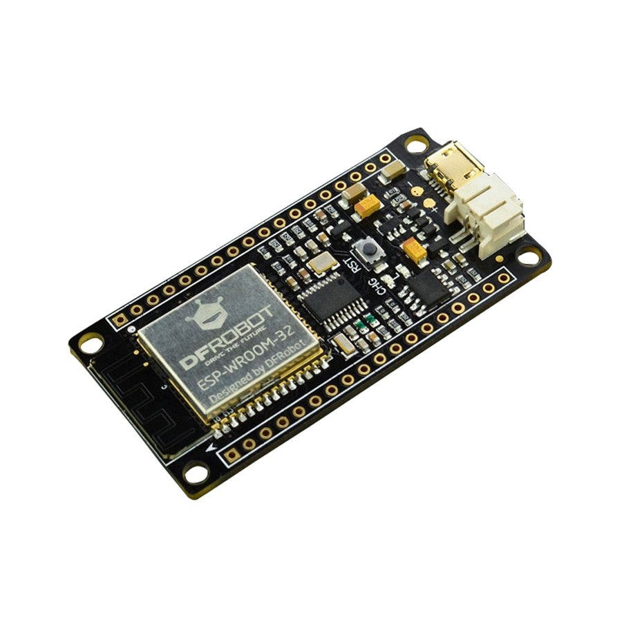
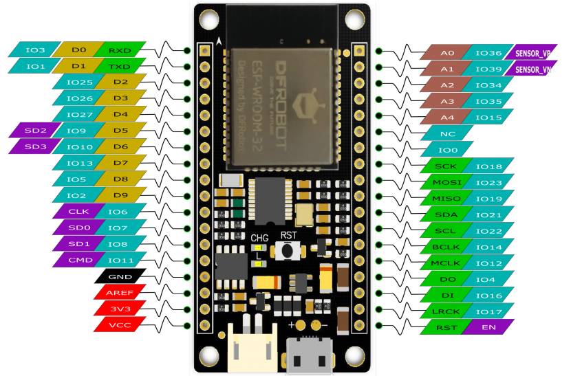
- FireBeetle ESP32 dev board. It's really easy to use and program using Arduino IDE. It has built-in Wi-Fi module, so you can use it in a variaty of projects. You can also use other ESP8266 based bords (link / link / link) if you wish.
![]()
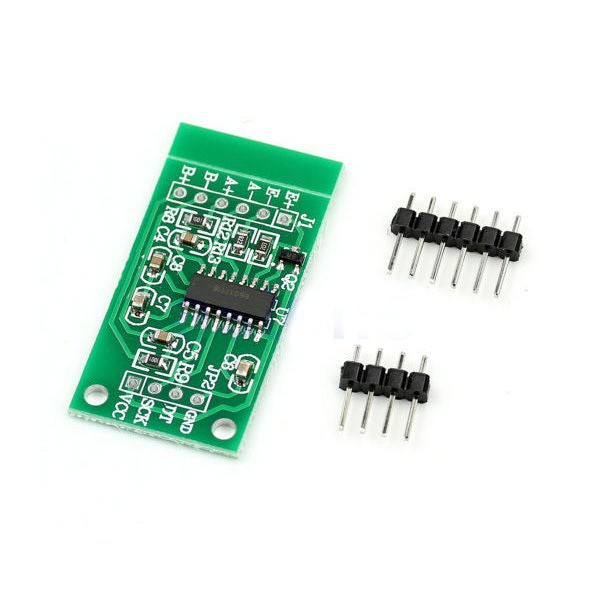
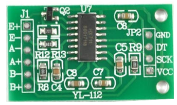
- HX711 module (link / link / link). This works as a load cell amplifier. Four strain gauge load cells are connected to this module, and it communicates on a serial communication with the microcontroller.
![]()
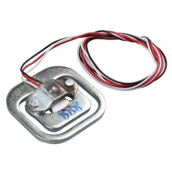
- 50kg load cell (x4); (link / link / link). They are used to measure the weight. Four of them were used for a maximum weight of 200kg.
![]()
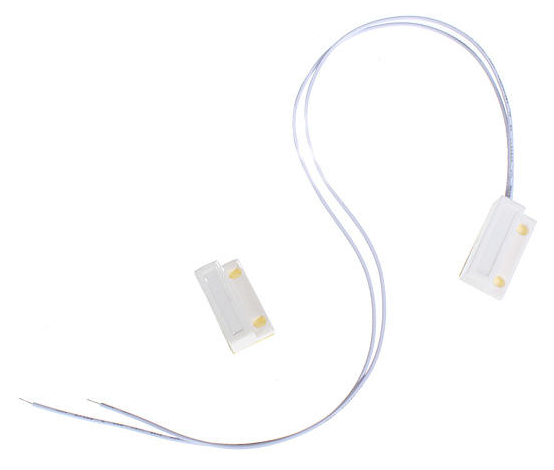
- Magnetic door sensor (link / link / link). It consists in a magnectic switch, which was used to detect that the litter box is opened.
![]()
- Micro USB cable;
- 6 female-female jumper wires;
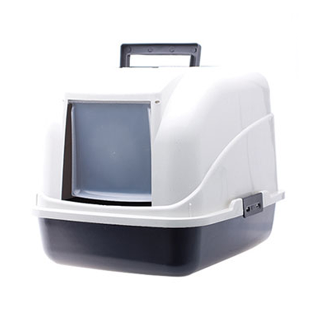
- Cat litter box.
![]()
The links described above are only a suggestion of where you can find the items used in this tutorial (and support my future hacks). Feel free to search for them elsewhere and buy at your favourite store.
I used a FireBeetle ESP32 dev board, which was kindly supplied by DFRobot.
Did you know you can buy a Creality Ender 3 3Dprinter for only $168.99? Get yours! https://rebrand.ly/3Dprinter-BG
-
2Setup FireBeetle ESP32 on Arduino IDE
![]()
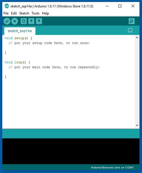
For this project I used Arduino IDE for programming my ESP32 module. It's the easiest way if you've already used an Arduino before, and you won't need to learn a new programming language, like Python or Lua for instance.
If you've never done this before, first you'll have to add ESP32 board support to the Arduino software.
1. Download and install Arduino IDE latest version
You can find the latest version for Windows, Linux or MAC OSX on Arduino's website: https://www.arduino.cc/en/main/software
Download it for free, install it on your computer and launch it.
2. Adding ESP32 board
Arduino IDE already comes with support to a lot of different boards: Arduino Nano, Mine, Uno, Mega, Yún, etc. Unfortunatly ESP32 isn't by default among those suported development boards. So in order to upload your codes to a ESP32 base board, you'll have to add its properties to Arduino's software first.
- Navigate to File > Preferences;
- Add the following URL to Additional Boards Manager textbox (the one on the bottom of the Preferences window):
https://git.oschina.net/dfrobot/FireBeetle-ESP32/raw/master/package_esp32_index.json
- If the text box wasn't blank, it means had already add other boards before on Arduino IDE before. Add a comma at the end of the previous URL and the one above.
- Hit "Ok" button and close the Preferences Window.
- Navigate for Tools > Board > Boards Manager for adding your ESP32 board.
- Type "FireBeetle-ESP32" on the search text box, select "FireBeetle-ESP32 Mainboard by DFRobot DFRDuino" and install it.
Now your Arduino IDE will be ready to work with ESP32 FireBeetle board.
Plug the microUSB cable on the ESP32 and on your computer. It will automatically install Windows communication driver. If it fails to install the driver, download the following file and manually install the driver for the newly connected device.
https://git.oschina.net/dfrobot/FireBeetle-ESP32/raw/master/FireBeetle-ESP32.inf
If you wish to use an alternative ESP32 based board, add the appropriate board.
3. Adding the libraries
The following libraries will be used for our Arduino code. Download the following libraries:
- Thingspeak library: https://github.com/mathworks/thingspeak-arduino
- HX711 library: https://github.com/bogde/HX711
Navigate to Sketch-> Include Library -> Manage Libraries... on your Arduino IDE and add the libraries above.
............
Now that your dev environment is ready, let's move on to the next step!
-
3Wiring Up - HX711, Load Cells, Reed Switch and ESP32
This project used the following electronic components:
- ESP32 Firebeetle development board: This board has an Expressif microcontroller and is the component responsible for reading variables, handling and sending data to the cloud using a WiFi connection. It is in this device that the project code runs.
![]()
- Load Sensors: component responsible for measuring the force, converting the pressure applied on the device into an electrical signal.
- Amplifier HX711: circuit responsible for the amplification of the electric signal generated by the charge cells and digital analogue conversion of sina. The signal generated by the load cells has a very restricted amplitude (signal in mV). This circuit amplifies this signal and performs the conversion of the analog signal to digital, delivering the converted signal to the microcontroller.
![]()
- Door sensor switch: consists of a switch that is normally closed in the absence of a magnetic field. When applied a magnetic field in its proximity, the switch closes an internal contact, allowing the conduction of electric current. In this project, a switch of this type was used to identify whether or not the top of the litter box was opened. A magnet has been attached to the top cover, while the switch is attached to the controlled and fixed on the bottom of the box. When that cover is closed, the magnet and key will be aligned and close together, keeping the switch closed. When the two parts are separated, the magnet will move away from the switch and the circuit will open.
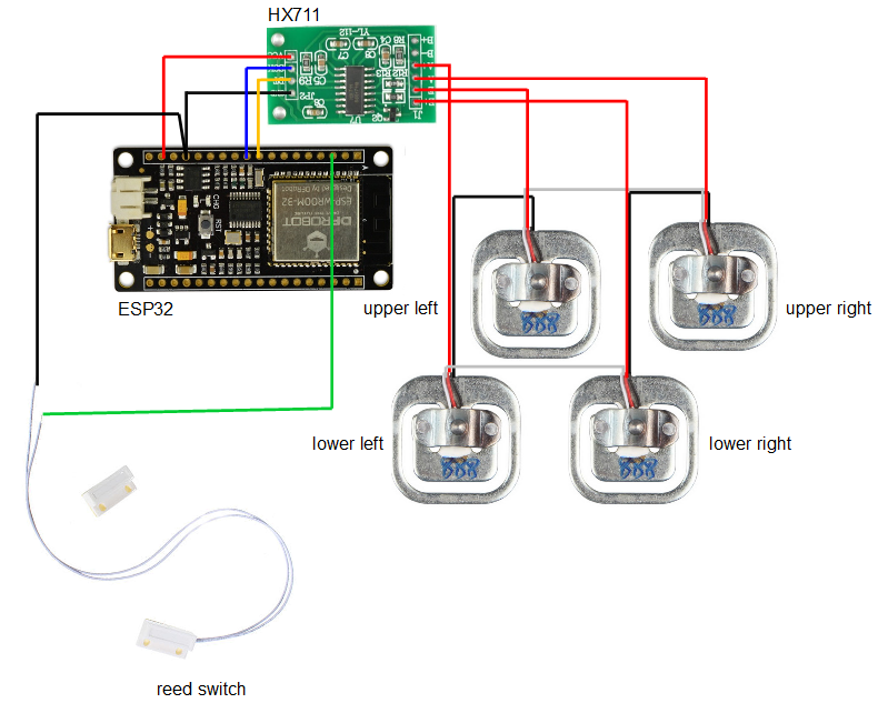
Each device was connected according to the schematics.
![]()
HX711 - input:
- Upper left load cell signal (red wire) => HX711 E- pin
- Lower left load cell signal (red wire) => HX711 A+ pin
- Upper right load cell signal (red wire) => HX711 A- pin
- Lower right load cell signal (red wire) => HX711 E+ pin
HX711- output:
- HX711 Vcc pin => ESP32 3.3V pin
- HX711 GND pin => ESP32 GND pin
- HX711 SCK pin => ESP32 GPIO 2 (pin D9)
- HX711 DT pin => ESP32 GPIO 5 (pin D8)
Door sensor:
- Reed switch (terminal 1) => ESP32 GND pin
- Reed switch (terminal 2) => ESP32 GPIO 25 (pin D2)
When everything is wired up, plug a USB cabe on the ESP32 and get ready for uploading the code.
-
4Thingspeak Setup
![]()
There are several cloud data storage services for use with the internet of things. They allow communication between your microcontroller and the network, allowing you to send and receive all kinds of data. You can see some of the projects I've developed using Adafruit.io, for example:
https://hackaday.io/project/159086-diy-wi-fi-smart-scale-with-esp8266
https://hackaday.io/project/28284-iot-air-freshenerThingspeak is another such service. It is really easy to use, allowed monitoring of various information.
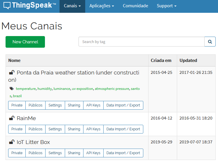
1. Create your account: first you must create your account at https://thingspeak.com/.
2. Create your channel: Once your account is created, you can create a channel where your data will be stored. Click on "New channel" and enter the name of your channel In my case I created a channel called "IoT Litter Box".
![]()
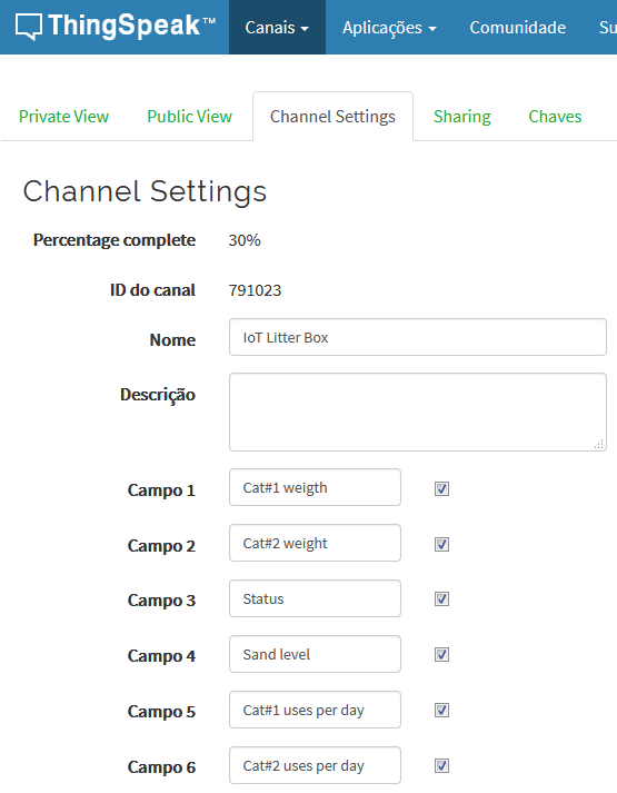
3. Set the fields of your channel: each channel can have up to 8 fields. Each field is equivalent to a variable that will be stored on your channel. In my project, 6 channels were used:
- Cat Weight #1
- Cat Weight #2
- Status
- Sand level
- Uses per day of cat #1
- Uses per day of cat #2
![]()
4. Write down your writing key: click the "Keys" option and copy your write key. You will need this information later in your Arduino code.
![]()
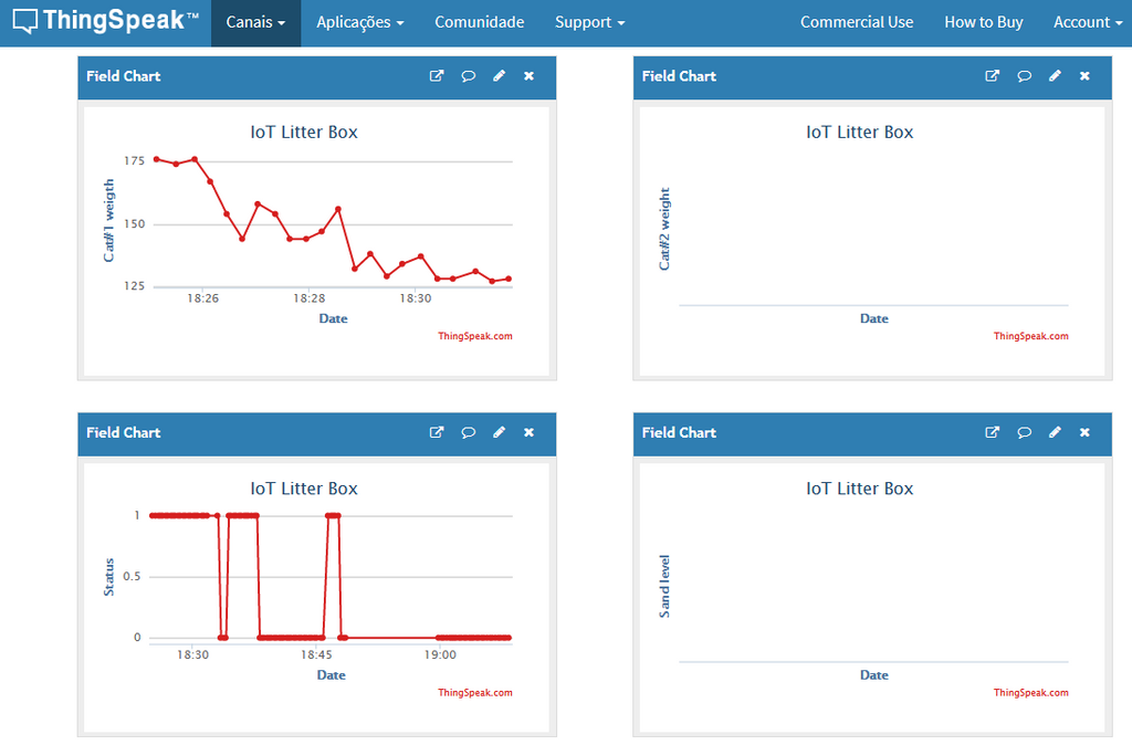
And it's ready! Your channel will be set up to start receiving data from your controller. You can see the data beginning to arrive in the Public view tab (if your channel is configured as public) or Private view. You can create specific views for public and private modes.
-
5Arduino Code
![]()
The code idea is as follows: 1 - The controller must be initially calibrated to know the empty box weight and adjust the calibration factor. The information on how to calibrate is presented at the end of this tutorial. This information will be stored in the controller memory and is not expected to change over time. This value will be used in the future to allow the calculation of the volume of sand and individual weight of the cats.
2 - Whenever the top of the box is opened, the controller understands that the box has gone into maintenance (cleaning) and should stop monitoring the box weight measurement. In that period, someone should be tossing sand (adding or removing sand, poop, etc.), and there should be fluctuations in box weight.
3 - As soon as the box is closed, the controller should wait some time for stabilization and re-check the weight. The first measurement performed should be stored in the controller memory as the weight of the box + sand. This value will be subtracted from future measurements to allow the calculation of the weight of the cats discounted from the weight of the box and its sand content.
4 - By subtracting the measured weight (in the absence of a cat inside the box) from the empty box weight (stored in the controller during its calibration), it is possible to determine the volume of sand in the box. This value is expected to decrease over time whenever the litter box is cleaned. You can set alarm limits to alert when the sand level in the bin is too low, indicating the need for general cleaning and sand replacement. The sand volume in the box will be sent to the cloud and you can generate alerts.
5 - Whenever the controller senses a significant increase in the weight of the box with the top cover closed, you will understand that some cat must have come in to make your needs. After stabilizing the measurement (understanding that the cat has stopped moving to make its needs), the controller will store the measured average weight. The value will be compared with expected maximum and minimum values for each of the cats (assuming more than one cat should use the box) in order to determine which cat has entered the box. The information on the weight of the cat and the count of times the cat used the box on the day will be updated and sent to the cloud.
6 - Periodically the controller check the time from a server. When detecting the beginning of a new day the counter of times that each cat used the box will be reset.
The following statements should be updated according to your case:
- myChannelNumber = Thingspeak channel number
- apiKey = ThingSpeak API key
- ssid = ssid of WiFi network
- pass = WiFi network password
- weightbox = weight indicated for the empty box
- cat1MinWeight = minimum weight of cat # 1
- cat1MaxWeight = maximum weight of cat # 1
- cat2MinWeight = minimum weight of cat # 2
-
63D Modeling
3D printing was used to make some of the parts in this project. Of course the litter box itself was bought in a normal pet shop. However, some custom parts had to be designed and printed to allow the electronics to be added to the litter box. All parts were designed using Fusion360 CAD software.
![]()
The following parts were designed:
- Supports for the load sensors: the load sensors are embedded inside four supports on the box feet. Such brackets allow the installation / removal of the sensors..
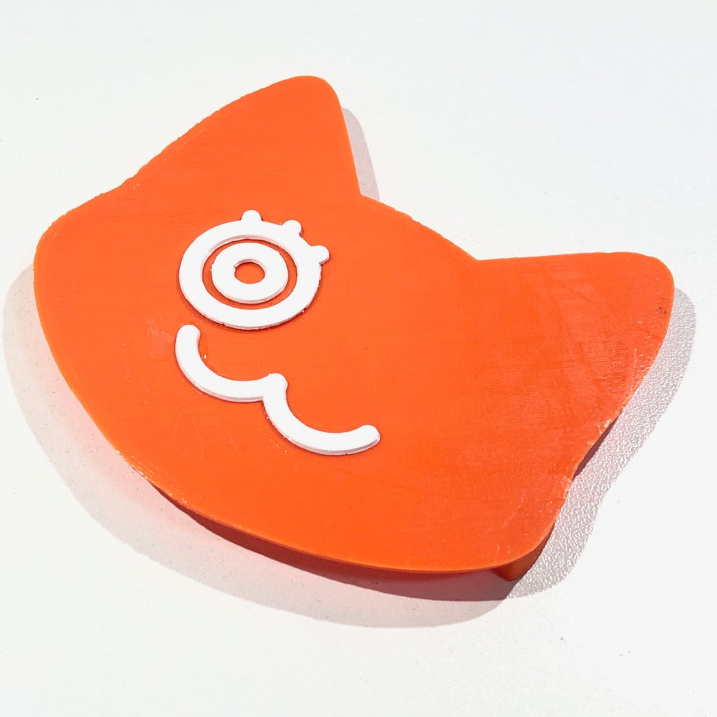
- Case: the case protects the electronic components from physical contact. The case is designed to be installed in the box using double-sided adhesive tape, thus allowing the case to be subsequently removed (for cleaning the case, for example).
![]()
- Case cover: allows frontal closure of the case, protecting electronic components.
![]()
![]()
-
73D Printing
![]()
You can download all the stl files on the following websites:
https://www.thingiverse.com/thing:3737074
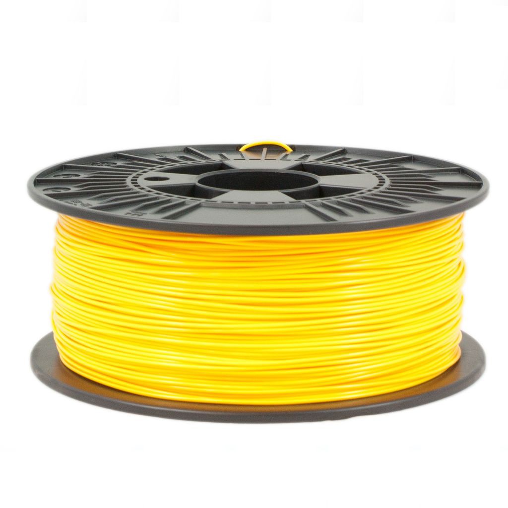
I printed the whole structure in PLA, usign two different colors. The whole print took me around 5h, using 0.2 mm resolution and 10% infill. No supports needed. This is a experimental prototype. Notice that it was designed for a given ESP32 dev board model (the ESP32 Firebeetle).
Sensor pad:
![]()
![]()
![]()
Case:
![]()
![]()
![]()
Front cover:
![]()
![]()
![]()
If you don't have a 3D printer, here are some things you can do:
- Ask a friend to print it for you;
- Find a hacker/maker space nearby. The parts used in this model can be printed quickly. Some hacker/maker spaces will only charge your for the materials used;
- Buy your own 3D printer. You can find the Creality Ender 3 for only $169.99! Get yours at https://rebrand.ly/3Dprinter-GB
- Improvise! You can try to assemble a structure without 3D printed parts.
-
8Assembling the Litter Box
Once the parts are printed, it's time to assemble!
1 - Solder the terminals of the HX711 module to the ESP32 using some jumpers according to the schematic previously presented;
2 - Solder a pin bar (male type) on the HX711 for later connection of the load cells;
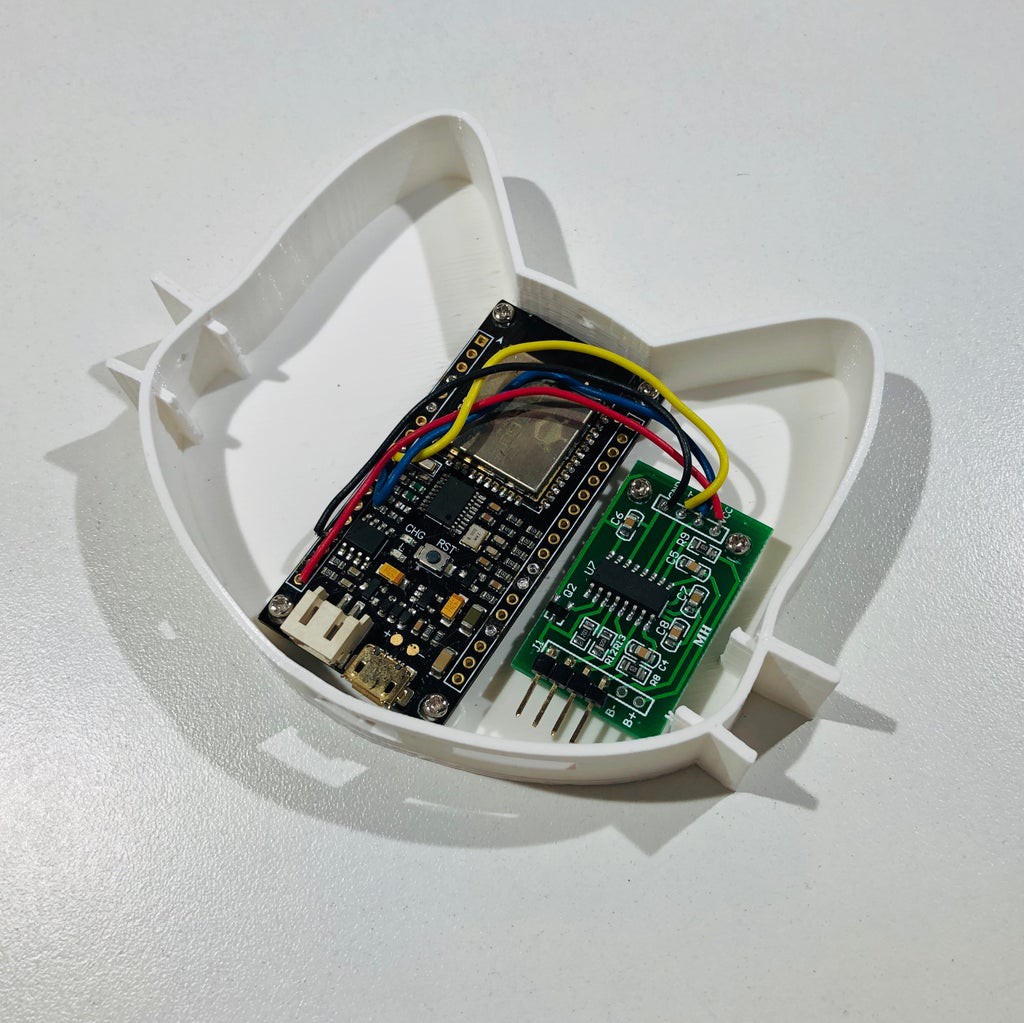
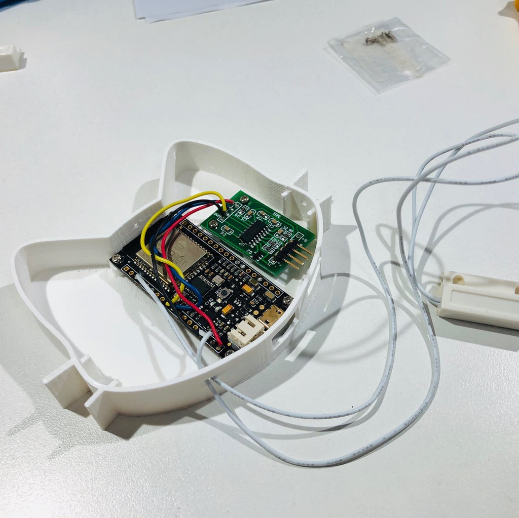
3 - Install the ESP32 and HX711 in the case using 6 M2x6mm screws;
![]()
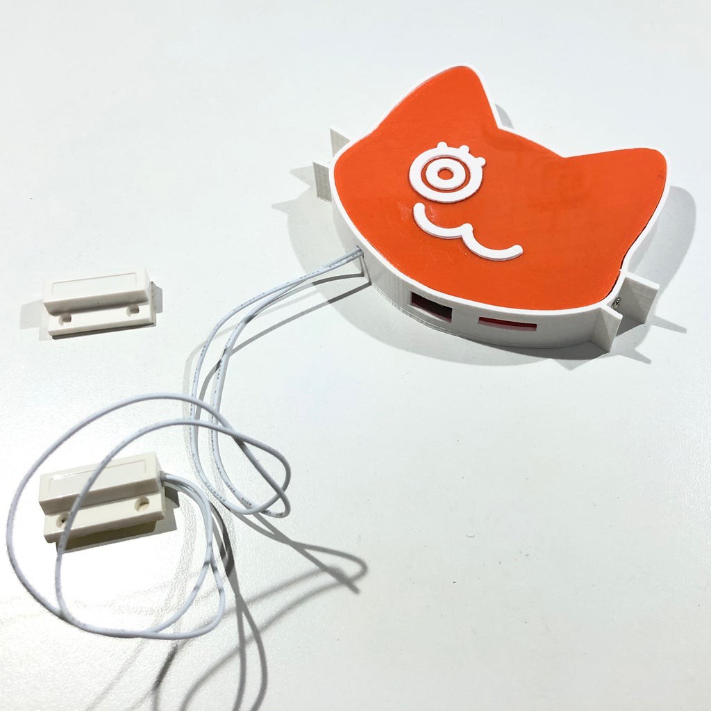
4 - Thread the reed switch wires through the bottom hole of the case. Solder the reed switch terminals according to the schematic above;
![]()
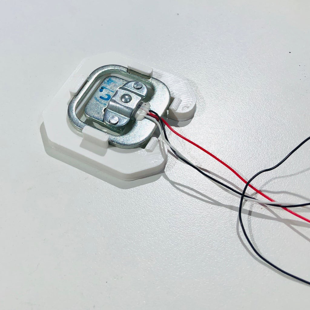
5 - Fit the load cells inside the supports printed in 3D;
![]()
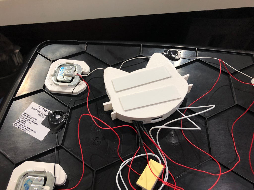
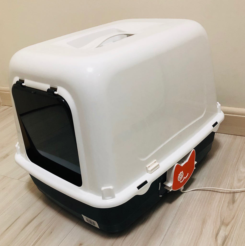
6 - Apply double-sided tape to the back of the case and glue to the side of the litter box;
![]()
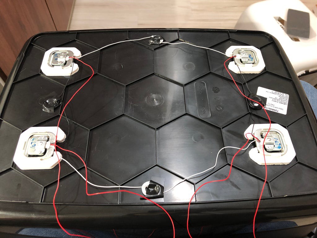
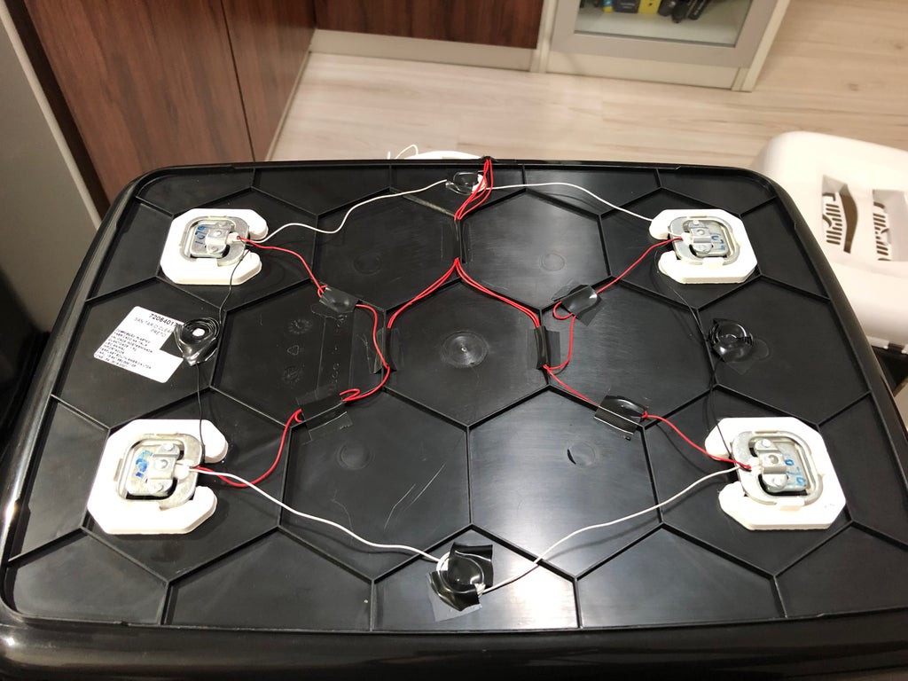
7 - Glue the load cells to the bottom of the litter box;
![]()
8 - Solder the wires of the load cells according to the schematic presented above. Solder a female connector on the red wire of each cell to allow its connection to the pin bar on the HX711;
9 - Arrange the wires. Use insulation tape to stick them to the box;
![]()
10 - Collect the load cells to the HX711 module according to the schematic previously presented;
11 - Install the front cover. Use three M2 x 6mm screws to secure the cover;
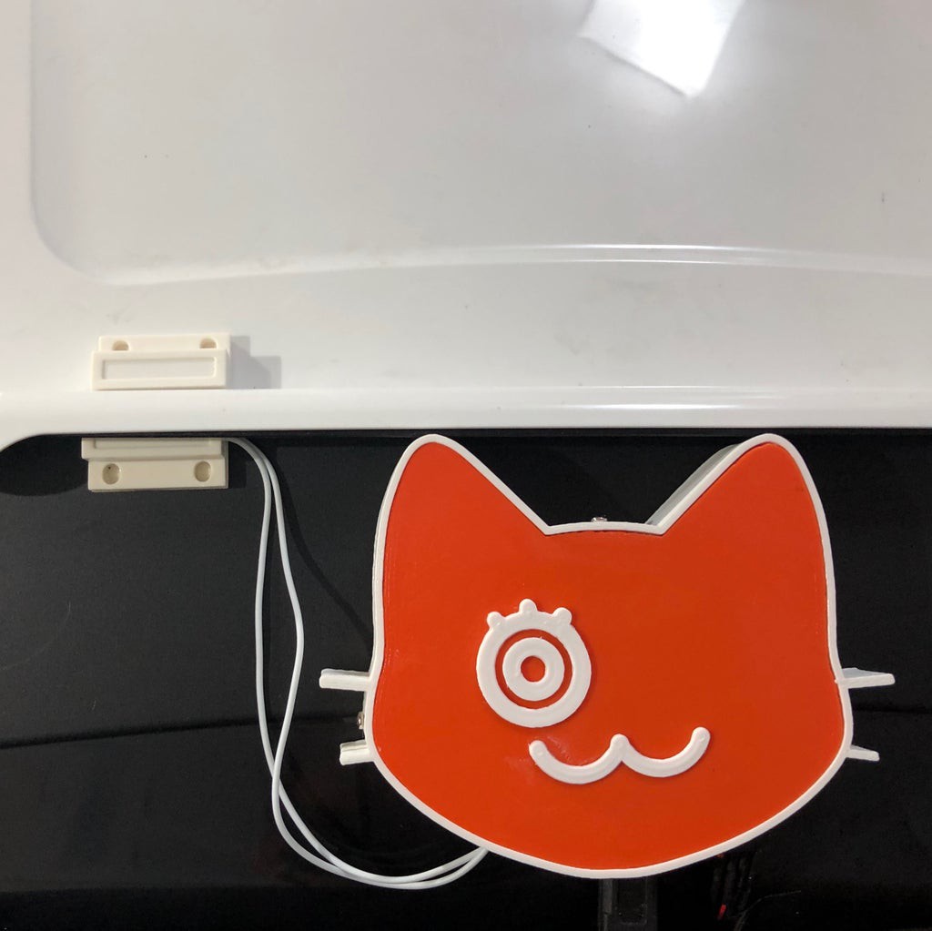
![]()
12 - Stick the reed switch on the box (bottom) and the magnet on the box cover (top). Both should be aligned;
![]()
13 - Plug the micro USB connector to power the circuit.
![]()
IoT Cat Litter Box (with ESP32 and Thingspeak)
A cat litter box with WiFi, using an ESP32, able to measure the weight of my cats, monitoring cleaning conditions and store data online


Discussions
Become a Hackaday.io Member
Create an account to leave a comment. Already have an account? Log In.
Hello.
Nice work! But these sensors too powerful for a cat. :-)
Can I see a code for the ESP32?
Are you sure? yes | no