-
PCB Layout
09/10/2019 at 20:20 • 0 commentsWith the prototype circuit working, it was time for the interesting part: PCB design! I planned to use EAGLE for that, I had used it before and had gotten somewhat familiar with its quirky user interface. I had version 7.5 installed, which was from before the acquisition by Autodesk, and didn’t bother checking if they had managed to ruin it yet in newer versions. Someday I should, but then I also resolved that for some future project I’m going to try KiCad and see if it’s any more or less capable and compatible with my brain.
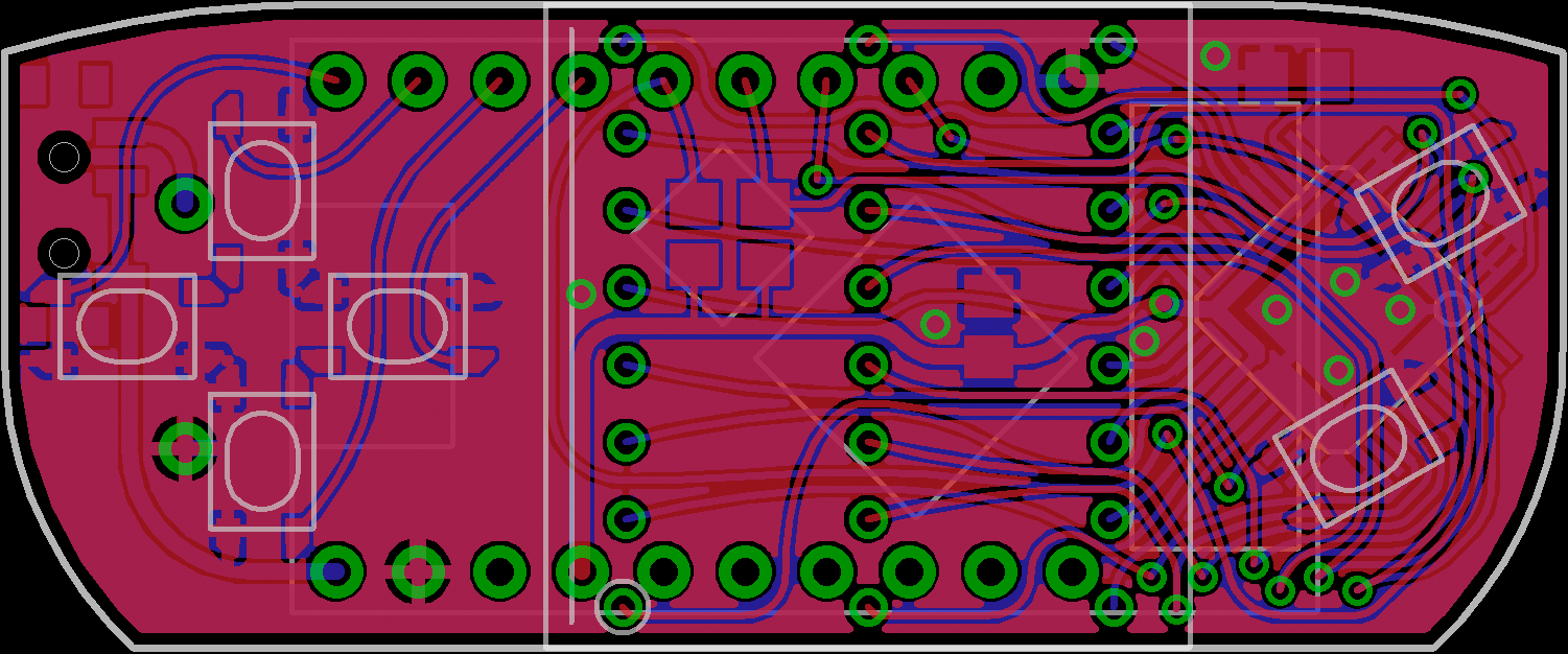
The main challenge in the basic layout was posed by the fact that the spacing between the outer rows of pins of the LED matrix was pretty much the same as that of the TinyPICO, meaning that I couldn’t put them exactly on top of each other. I didn’t want to offset them sideways either however because that would make the board larger, and I was really trying to get it no wider than the LED matrix, 20 mm. A promising idea came in the form of @de∫hipu’s #Matrix Sanitizer, where he had rotated the two layers of pins by 90° relative to each other, which made them interlock perfectly, although with very little space left for pads. These were both on a 2.54 mm grid though, and my matrices had a 7.5 mm by 2.4 mm grid, which didn’t fit between the TinyPICO’s 2.54 mm pins at all. However, since I had found that the matrices could be crammed into a 2.54 mm grid with some force to bend the wires, what about bending just the outer 6 pins into the 2.54 mm grid and leaving all the others on the 2.4 by 7.5 mm one? That worked beautifully on the screen, and it even let me run a trace between the pads on the inside of the TinyPICO pins, which wouldn’t have been possible with all matrix pins on the 2.54 mm grid, but turned out absolutely necessary. How well it works mechanically with the actual matrix remains to be seen when the PCBs arrive.
I proceeded with placing the ISSI chip and wiring it up to the matrix, which turned out harder than expected: The pin row of the matrix closest to the chip caused a bottleneck, acting like a fence through whose gaps a lot of traces needed to go. When using 8 mil traces, I could run two of them between each pair of matrix pins on both sides, except for the outermost ones, where only one would fit because a TinyPICO pin was in the way. That gave me space for 24 traces – just barely enough for 16 matrix pins, 2 I²C lines, 2 buttons, and 2 power lines if I made those 20 mil wide. Whew!
After several iterations of nudging the ISSI chip around to get it farther away from the corner of the board so I could round off more of it, and the corresponding twiddling of traces between the matrix pads, I had a rough layout that satisfied both the design rule check and my desire to squeeze things neatly together for the tiniest board outline possible. It consisted of the usual 45°-angled traces, placed by hand somewhat irregularly because of the different grids involved. That I was not happy with, I want my traces curved, not angular, aligned to the environment, not to an arbitrary grid, neatly curving around obstacles and regularly spaced where several run in parallel.
So, a final round of prettification started. EAGLE’s tools however turned out severely inadequate for that. Maybe not surprising, because this is work that no engineer working on a commercial product would do – but I have the luxury of being a hobbyist, here to spend more time on it because I’m having fun, not less because it costs money. What to do? As always, make your own tools.
EAGLE can be extended with so-called ULPs (user language programs), and learning how to do that was an interesting experience. They are written in a C-like language that is easy to pick up using the documentation, but the system is very awkward because these programs cannot modify the internal data structures of the document, to bend or add traces as I wanted. The document tree is read-only, and the only thing the program can do to modify it is to generate a script that is executed at the end, consisting of commands that basically simulate mouse clicks and command-line entries – it can only do things that a human could do through the UI too.
This required some workarounds and awkward UIs, but in the end I succeeded in making the geometrical tools I needed for my layout prettification: ULPs that make tangents to arcs, intersect lines, tangentially extend or offset curves, interpolate with biarcs, and place wires exactly centered between two pads. I might release them in the future after they mature some more.
![]()
After prettifying the traces, I turned to the silkscreen. Apart from minimal component labels, I wanted logos, revision information, the URL of this project, and some decoration there. For the graphical elements, there are converters that can import SVG into EAGLE, but I seemed to remember that last time I tried that, I wasn’t quite satisfied with it, so I did it my own way: After preparing the polygons in the right way in Inkscape, converting them from SVG path syntax to EAGLE’s XML library format becomes a simple series of text search-and-replace operations.
For the text, since I consider EAGLE’s built-in vector font aesthetically beneath my dignity, I had previously done the same thing for some reusable elements like “ON” and “OFF” labels, but that approach wouldn’t scale to one-off things like the project URL. Instead, I made a library containing all ASCII characters as polygons in a nice font derived from Myriad, created in Inkscape using curve-offset and flattening operations, and many manual tweaks where those didn’t yield satisfying results. (Myriad, despite looking quite even, has a suprising variance in stroke width and is not easy to approximate with a constant stroke!) Together with a ULP that would string these glyphs together in the correct advance widths, I had a rudimentary typesetting tool for acceptably-looking text – even though again with an awkward UI: because a ULP has no access to library elements that aren’t already present in the document, it needs to import all needed glyphs first (heaping them on top of each other), and them measure and typeset them in a second call. (I could have stored the advance widths in the ULP instead of the library to avoid that, but that didn’t feel right either.)
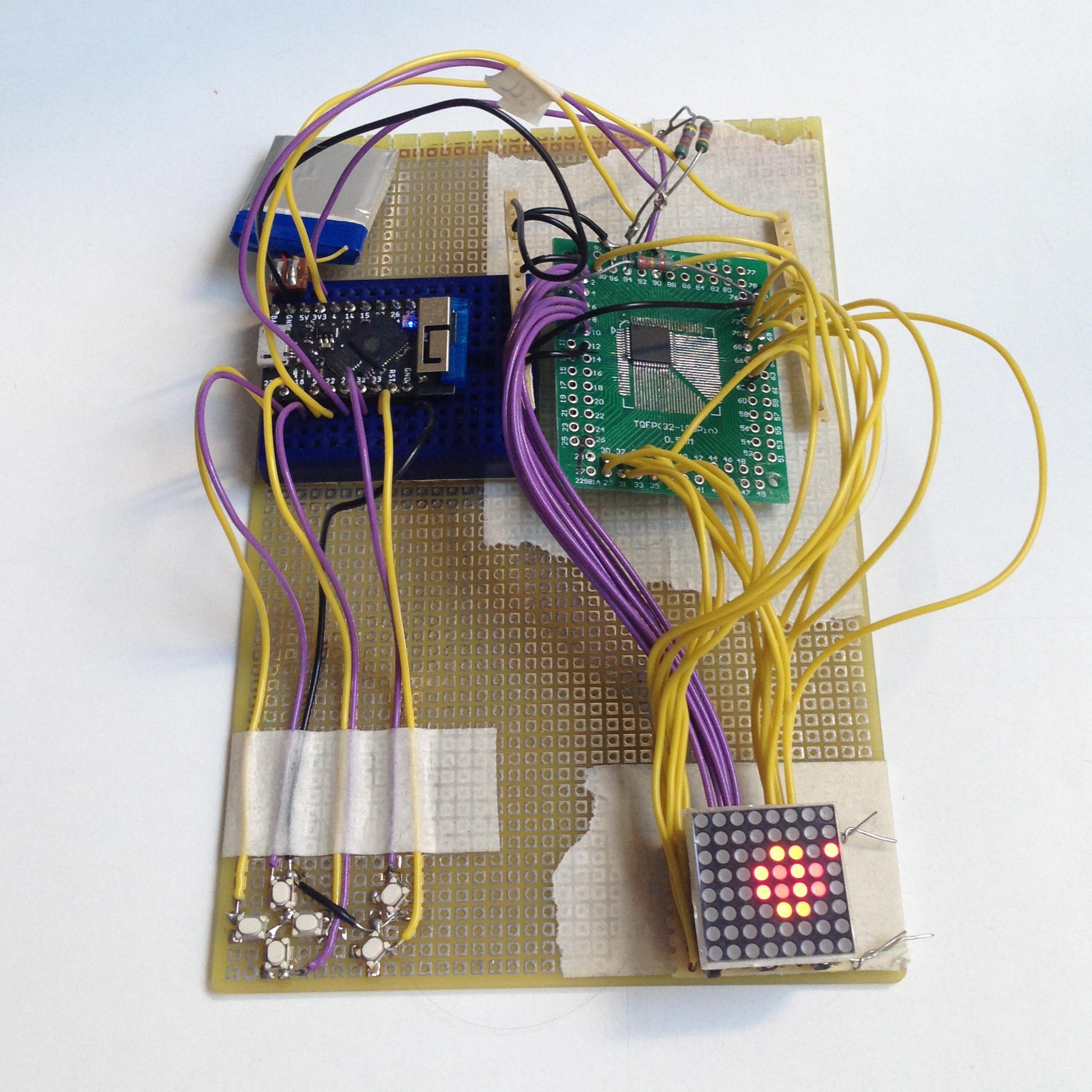
I had chosen different GPIOs for the buttons on the PCB than in the prototype to simplify the layout, and also wired the LED matrix to the ISSI chip a bit differently, partly for the same reason. The other reason was that in the prototype, I had wired all the green column pins of the matrix to the first half of CS outputs and all the red columns to the second half, which made for an awkward layout of color values in the frame buffer. On the PCB, I had now wired the green and red columns alternately instead, which meant that the green byte and the red byte of the same pixel would now be adjacent in the frame buffer. I rewired the prototype to match that layout and adjusted the software.
![]()
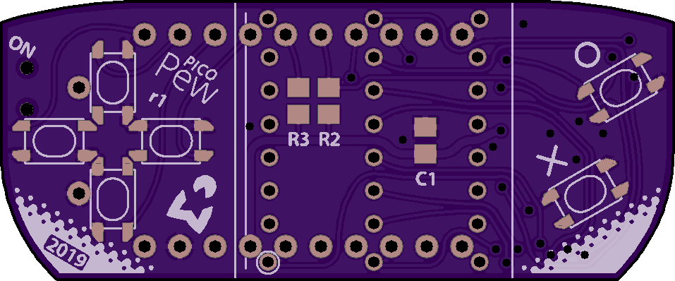
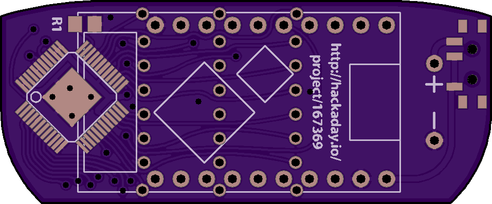
That worked, and after a final double-check that the wiring of the prototype matched the PCB, as well as inspecting the Gerber files in Gerbv and printing them out in original size to check if I had gotten all the component sizes right, I was confident that the board was ready for production. I placed an order for a prototype batch at OSH Park and got these nice pictures.
![]()
![]()
Miraculously, the rewiring of the prototype had also fixed the one dead pixel – I could now turn on all the LEDs. How could that be? I was expecting that there would simply be a different dead pixel now. Apparently it wasn’t a broken memory cell after all, but how could the wiring affect a single LED? I was quite perplexed, until I remembered that at the end of the rewiring, I had removed an accidental solder bridge between two stripboard traces from the matrix base board, which I had assumed had happened during the rewiring. Apparently not, it had been there all along, and by connecting one row pin to one column pin, it shorted out one LED. Doh! I could even have detected that in software using the short detection, but for some reason it hadn’t occurred to me to try that.
This post concludes the retrospective series, we have now caught up with the current state of the project. I am waiting for the PCBs to arrive from OSH Park, which should happen in the next few days, and am eager to try out if my design works!
-
Power Consumption
09/08/2019 at 21:30 • 8 commentsOne of the nice features of the IS31FL3733 LED driver is that it has separate power supply pins for various parts, which allows running the I²C communication at a different voltage than the LEDs. I could therefore leave the communication at 3.3 V as required by the microcontroller, but connect the LED drivers directly to the battery at up to 4.2 V, which means the LED current would not have to go through the voltage regulator of the TinyPICO and part of the power be dissipated as heat there. Would that allow me to save power, a desirable thing when planning to use a battery as small as a 100 mAh LiPo? I took some measurements to find out.
In the final series of measurements, I powered the TinyPICO through its BAT pin from my bench power supply at different voltages – simulating a battery at different charge levels – and measured the total current there, with all LEDs fully on, but with different global brightness values, and with the power pins of the LED driver connected to either the BAT pin or the 3V3 pin on the TinyPICO. As a brightness reference, I used a PewPew Lite and adjusted the global brightness on the prototype until their brightnesses visually matched.
The results were not what I initially expected, but in hindsight completely explainable: It made no difference at all to the total current consumption at the same brightness whether the LED driver was connected at 3.3 V through the voltage regulator or directly to the battery. The current was constant independently of the supply voltage (once the voltage was high enough to actually reach that current, which except at the highest brightness setting generally happened earlier than the ESP32 would even run), varying from 50 mA at the lowest brightness to 350 mA at the highest. The brightness would not vary with the supply voltage, the match with the reference PewPew was always at the same setting. In other words, the additional power available with the higher voltage did not make it into light as I had hoped, but was dissipated somewhere in the driver chip or in the LEDs themselves.
Thinking about it afterwards, I realized that this was exactly the way it needed to be. The average current through an LED needs to be held constant not just over various numbers of LEDs being on, but also over various supply voltages, because on a power supply with a nonnegligible internal resistance, the voltage will automatically vary with the number of LEDs being on, and we do not want the brightness to vary then. Also, since the brightness of an LED is approximately proportional to the current, its power efficiency decreases with increasing voltage, and it is not beneficial to run it at a higher voltage but lower PWM duty cycle.
Another effect of connecting the LED power to the BAT pin is that when the system is running without a battery, powered from USB or the 5V pin, the LEDs are powered through the battery charger. It turned out that the charger was very confused by that load that didn’t act like a battery and would sometimes deliver little current and sometimes a lot, resulting in a randomly shifting display brightness.
In conclusion, since there was no power consumption advantage to connecting the LED power directly to the battery, but a disadvantage in the case of running without a battery, I decided to connect it to 3.3 V along with the logic power. This would also make the circuit simpler, and the voltage regulator of the TinyPICO, rated at 700 mA, should take it easily.
-
Adding Buttons
09/07/2019 at 16:18 • 0 comments![]()
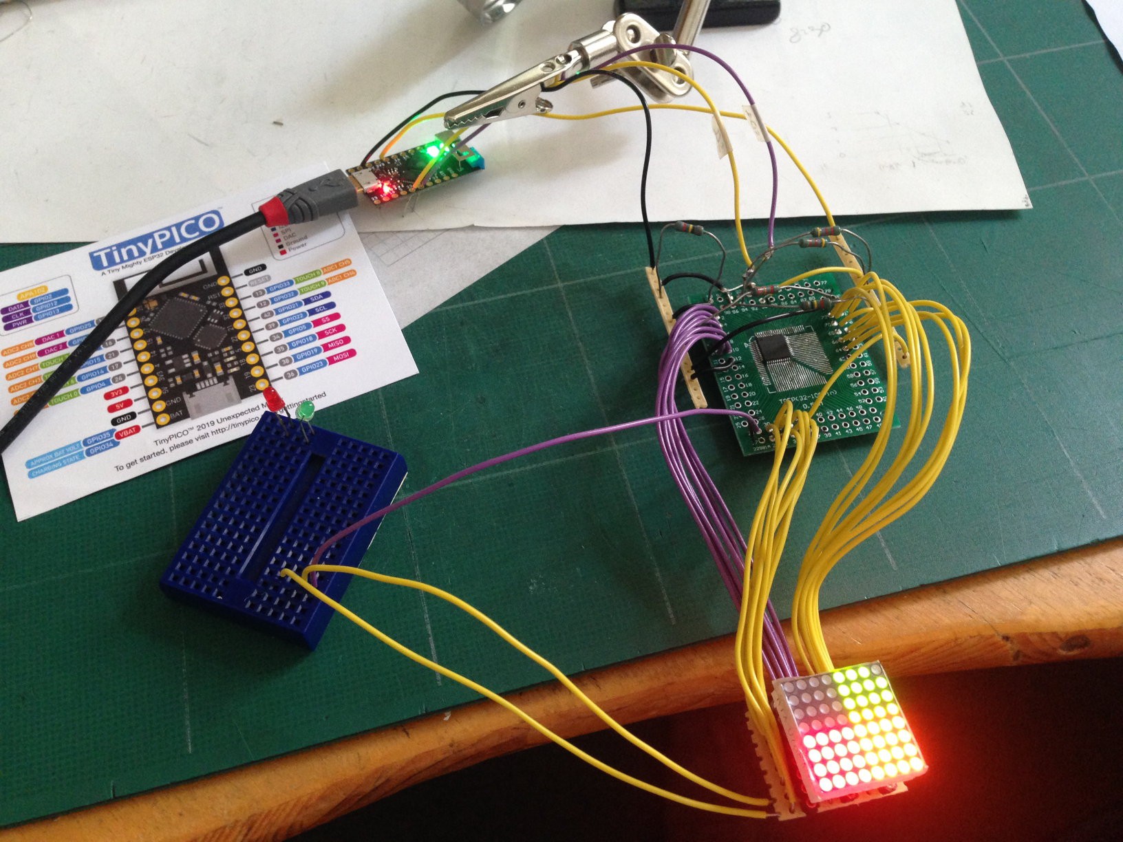
Meanwhile, my TinyPICOs had arrived, and the picture shows one driving the prototype. With the wires going to the breadboard on the left, connected to one unused row output on the green PCB and two column outputs at the matrix, I was testing whether I could use the open/short detection feature of the ISSI chip to read buttons. It worked in principle, I could detect from the software whether the wires were connected, but unfortunately a scan resulted in a visible flash of the display, either dark when set to the minimum current as recommended, or bright at a higher current. I therefore concluded that this was not a practical solution.
As alternative solutions for connecting the buttons, I considered using some IO expander chip or a second microcontroller such as an ATtiny. With the latter, I would also be able to offload the latching feature of the PewPew key reading API from the main microcontroller (it remembers which keys have ever been down since the last check, no matter how briefly). Either would be connected to the same pair of I²C pins as the display driver and thereby leave lots of other GPIOs available for other uses, such as maybe a 12-pin PewPew Standalone connector. The disadvantage, on the other hand, would be the space needed on the board for at least one additional component, which might compromise my goal of making the device as tiny as possible.
In the end, I decided to just use ESP32 GPIOs for the buttons – the TinyPICO had enough of them, and I was unlikely to need them for anything else. If I left DAC1 and GPIO4 open, it would still be possible to connect an official TinyPICO audio shield, for people who want their games to make noise. (I usually don’t and am happy with the lack of sound in the PewPew standard.)
I had bought some tiny buttons from Mouser, with a rectangular package, a relatively large cap that is still comfortable to push with bare fingers, and a nice clicky feel. The same size was used in the PewPew Lite for D1 Mini. I experimented with several arrangements and settled on one where the directional buttons are arranged in a cross, visually emphasizing their meaning. It uses a little more space than the most compact arrangement possible, but assuming that I would arrange the buttons to the left and right of the display, as in the FeatherWing, my preferred arrangement, I would have that space. Whether to choose that arrangement or the Gameboy-like arrangement below the display as in the D1 Mini shield would be decided later based on what was easier to achieve in the PCB layout.
Radomir later also graciously gave me two of the impressively small D1 Mini shield PCBs. After populating them (including working around some design flaws where he had pushed Fritzing to its limits), I could test that arrangement and found that the buttons were a bit too close to the display, and the two groups a bit too close to each other, for me to comfortably use with two thumbs.
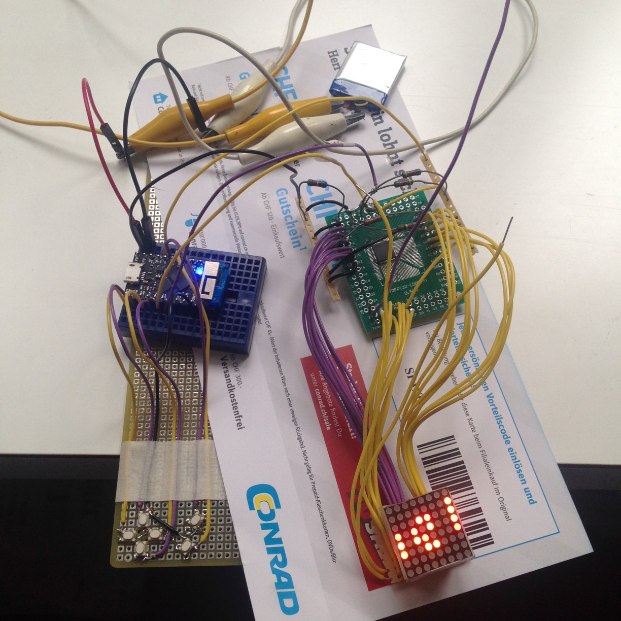
For my prototype, I soldered six buttons in my chosen arrangement onto a corner of an upside-down perfboard (luckily they fit well onto its 2.54 mm grid) and attached wires that would go into the breadboard with the TinyPICO.
![]()
With this, all the hardware for a fully functional PewPew was in place, and of course I couldn’t wait to also get the software ready. I started from the MicroPython pew library for PewPew Lite and replaced the display and key functions by ones suitable for my hardware. I used pin interrupts to read the buttons and at first only looked at which pin triggered the interrupt to recognize which key was pressed. This however resulted in some occasional crosstalk between keys: sometimes, pressing one key would register as a simultaneous press of that key and one of its neighbors. I do not know whether these spurious interrupts were caused by inductive coupling between the parallel wires or by something inside the microcontroller. The problem disappeared when I, inside the interrupt handler, actively read the state of all 6 pins to decide which ones were pressed. Success! I was now able to play all the existing PewPew games on my prototype.
-
From Idea to First Prototype
09/04/2019 at 20:10 • 0 commentsImpressed by the engineering that went into them, the first-class MicroPython support, and the sheer tininess, I had ordered some TinyPICO ESP32 development boards from Unexpected Maker’s CrowdSupply campaign. But what to actually do with them, other than sinking them into the drawer of cool but eternally unused microcontroller boards? In the weeks before EuroPython 2019, with my head full of PewPew as I was going to help @de∫hipu run PewPew workshops there, the answer was obvious: Make a PewPew shield for them! I had never designed a PCB more complex than a bristlebot kit, so this might be a nice exercise, not totally uncharted terrain but not without challenges either.
The easiest way of doing this would be to copy the circuit of the PewPew Lite FeatherWing. The problem with that is that the Holtek HT16K33 LED matrix driver used there only exists in a relatively large SOP-28 package. It fits between the pins of the Feather, but not between those of the TinyPICO (and not those of the LED matrix either), making it impossible to build an appropriately tiny device with it.
Looking for alternatives, I turned to @de∫hipu’s excellent article and was intrigued by the ISSI IS31FL3733 that he had also used in his PewPew Pro. It comes in an eTQFP-48 package that is reasonably small but hopefully still within my soldering skills. Beyond the capabilities required for a PewPew, it would offer 256 shades of brightness for each individual LED, multiplied by 256 levels of global brightness. It however lacks the key scanning feature of the Holtek chip, but I wondered whether its capability of detecting shorted LEDs could be misused for that. So I ordered some of these chips from Mouser.
For the LED matrix, I was thinking of using the same 20 mm red/green one as in the PewPew Lite, which I much prefer to the monochrome displays of PewPew Standalone devices, because the colors are easier to distinguish. 4 shades of the same color have advantages too, such as allowing antialiasing, but with the ISSI driver I would get the best of both worlds. I briefly went looking for even smaller bi-color matrices, or RGB ones of the same size, but could not find any. When the KYX-788AHG ordered from AliExpress arrived, the first thing I noticed was that, just like on the ones I had gotten from Radomir on PewPews, their pin spacing was not actually 2.5 mm as specified, but around 2.4 mm instead, making them hard to squeeze into 2.5 mm (or even 2.54 mm) holes. The larger spacing of 7.5 mm was accurate though.
To test my understanding of how to use the ISSI LED driver, I mounted one of them on an adapter board and wired it up to a matrix and to an ESP8266 Feather HUZZAH board running MicroPython. Figuring out how to control the LEDs that way was not hard with the help of the data sheet and the MicroPython REPL, but I ran into two problems:
- One of the LEDs would always stay off, the green one in the upper right corner. The LED itself was fine, it could not be the wiring because that would affect whole rows or columns, and an off-by-one error in my code could be ruled out because the way I assigned rows and columns, the respective bits were located in the middle of the buffers, not at the edge. I finally concluded that I had probably fried some memory cell with my clumsy soldering, but I was unable to figure out whether it was in the LED On/Off bitmap or in the PWM buffer, because the registers are write-only.
- Whenever I turned on too many LEDs at once at a certain brightness, the chip would just reset, turning the display black and requiring me to redo the whole initialization sequence. The numbers were somewhat random and varied with whether I supplied power from the 3.3 V or 5 V output of the microcontroller board or from a bench power supply, and there was also no clear pattern to how much current I could draw before the reset – but in all cases I was never able to turn on all LEDs at full brightness. It turned out that the cause was my neglecting to add the decoupling capacitors shown in the reference circuit at every power pin – once I added one 1 µF ceramic SMD capacitor (the closest thing I had lying around) across the supply, the symptom disappeared and I could run all LEDs at full brightness at once. With the 22 kΩ current control resistor I chose, the full brightness was quite bright and consumed a total of about 350 mA.
This is the first in a series of catch-up posts on the past history of the project, more to come!
 Christian Walther