This device will have a limited sampling rate, and hence will need to filter the input signal to prevent aliasing. I've borrowed some data from here for a 9W smart LED bulb: https://github.com/plinioseniore/reactive_power
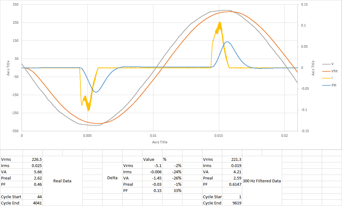
This is somewhat of a "worst case" since it's neither resistive nor reactive load, but a switching power supply which pulls current at nearly the peak in the voltage waveform, producing a current draw with lots of high frequency components.
I've assumed that I will sample at 600 samples per second, though I could theoretically go much higher. This means I need a 300 Hz cutoff frequency on my anti-aliasing filter. I've used TI's WEBENCH tool to get values for a "Lowpass, Multiple Feedback, Linear Phase 0.5deg" filter, which I then simulated with modeled op-amps in LTspiceIV, and imported the data back into Excel to plot and run calculations on. Results are below:
Discussions
Become a Hackaday.io Member
Create an account to leave a comment. Already have an account? Log In.