Close
0%
0%

Wi-Fi Power Switch

ESP8266 based smart power switch/dimmer with Kill-A-Watt class power/power factor readings

Similar projects worth following
ESP8266 based smart power switch/dimmer with Kill-A-Watt class power/power factor readings

This started with my desire to modify my Kill-A-Watt meter to report power to Thingspeak. Got it mostly working, but still had some offset/inaccuracy issues due to sampling rate (and discovered it was off by a factor of 2 because the original X2 power supply capacitor failed on the Kill-A-Watt). Ended up magic-smoking it while I was programming it so I am now scrapping that to work on a new, from-scratch power meter/IoT switch. First picture in the gallery is the original Kill-A-Watt prototype, second is a vaporized power trace to the KaW op-amp, and third is a magic smoked ADC. Reverse engineered schematic of the Kill-A-Watt circuit can be found here: http://www.mikesmicromania.com/2013/03/kill-watt-circuit-analysis.html

This will have a couple versions:

1. Basic power meter only, records V/I/PF and reports to Thingspeak or similar

2. #1 plus 16A relay for on/off load control

3. #1 plus 10A triac for dimmer control of lamp or motor speed control

4. #2 or 3 with OLED display added for real time view of power usage, kWH or voltage/current waveforms

Instead of being a "brick" that plugs into an outlet, I will be designing this as more of a short extension cord. Doubles as an outlet saver for power bricks that take up lots of space :)

Basic specs:

Voltage: 85-250VAC

Current: 0-16A (relay version), 0-10A (dimmer version)

Power Factor: 0-1

Resolution: 0.2V, 0.01A (high range, 1.6-16A), 0.001A (low range, 0-1.6A)
  • Filtering and Sampling

    Justin Kenny11/01/2016 at 01:25 0 comments

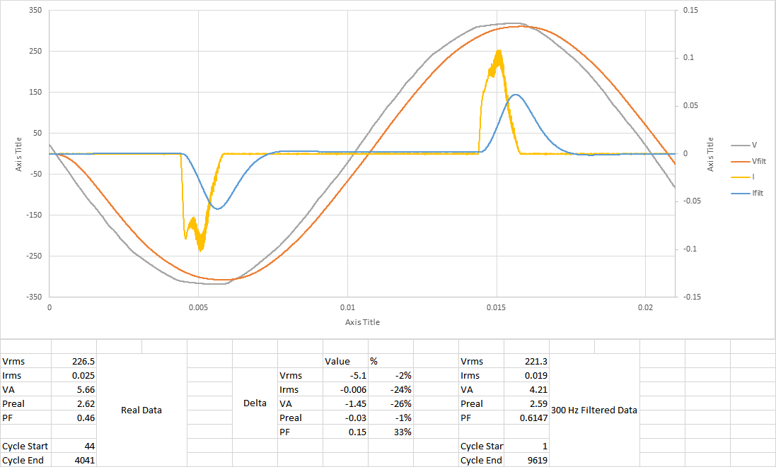
    This device will have a limited sampling rate, and hence will need to filter the input signal to prevent aliasing. I've borrowed some data from here for a 9W smart LED bulb: https://github.com/plinioseniore/reactive_power

    This is somewhat of a "worst case" since it's neither resistive nor reactive load, but a switching power supply which pulls current at nearly the peak in the voltage waveform, producing a current draw with lots of high frequency components.

    I've assumed that I will sample at 600 samples per second, though I could theoretically go much higher. This means I need a 300 Hz cutoff frequency on my anti-aliasing filter. I've used TI's WEBENCH tool to get values for a "Lowpass, Multiple Feedback, Linear Phase 0.5deg" filter, which I then simulated with modeled op-amps in LTspiceIV, and imported the data back into Excel to plot and run calculations on. Results are below:

    As you can see, the filtered result drops quite a bit of peak current compared to the real data, but the real power calculated remains almost the same as the original, only 1% low. The power factor got the worst hit, with a 33% difference, and hence the apparent power is quite a bit lower than expected as well. These values will get worse with sampling applied on top of the data, which I will simulate tomorrow. Based on these results I may choose to increase the sampling frequency to 1.2 ksps or higher, it will take some fiddling with actual hardware to see how fast the actual ADC can sample with Arduino on ESP8266.

  • Current + Voltage Sensing

    Justin Kenny10/31/2016 at 19:41 0 comments

    For current sensing I will be using a set of op amps to amplify the voltage across a 2mOhm shunt resistor on the low side (neutral). The resistor selected is the following: http://www.digikey.com/product-detail/en/bourns-inc/CRE2512-FZ-R002E-3/CRE2512-FZ-R002E-3CT-ND/4900088

    The power dissipated in the resistor is 16 Arms^2*0.002 ohms = 0.512 W. The peak voltage drop is +/- 45.3 mV. The voltage will be AC coupled and DC shifted by 2.048 V, then multiplied by 40 or 400x to make the most of the ADC's range and capture both sides of the waveform. The signal will also be filtered to remove components over the ADC's sampling frequency of 600sps.

    Voltage sensing is much simpler, it will be done through a voltage divider which cuts the voltage down by a factor of 201x. The voltage will also be fed through an identical filtering/op-amp network such that the phase response will be the same as the current amplifiers so the real power calculation is still correct for high frequency components that may be phase shifted.

  • Basic Math for Triac

    Justin Kenny10/28/2016 at 19:46 0 comments

    Just a quick note, did some reading on Triacs last night from this ST micro app note: http://www.mouser.com/catalog/specsheets/stevalill004v1.pdf

    Determined that with a BTA16-600CW3G Triac, I can run it at up to around 10A with 38mm heatsink (4.4C/W at 35C ambient). I bought some 34mm TO-220 heatsinks from eBay, I'll do some experiments to see if it can handle the ~10W load that the Triac will dissipate at 10A. May need to drop from 1200W power control down to 1000W if not.

    Looks like the relay will be this part: http://www.digikey.com/product-search/en?keywords=PB1267-ND

    $2.02 for single unit price, can handle 250V/16A (4000VA switching), and has a similar sized footprint as the Songle 10A cheapo relay that I was initially planning.

View all 3 project logs

Enjoy this project?

Share

Discussions

Similar Projects

Does this project spark your interest?

Become a member to follow this project and never miss any updates