Close
0%
0%

Low-cost EEG circuit

Design and implementation of a low-cost, single-channel, EEG prototype circuit

Similar projects worth following
Commercial electroencephalography devices can cost thousands of euros depending on the complexity of the instrumentation. The objective of this project is to try to develop a very simple and cheap EEG device able to measure brain activity while preserving a sufficient level of accuracy.

The resulting system is a single-channel EEG device consisting of:

- 3 passive electrodes: 2 to measure the voltage difference across the skull and the other one connected to the body as a ground reference.
- The main EEG acquisition circuit: the core of the device, able to amplify the voltage difference detected by the electrodes and to reject noise and interferences.
- An Arduino Nano board: used to capture and read the signals processed by the previous circuit.

To develop the circuit I referred to several projects much more accurate and complex than this, such as the openEEG project and various publications concerning the implementation of EEG devices (the most important was the one published by Lei Zhang and colleagues).

Finally I would like to point out that I am almost a newbie in the field of applied electronics, for this reason some errors (I hope not too catastrophic) may be present, so I would be happy if more experienced people than me could possibly correct my mistakes.

EEG.asc

LTspice model of the circuit

asc - 12.83 kB - 08/29/2019 at 22:31

Download

  • 1
    RFI filter & protection circuit

    The first stage of the circuit is designed to provide a Radio Frequency attenuation and an overloads protection.

    For the first purpose a differential low-pass filter capable of remove as much RF energy from the input lines as possible is used. The filter consists of the resistors R1a R1b, and the capacitors C1, C1a, C1b which form a balanced bridge circuit.

    The protection circuit is obtained connecting 4 diodes as shown in the LTspice schematic in order to guarantee an adequate protection against damage to the amplifier and the user.

    The output of the two electrodes related to the positive and negetive channels must be connected in series with resistors R1a and R1b.

  • 2
    Instrumentation amplifier

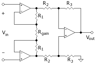
    The instumentation amplifier is the most important part of the circuit, it takes 2 voltages as inputs and outputs the difference between the two multiplied by the gain factor. The main features of this component are: very high common mode rejection ratio, very high input impedances, low noise and very low DC offset. Its structure derives from the differential amplifier, with respect to this it has two more op-amp (input buffers) that increase the input impedance and allow the amplification of the differential input signal (Vin) to be varied by varying only one resistor (Rgain).

    In general it is possible to build an instrumentation amplifier by connecting 3 op-amps and 7 resistors as shown in the previous figure, however unless you make it with precision resistors, it will suffer from a low common mode rejection ratio.

    For this project I decide to use the INA128 with an appropriate gain resistor Rg in order to obtain an amplification factor G between 10 and 15. It is not convenient to amplify too much because of DC component. However, when I built the circuit I was not yet in possession of the INA128, so I had to adapt by building the in-amp using 3 op-amps as I explained before, I will update the project as soon as I receive the component.

  • 3
    Driven right leg circuit

    The purpose of the driven right leg circuit is to feedback any noise from the signal to the body in order to minimize any common mode interference on the body and strengthen the signal.

    The third electrode, the one related to the reference ground connection, must be connected to the output of the driven right leg circuit.

View all 9 instructions

Enjoy this project?

Share

Discussions

Milan Mirčić wrote 07/06/2021 at 15:41 point

Hello! Love the project. Question: what program did you use to get the data as a waveform?

  Are you sure? yes | no

Similar Projects

Does this project spark your interest?

Become a member to follow this project and never miss any updates