 victor-chew
-
1Step 1
My full project diary can be found here. There are very few parts required, and all of them should be quite easy to obtain. Connect the ESP-12E dev module to your laptop via a standard micro-USB cable. Then install the Arduino IDE and follow the steps here to configure it for ESP-12 support. You also need to install WiFi Manager using the IDE's Library Manager. Once you have the environment set up, try running the sample WiFi Manager sketch and connect to the configuration access point. My own experience was quite smooth-sailing. I got everything up and running in 30 minutes or so, half of which was waiting for things to download.
![]()
-
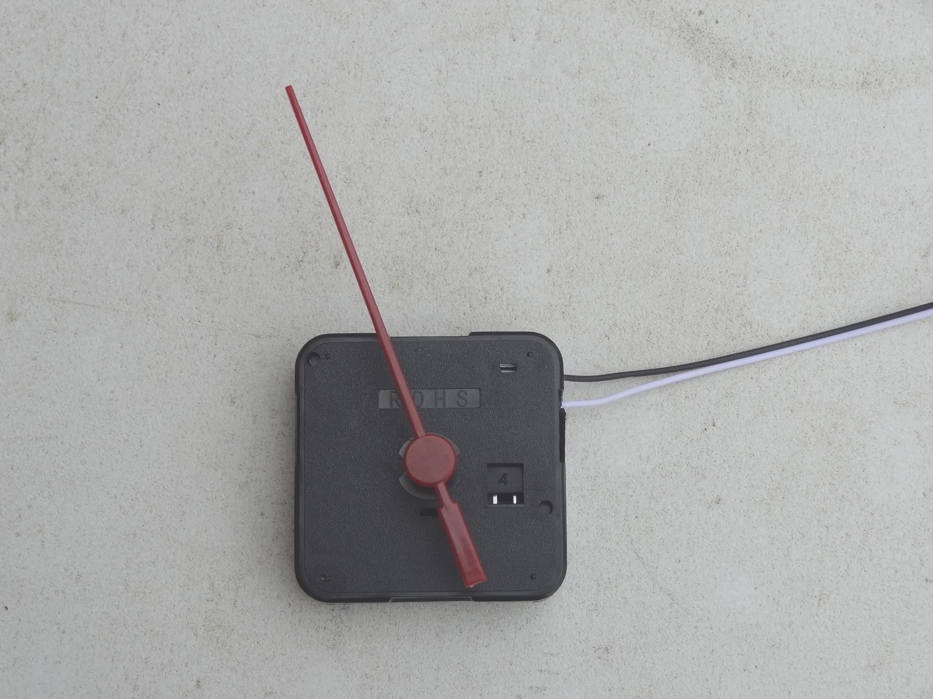
2Step 2
Once the development environment is set up and running, we need to take apart the Ikea clock and solder 2 jumper wires to the clock mechanism. Remember to verify that the clock mechanism has been re-assembled correctly by driving it using an AA battery. The first time I did that, the second hand wouldn't tick properly due to suspected gear misalignment. The second time was a success.
![]()
-
3Step 3
Connect the jumper wires to pin D1 and D2 of the ESP-12 and run the sample clock driver sketch (make sure there's no battery in the clock!). The clock should tick as per normal.
-
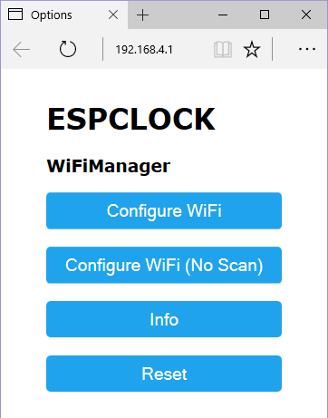
4Step 4
Once the clock is verified to be properly driven by the ESP-12, you can upload the final sketch to the ESP-12 and configure the clock by accessing the configuration AP. Reply "Share" if the browser asks if you would like to share your location with the config portal.
-
5Step 5
That's it! All done!
ESPCLOCK
NTP-enbling a cheap $2 Ikea analog clock using ESP-12/NodeMCU/Arduino
Discussions
Become a Hackaday.io Member
Create an account to leave a comment. Already have an account? Log In.
How do you initialize the clock? I mean, how does your clock software learn the current position of the hands, when it is first turned on? Also, how does the clock deal with occasional failures to advance, when the solenoid receives a pulse or receives an artifact double-pulse?
Are you sure? yes | no