In the
following steps I will tell you how to build my DIY Inkjet Printer,
but first I want to tell you a bit about this project.
Back in 2019
after reading through the build logs of the Oasis 3DP I was searching
on the internet if someone has ever tried to build an inkjet printer
from scratch, at home, with simple electronics and without access to
industrial production lines. I found something about that at the
Reprap Forum and on thingiverse and tried to build their projects.
After successfully building the projects I started the work on this
project.
The design goal
of the project is to build a piezo inkjet printer from scratch. The
first working build had a PMMA printhead and could if everything was
aligned perfectly print with black ink (water + paint color). After
that I started printing the printhead with a SLA 3D printer to be
able to create internal channels for flushing the air out of the
printhead through the nozzle. After some testing with it and building
single and multi printhead builds I wanted to try printing in four
colors or CMYK. I designed the needed parts for that, but I never
tried them out until I recently attempted to write building
instructions for that. For writing the instructions I redesigned the
project to fit it on an Ender 3 and while doing that I figured out
that the machine was far to unreliable to get it working at all. So I
had to find a way to make it more reliable. For that I designed SLA
3D printed piezo pumps instead of the piezo printheads, used MOSFETs
and higher voltage for switching the piezos instead of the H bridges
and used a vacuum duct to carry away the excess ink that would
otherwise block the nozzle with a large ink drop. With these changes
the printer should be ready to do hour long prints whitout failing
due to design based problems.
Printing
CMYK images (with the right software – could not find one for that
)
Printing
along paths ( with any CAM software )
Printing
with four different colors or materials
Maybe you
can use it for binder jetting or even bio printing with low
viscosity materials.
You can
also modify it to match your desired application.
If you like the
project and want to build it, read the following steps in which I
tell you how to build it. Thank you for the interest in my project :)
2
Machine Parts Description
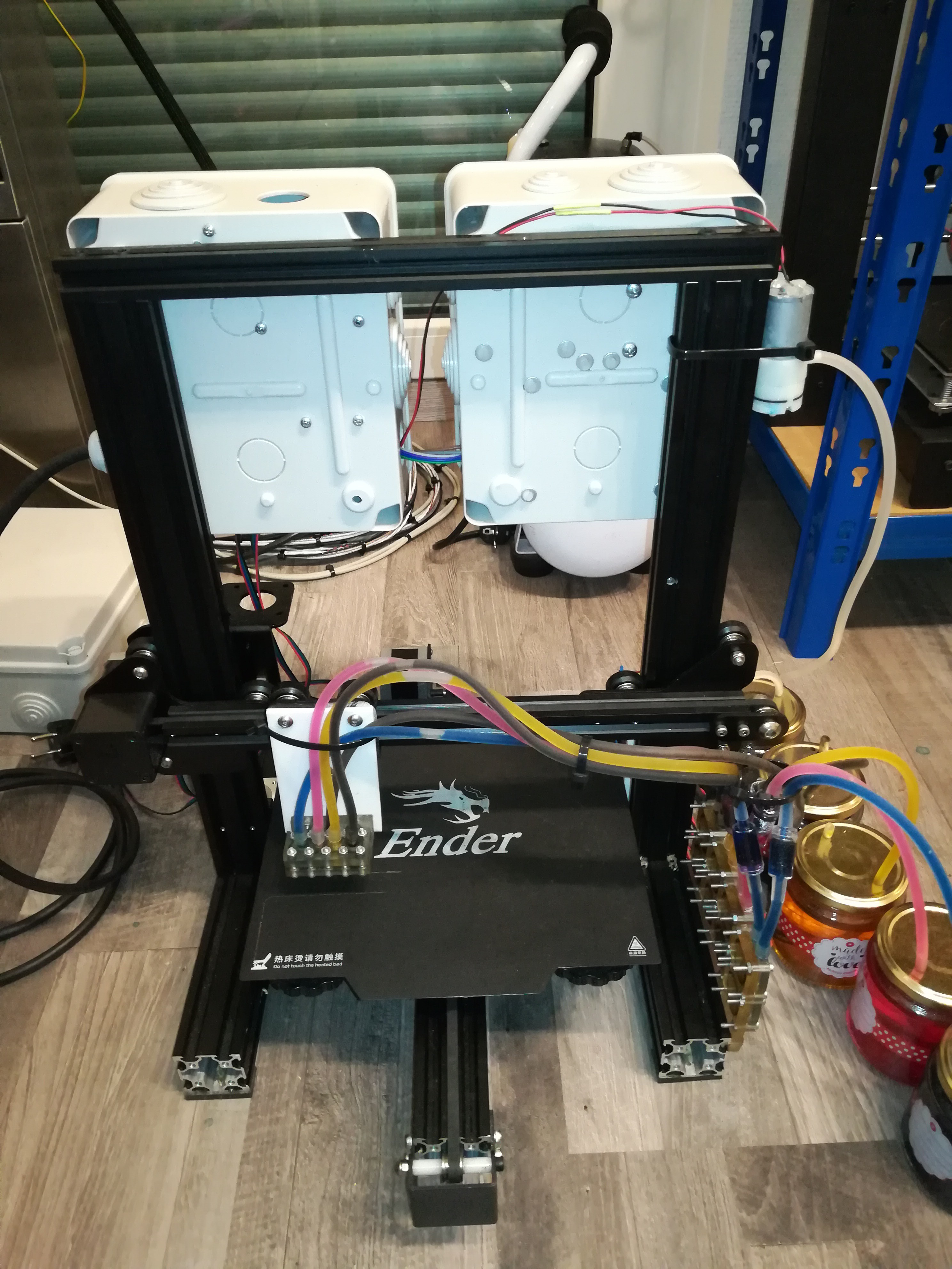
The machine consists of the following parts:
Machine frame with mechanics and stepper motors
Printer controller with stepper drivers, 12V power supply and vacuum pump + Step Down Converter
Piezo driver with Arduino Nano, transformer, 12V power supply, rectifier, MOSFET switch, fuses and WAGO terminals
Piezo pumps with silicone tubing, check valves, ink and excess ink container, ink filters and printhead
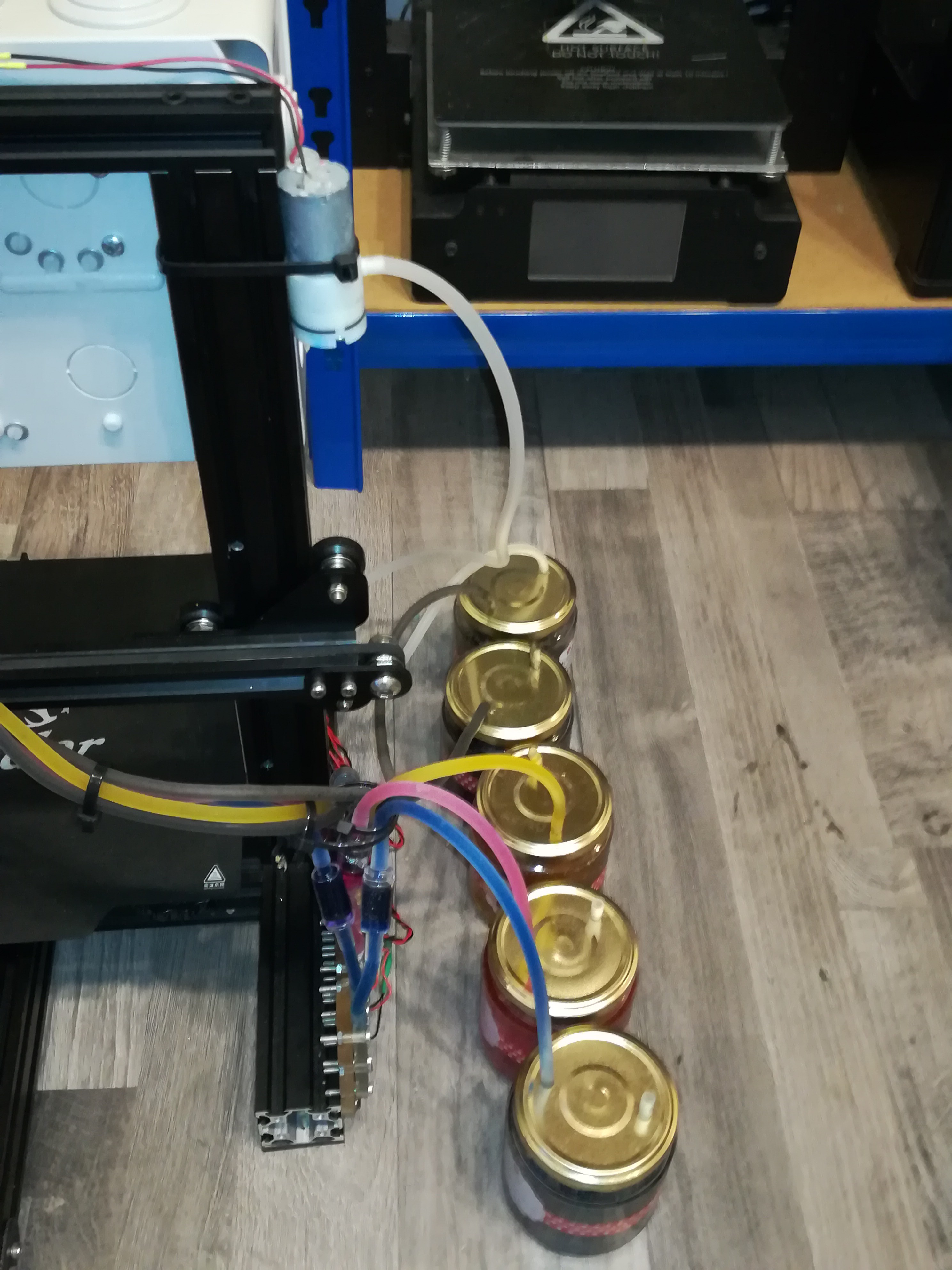
3
Machine Frame
You can start by choosing the machine frame that you want to use for your DIY Inkjet Printer. I used an Ender 3 from which I removed all electronics besides the stepper motors, but you can also use any other machine frame. The machine needs no Z axis and endstops are also optional.
4
3D Printing the Parts
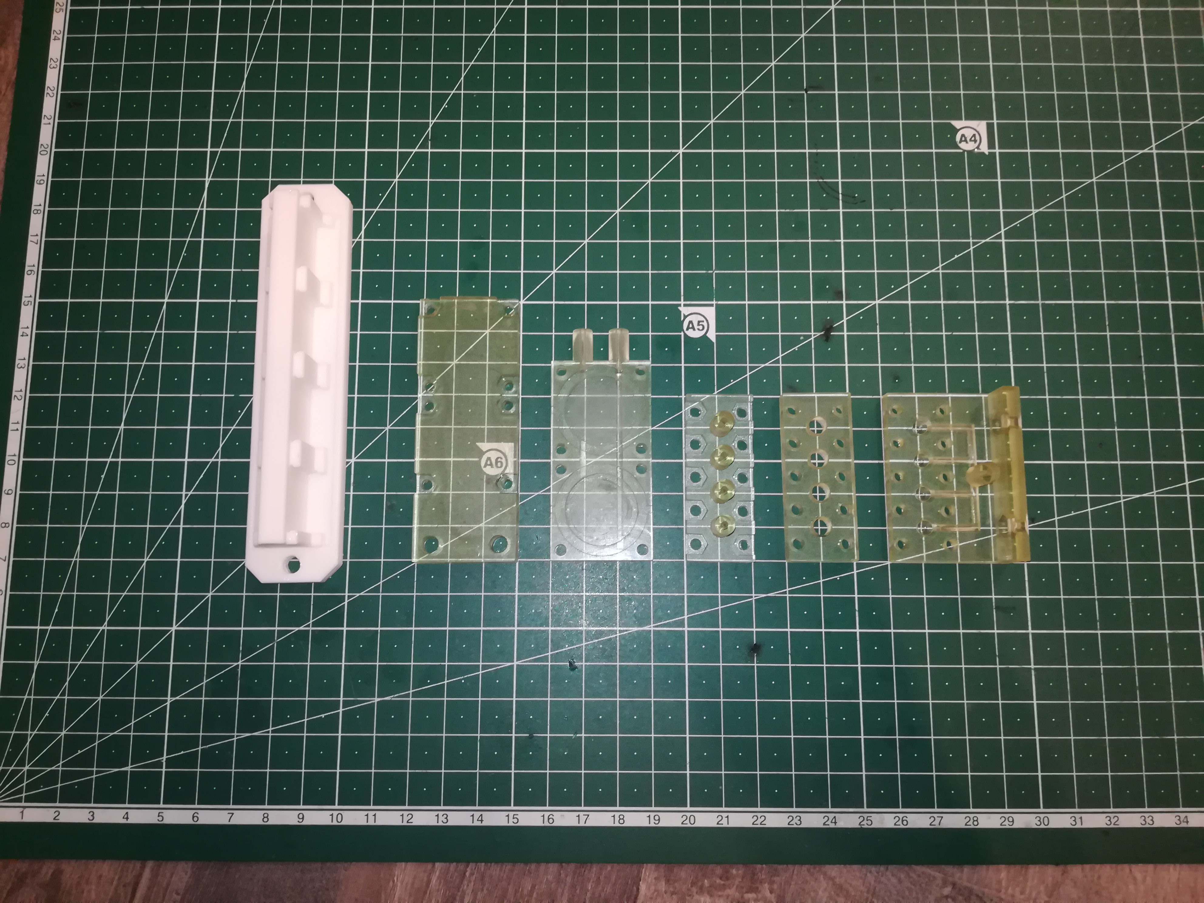
For the machine there are only a few parts that you have to 3D print. I printed the liquid carrying parts in tansparent SLA resin to get them water tight and to be able to see what's going on inside (like air bubbles, flow or leaking).
Needed parts are:
The piezo pump body
The piezo pump cover/mounting bracket
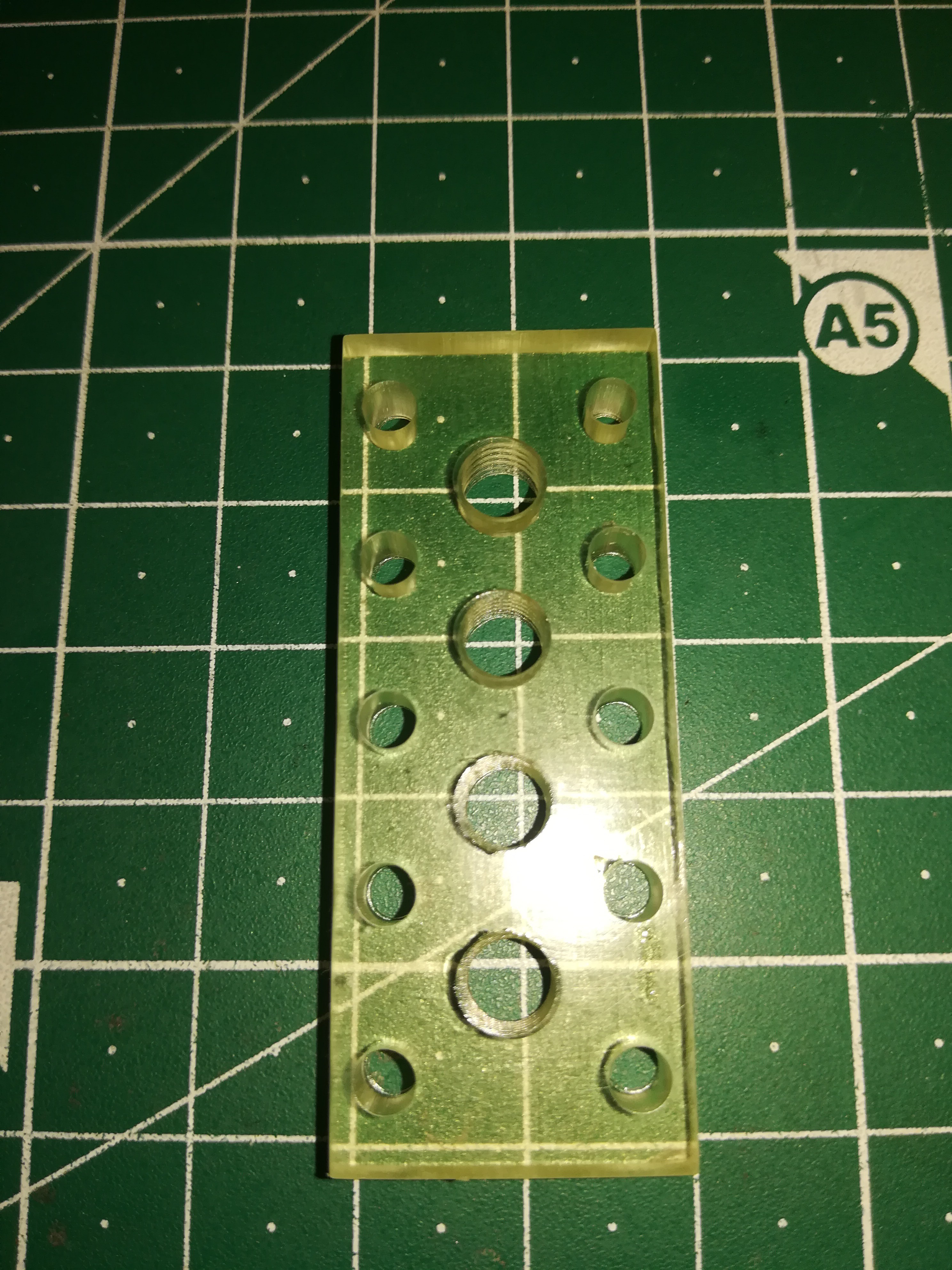
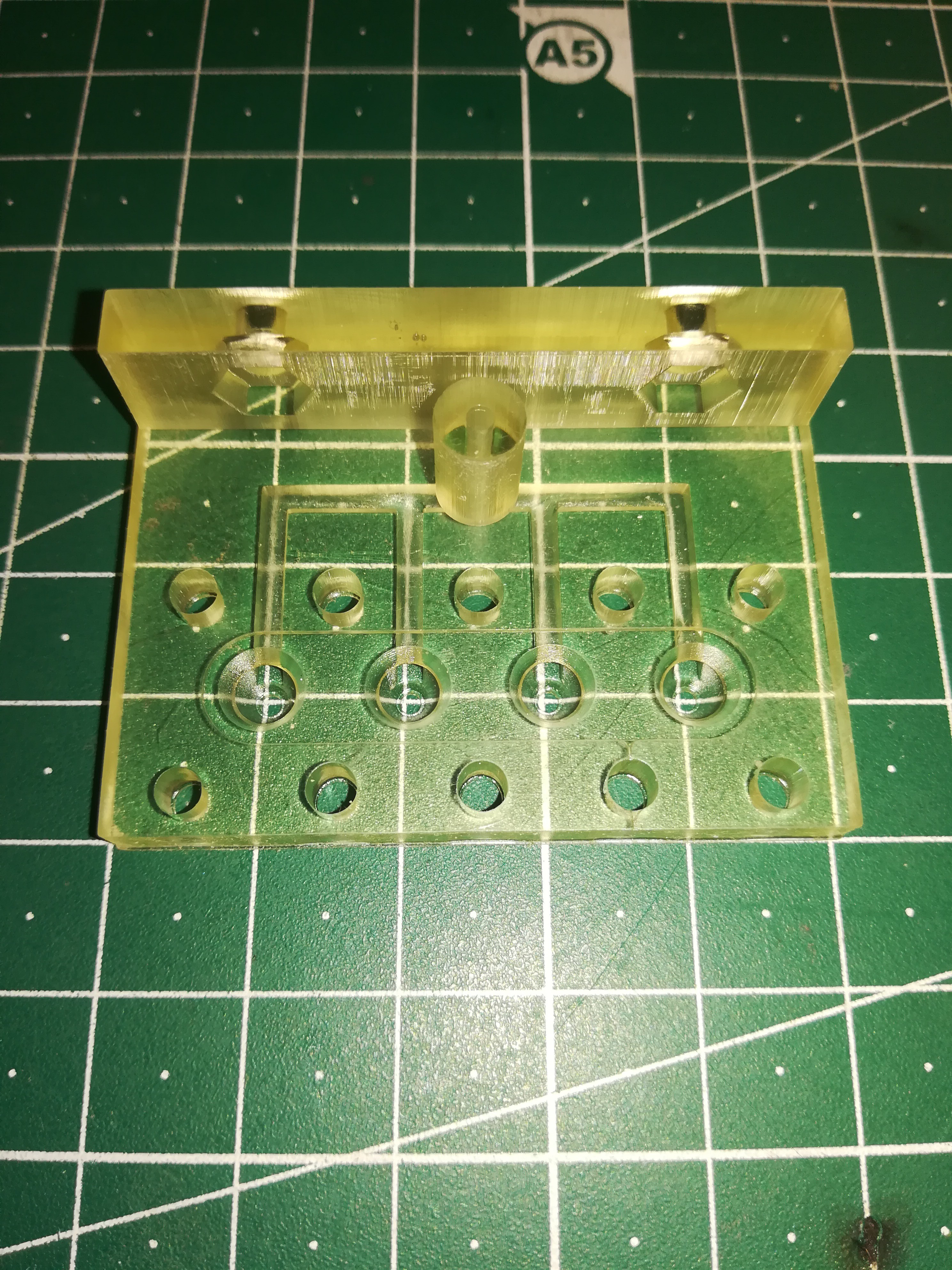
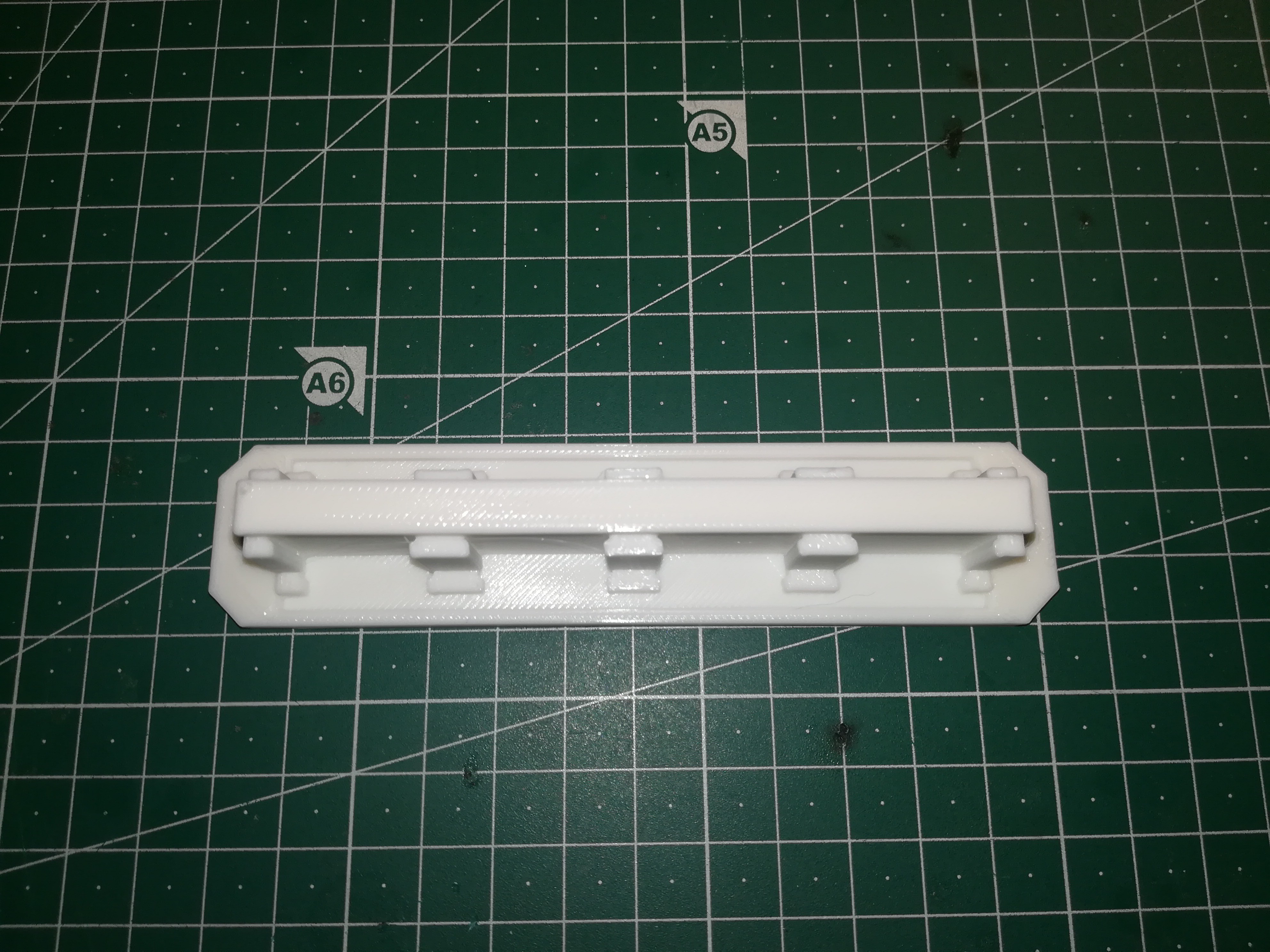
The printhead top (with tube connections)
The printhead middle (with threads)
The printhead bottom (with vacuum duct)
WAGO mounting bracket
A mounting bracket to mount the printhead on your machine, which you have to design by yourself
5
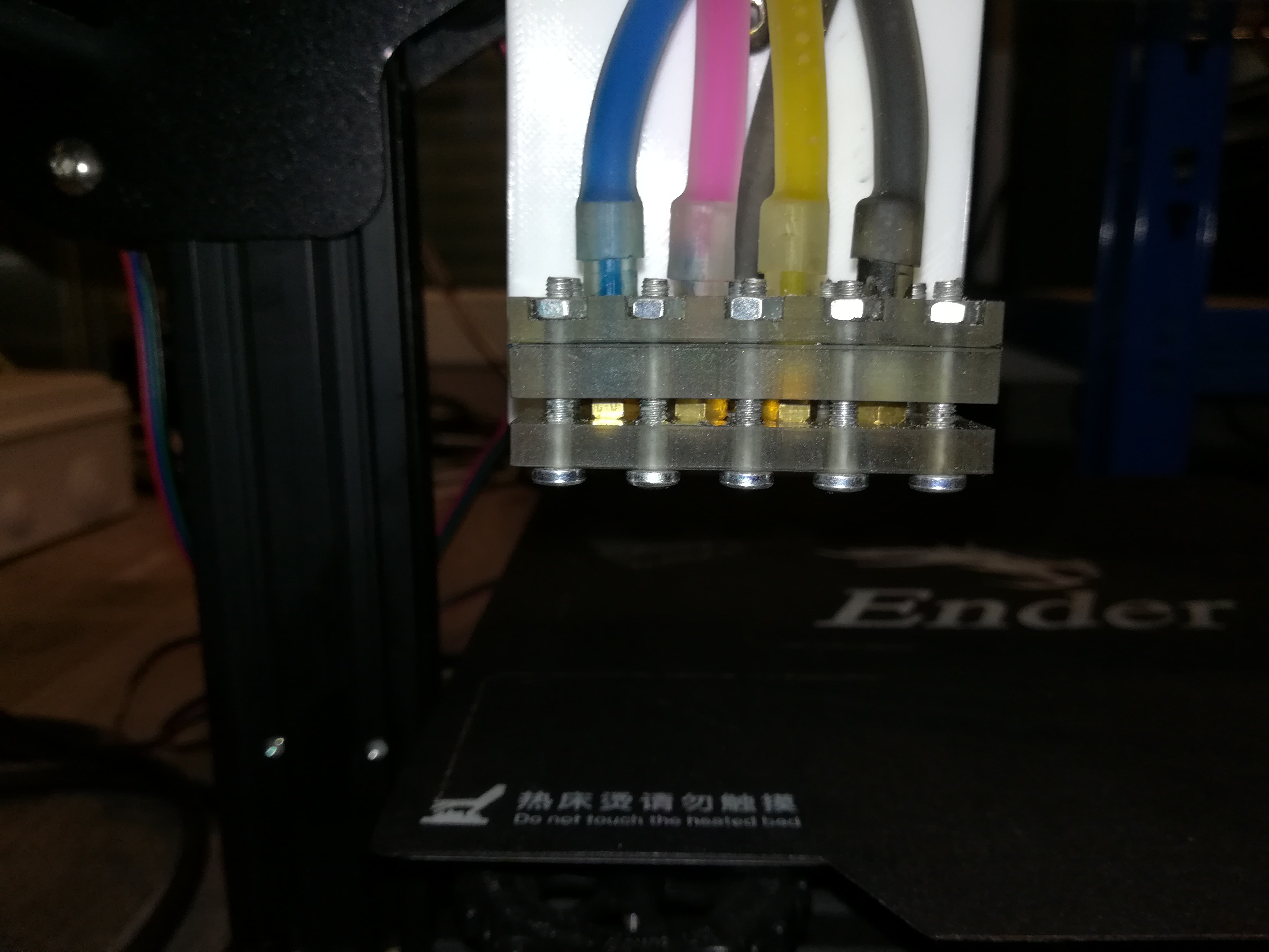
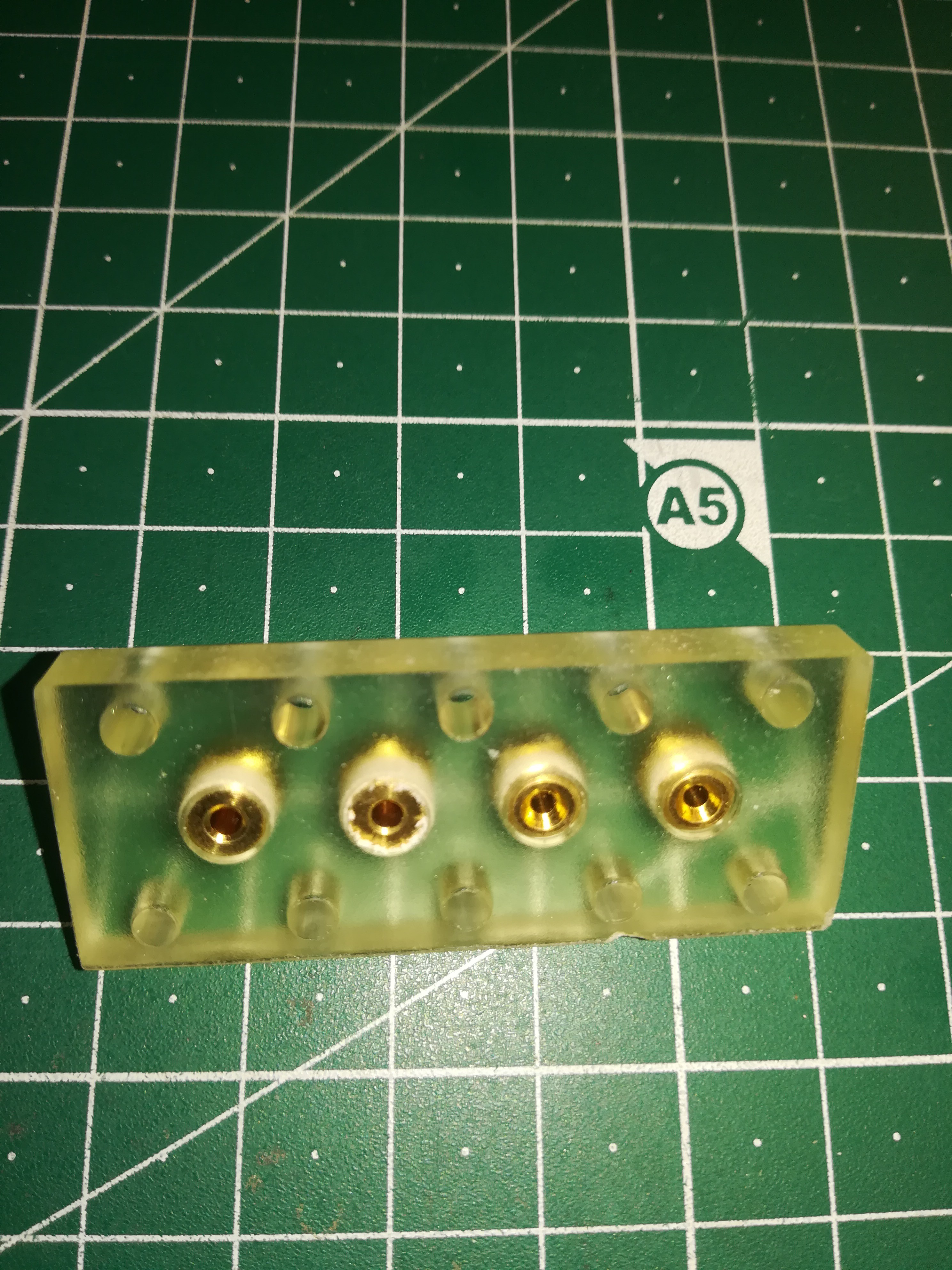
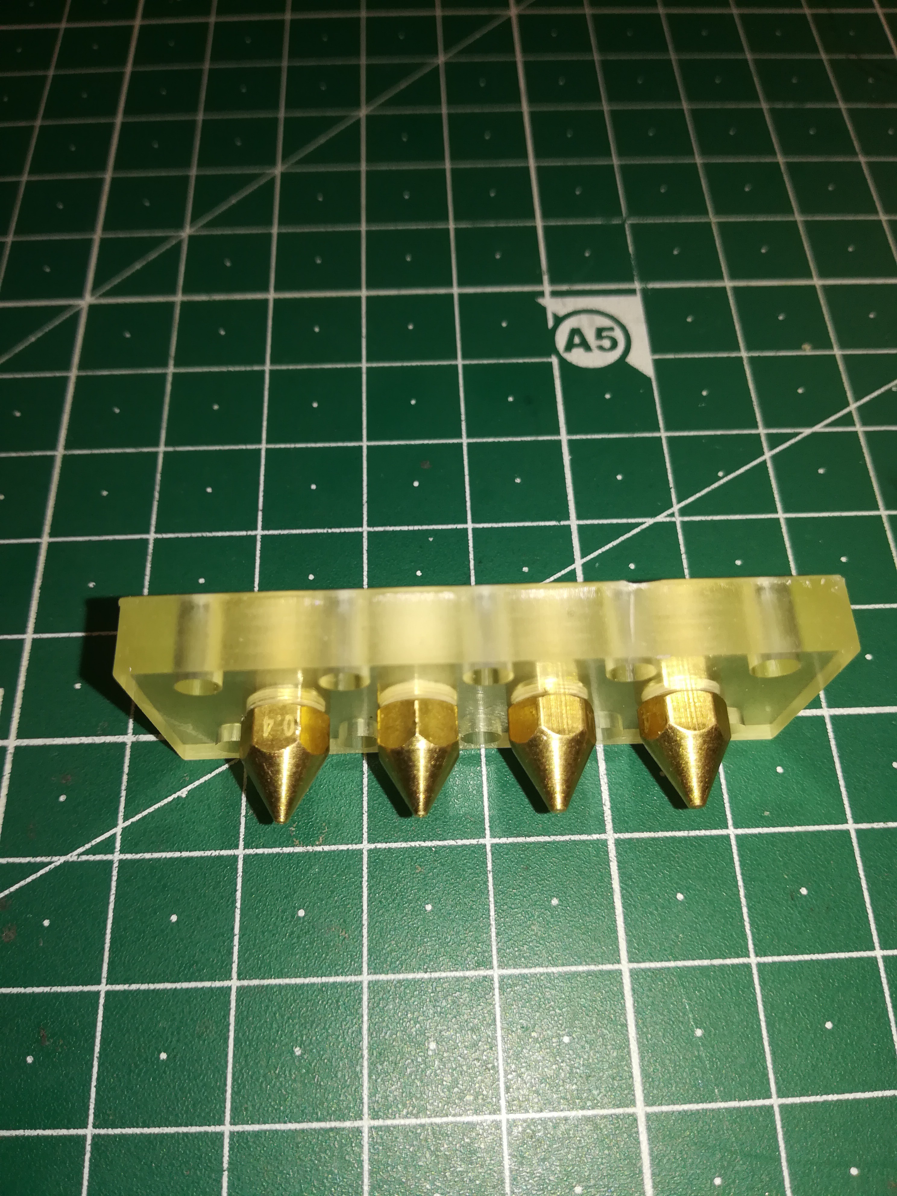
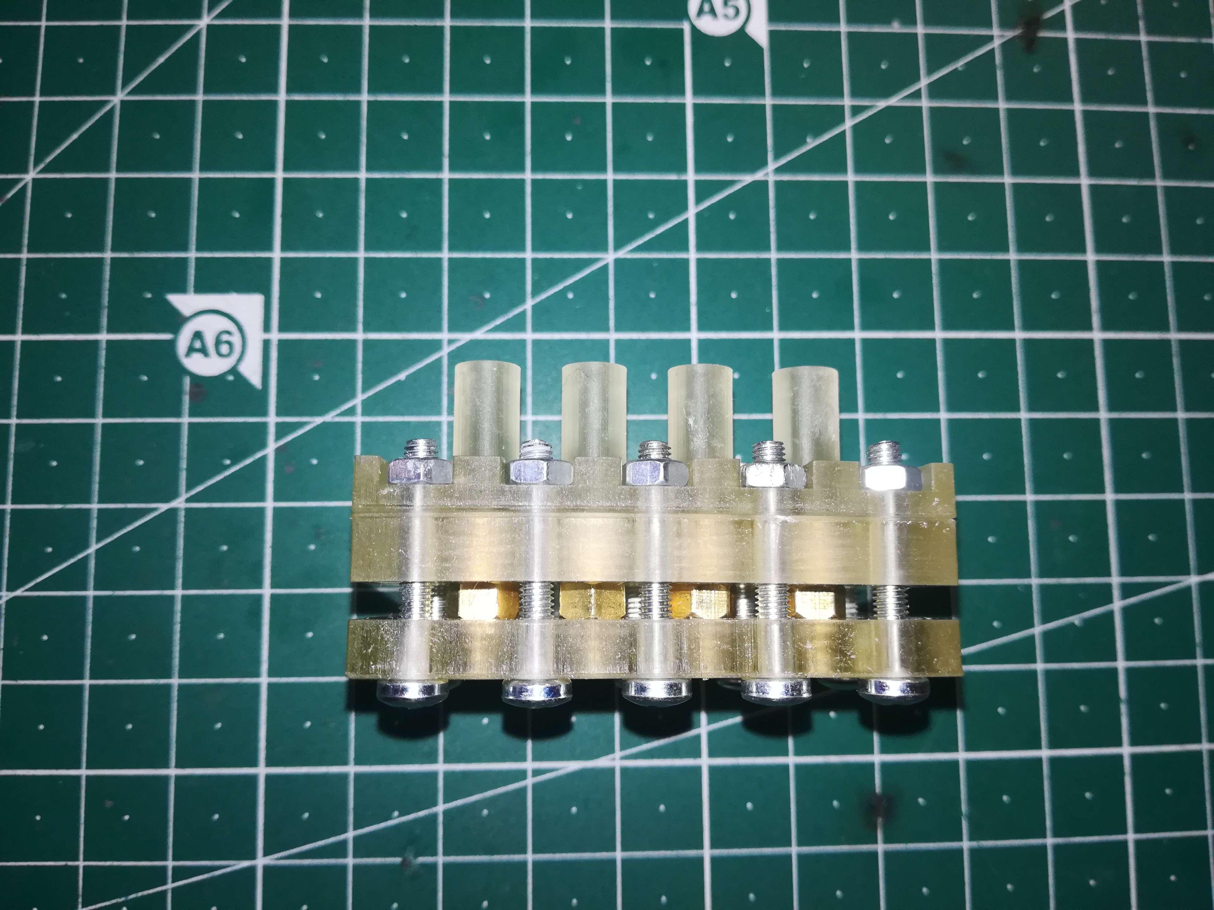
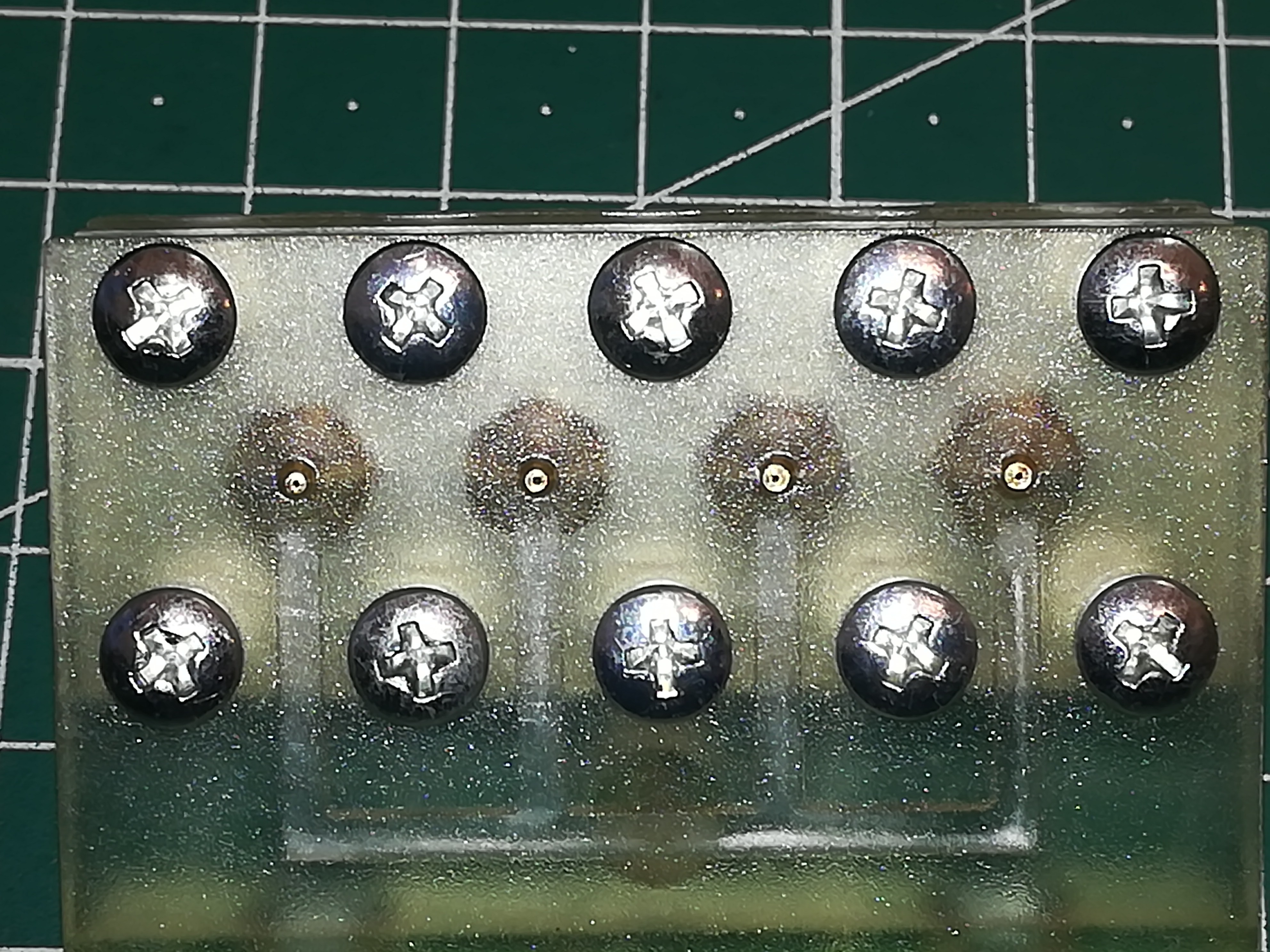
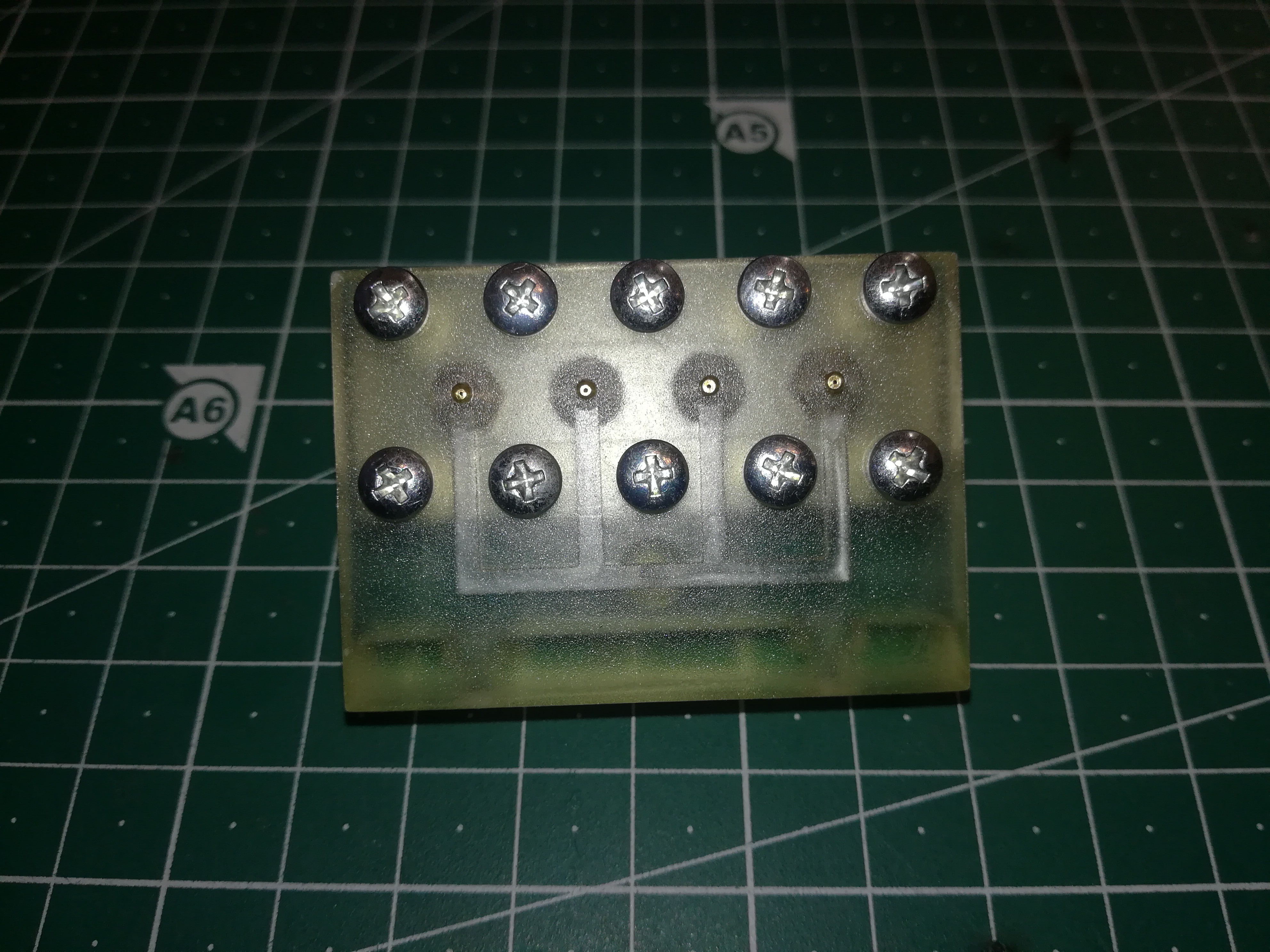
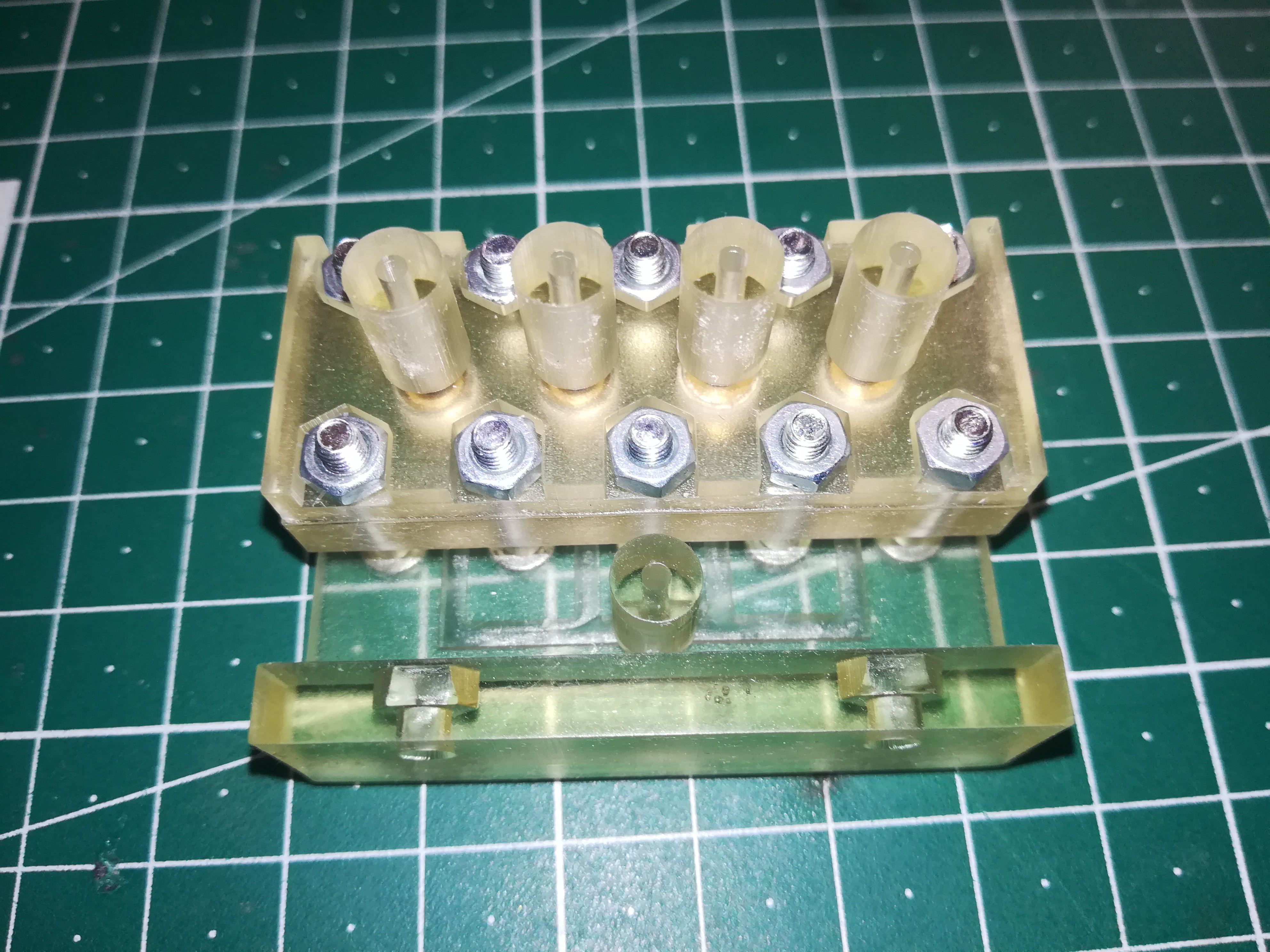
Assembling the Printhead
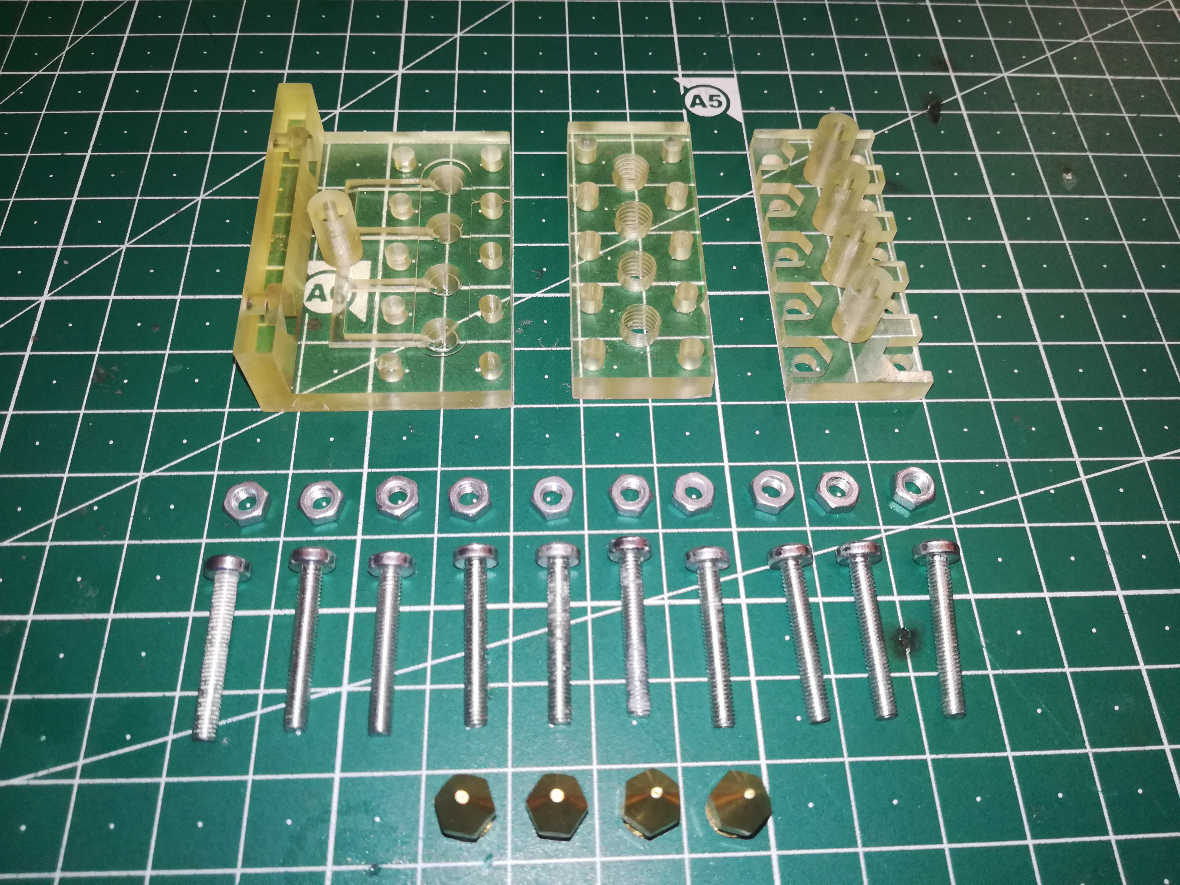
For the assembly of the printhead you need the following parts:
- printhead top
- printhead middle
- printhead bottom
- 10x M3x20 screws
- 10x M3 nuts
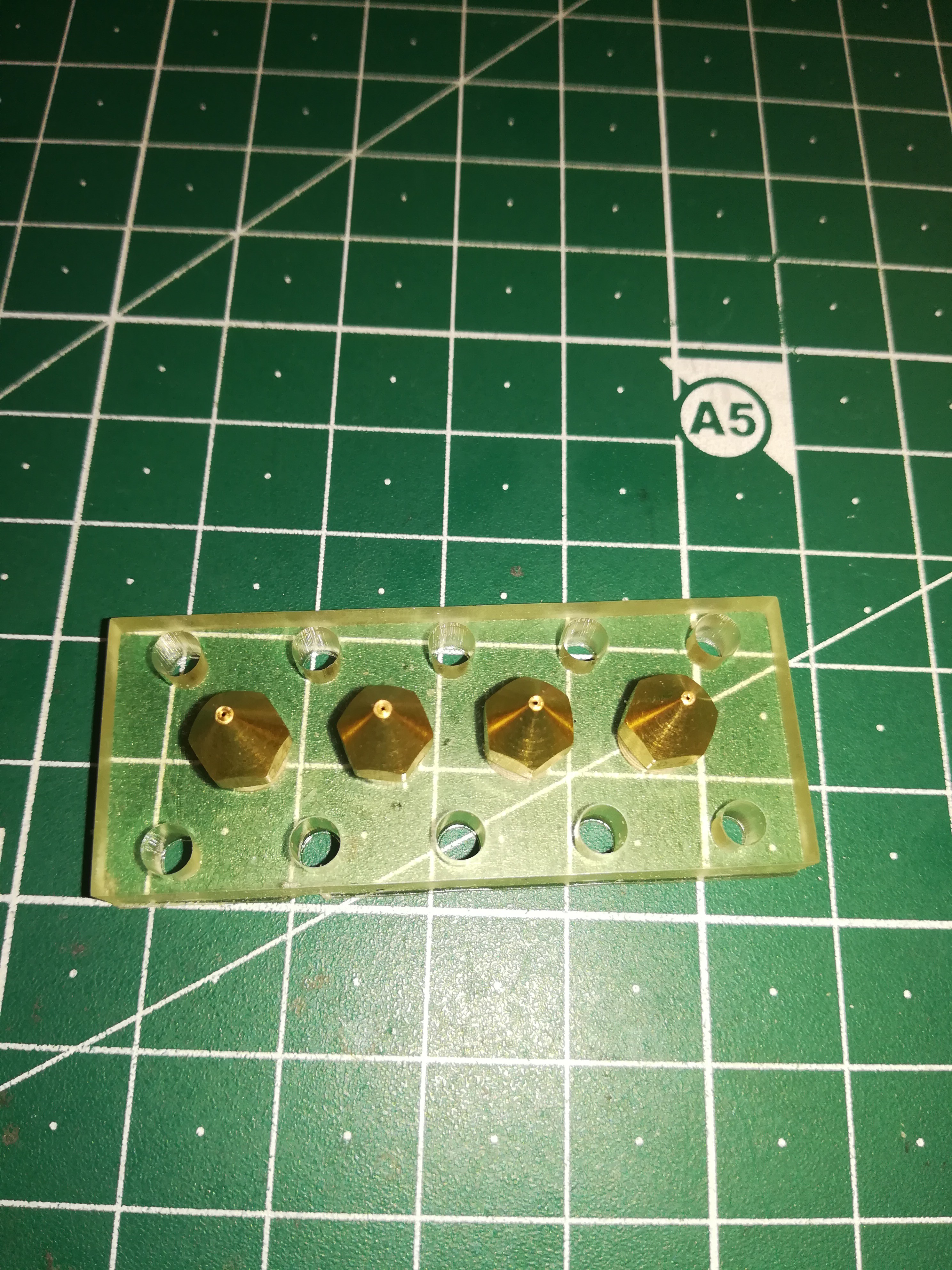
- 4x nozzle 0.2mm
I split the printhead in three parts for easier printing.
First you have to screw in the nozzles into the middle printhead part.
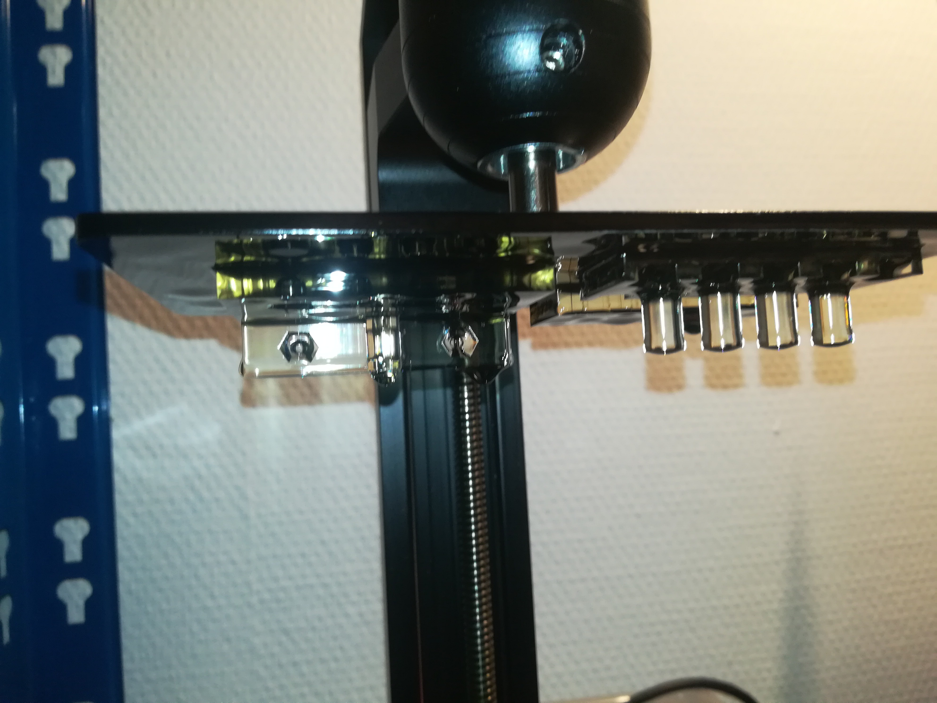
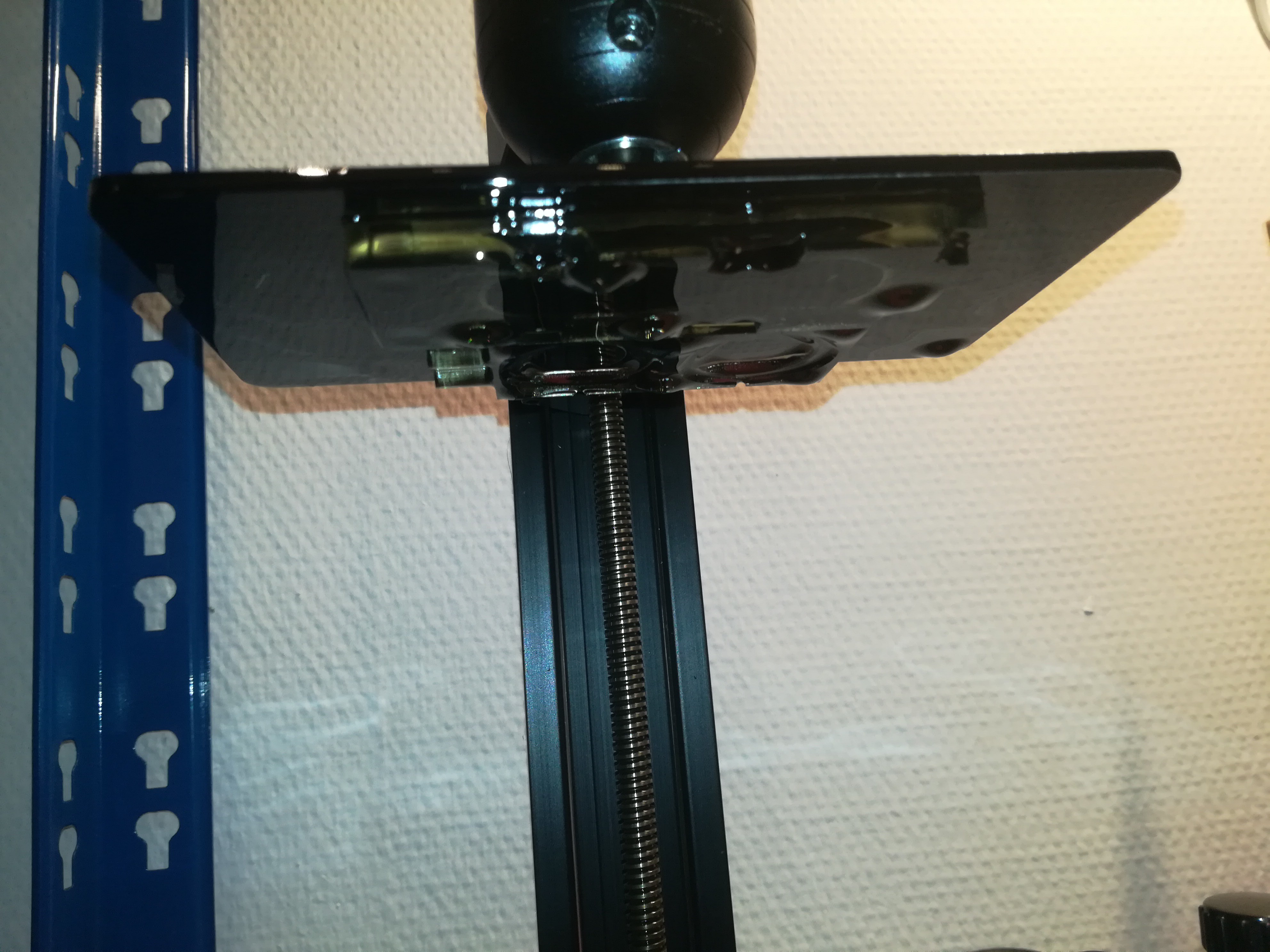
Now, you just have to stack the top onto the middle and the middle onto the bottom printhead part, place the nuts onto the top printhead part and screw in the screws through the bottom printhead part and you have finished the assembly.
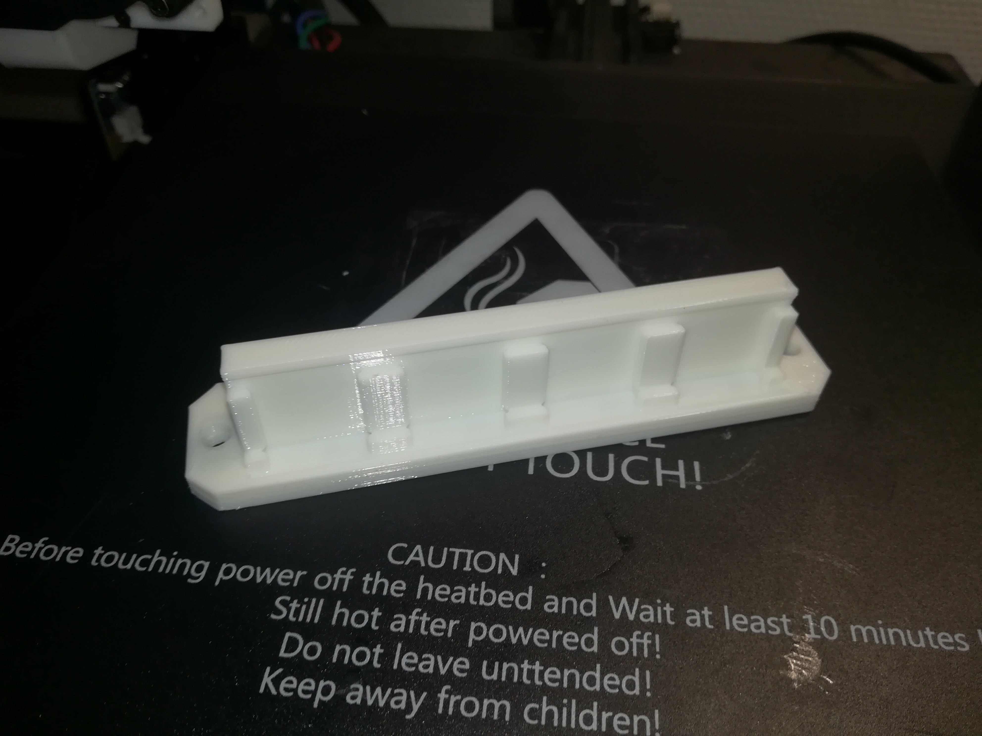
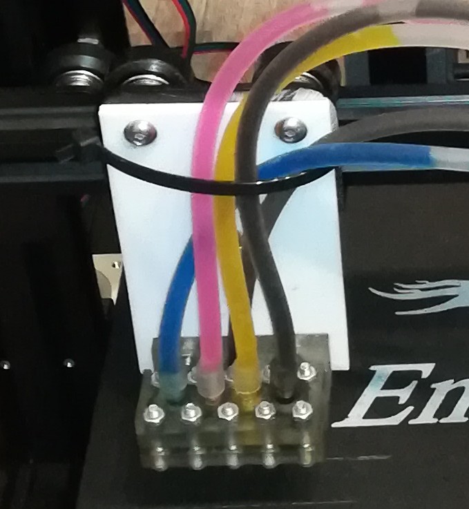
What's left to do is designing and printing your own printhead mounting bracket and fitting the printhead to your machine with two M3 screws and nuts.
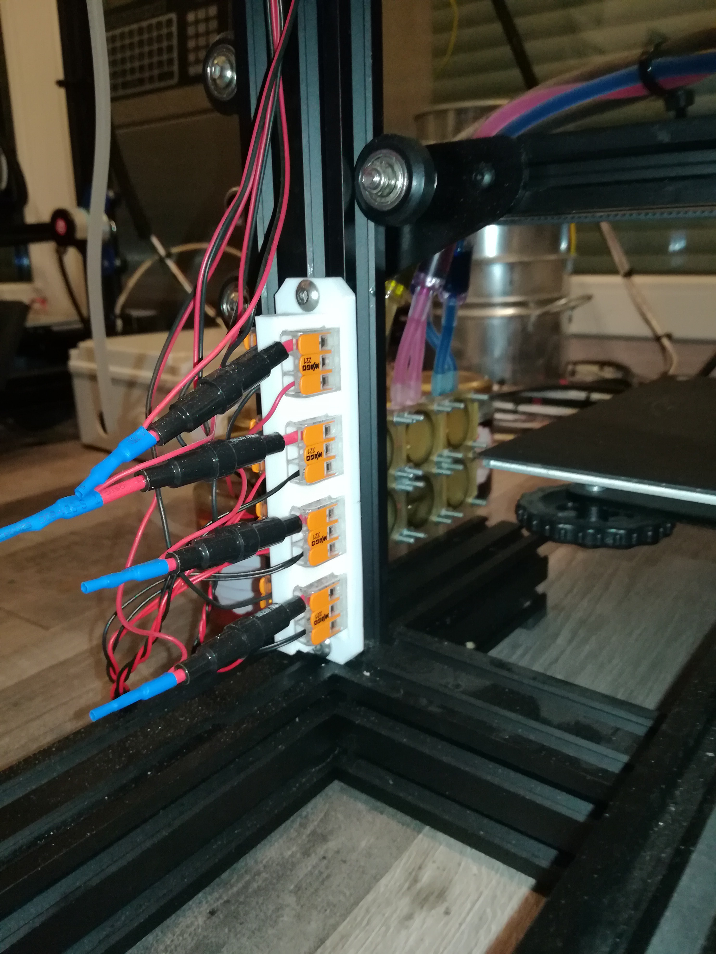
6
Assembling the WAGO Mounting Bracket
The purpose of the bracket with the WAGO 221-413 terminals is to be able to replace the piezo discs easily if they should stop working and for reversing the polarity if needed.
You just have to push in the WAGO 221-413 terminals with a pipe wrench and mount the bracket somewhere at the machine.
The design has a tight fit, so if you can not push in the terminals without breaking the printed part just print it a bit larger - or smaller if the terminals sit too loose.
Every pump has a fuse to protect the electronics in the case a piezo pump would get shorted out because of leaking. For these I used the smallest value fuse I could find because the piezo discs need only a very small current for operation.
7
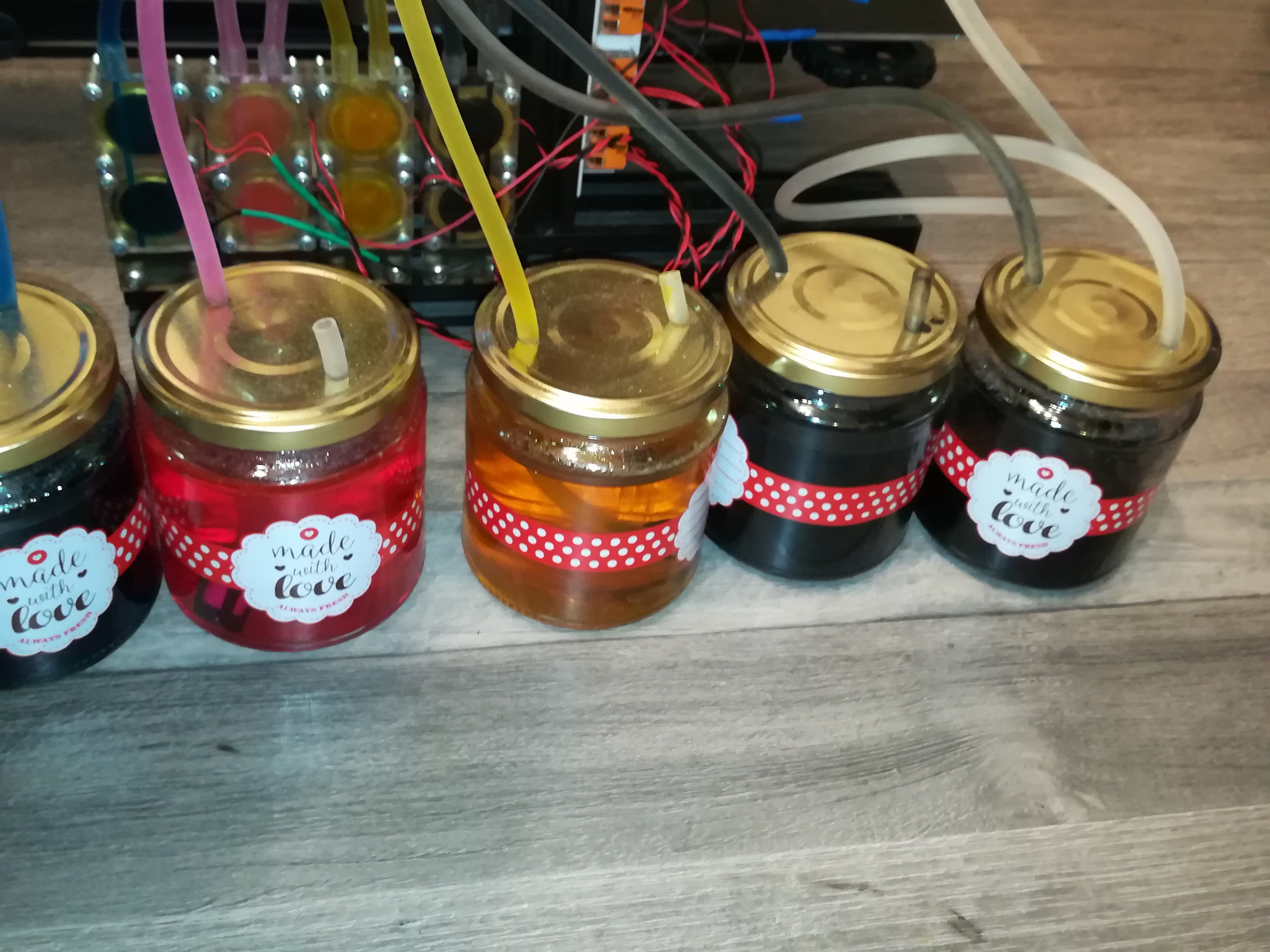
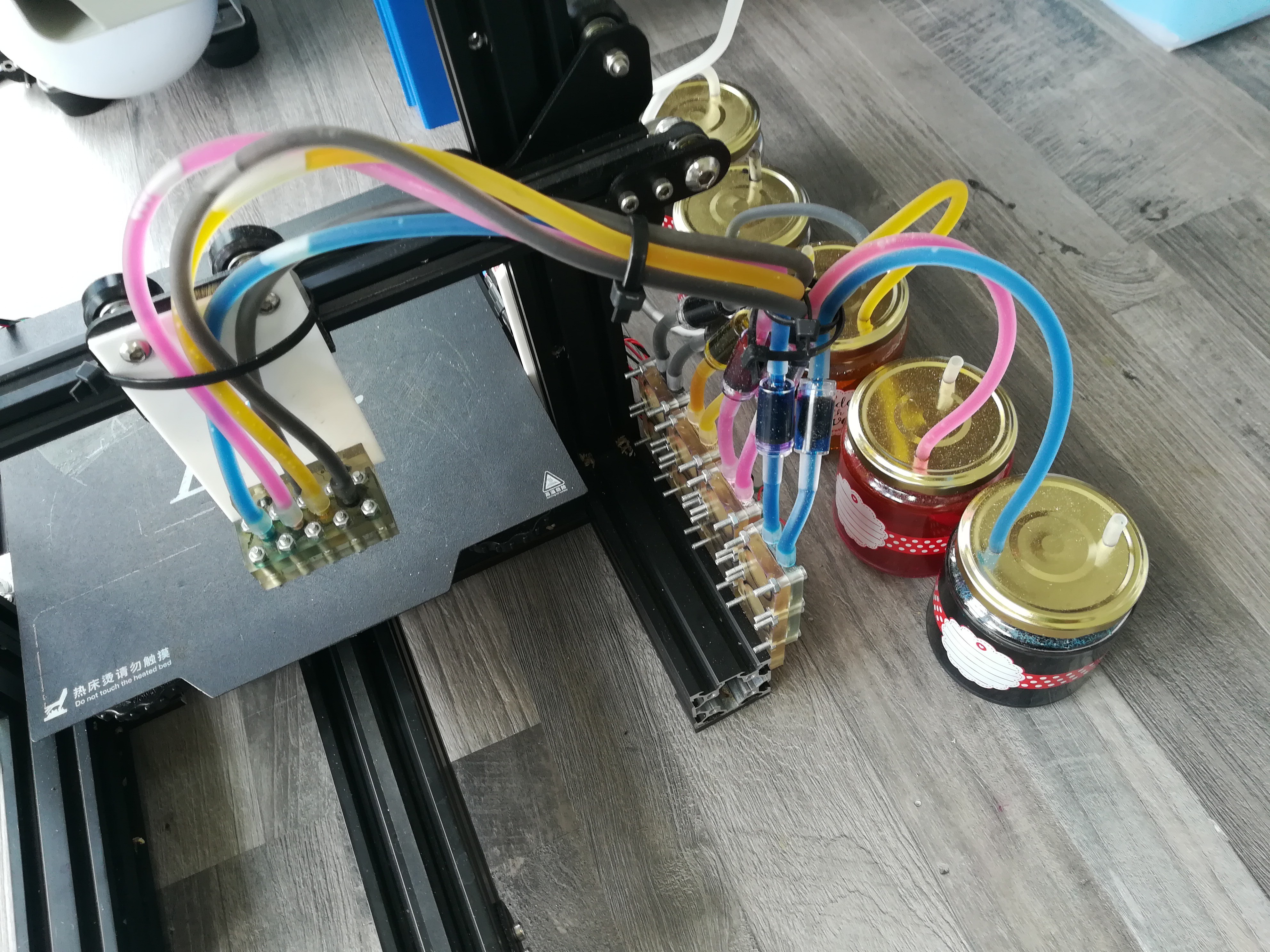
Ink and Waste Container
If you use four colors you will need four ink containers and one waste container.
I used some empty jelly jars for that and drilled two 5mm holes into the lid to fit in the 6mm silicone tube.
At the ink containers one tube is connected to the piezo pump and the other one is just there to prevent the buildup of vacuum and for adding ink.
At the waste contsiner one tube is connected to the vacuum duct at the printhead and the other one is connected to a small 12V vacuum pump. Its purpose is to draw the excess ink from the nozzles into the waste container, because it
would otherwise form a drop which would block the nozzle until it drops down on the workpiece.
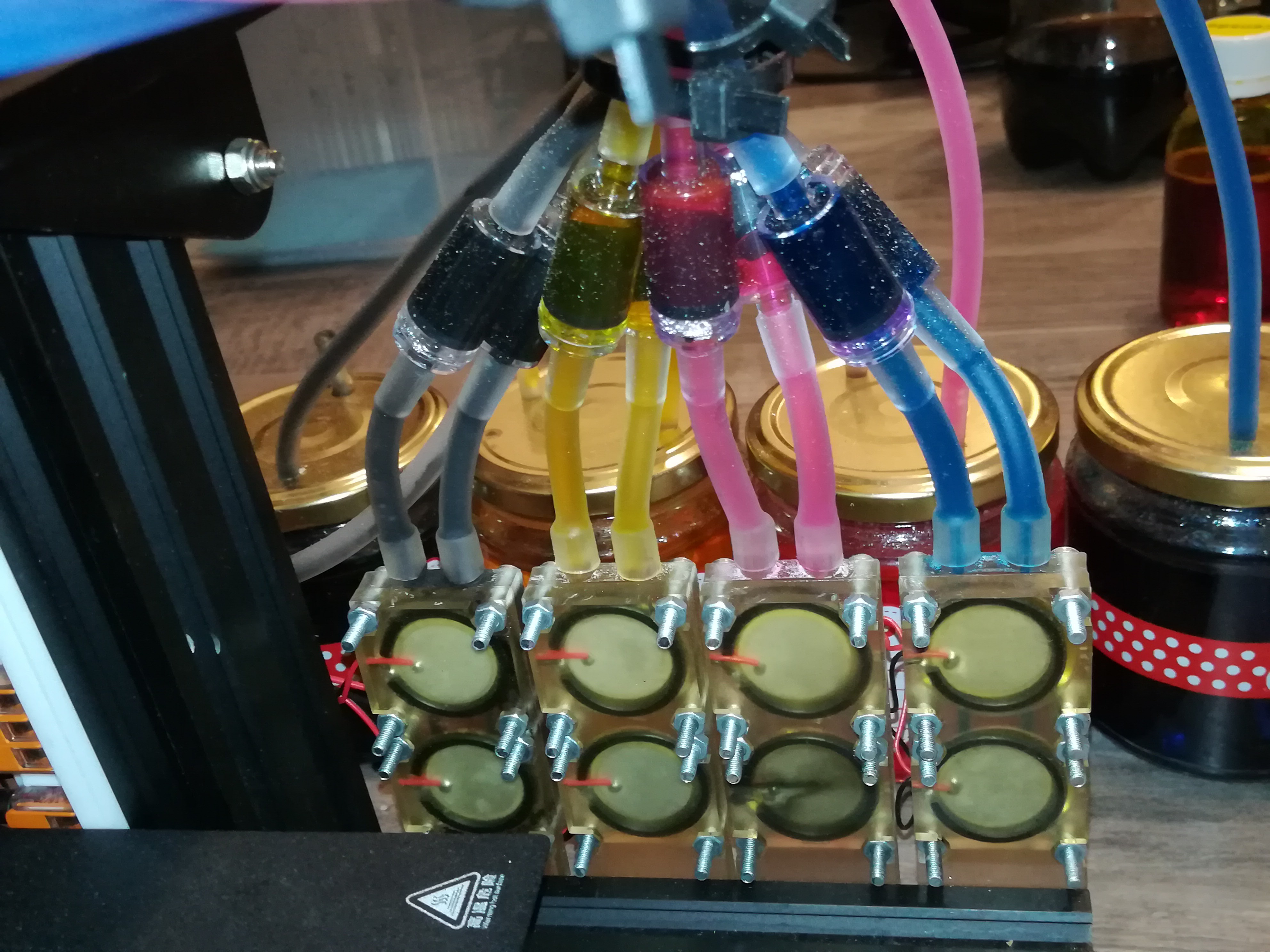
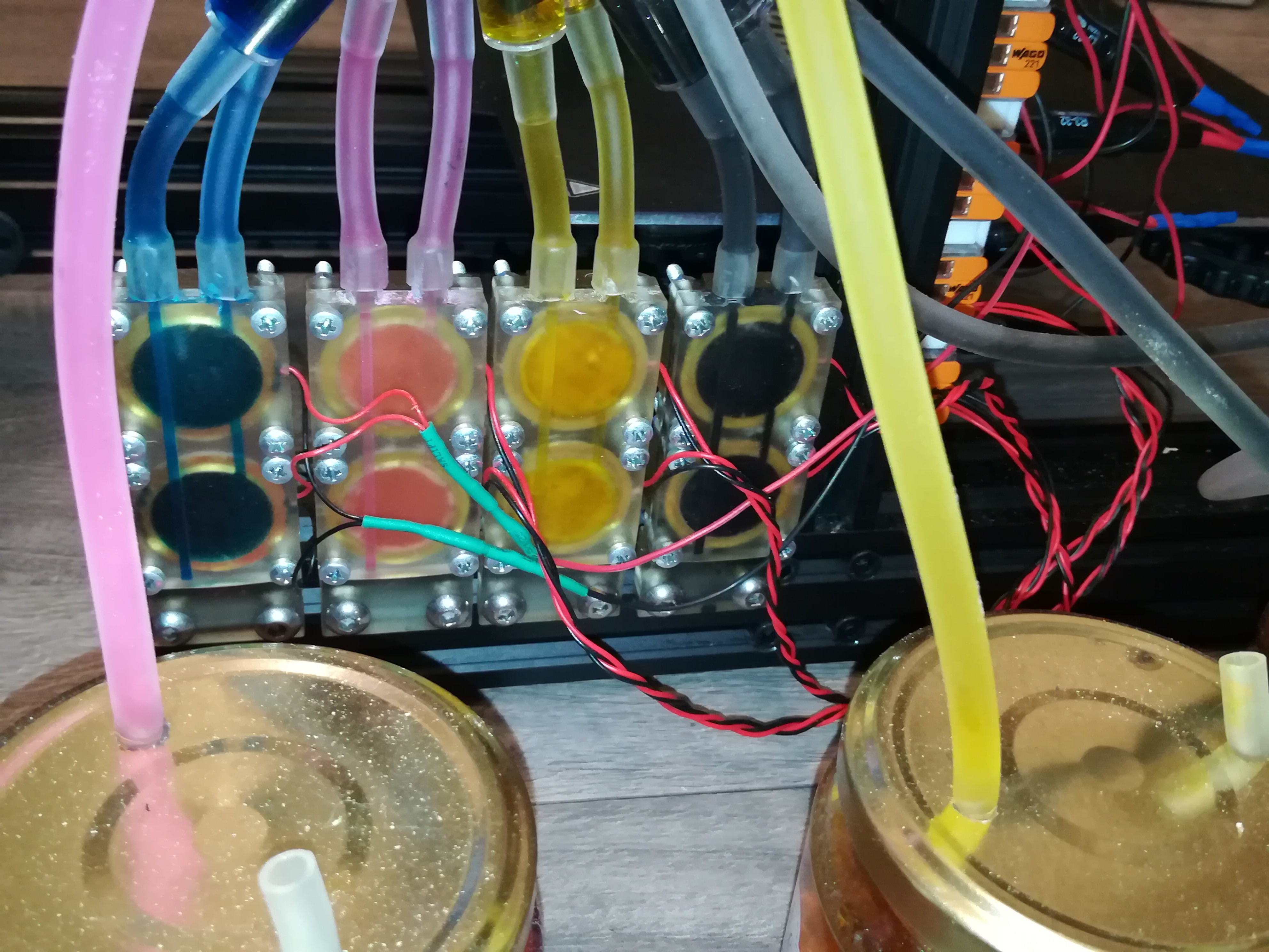
8
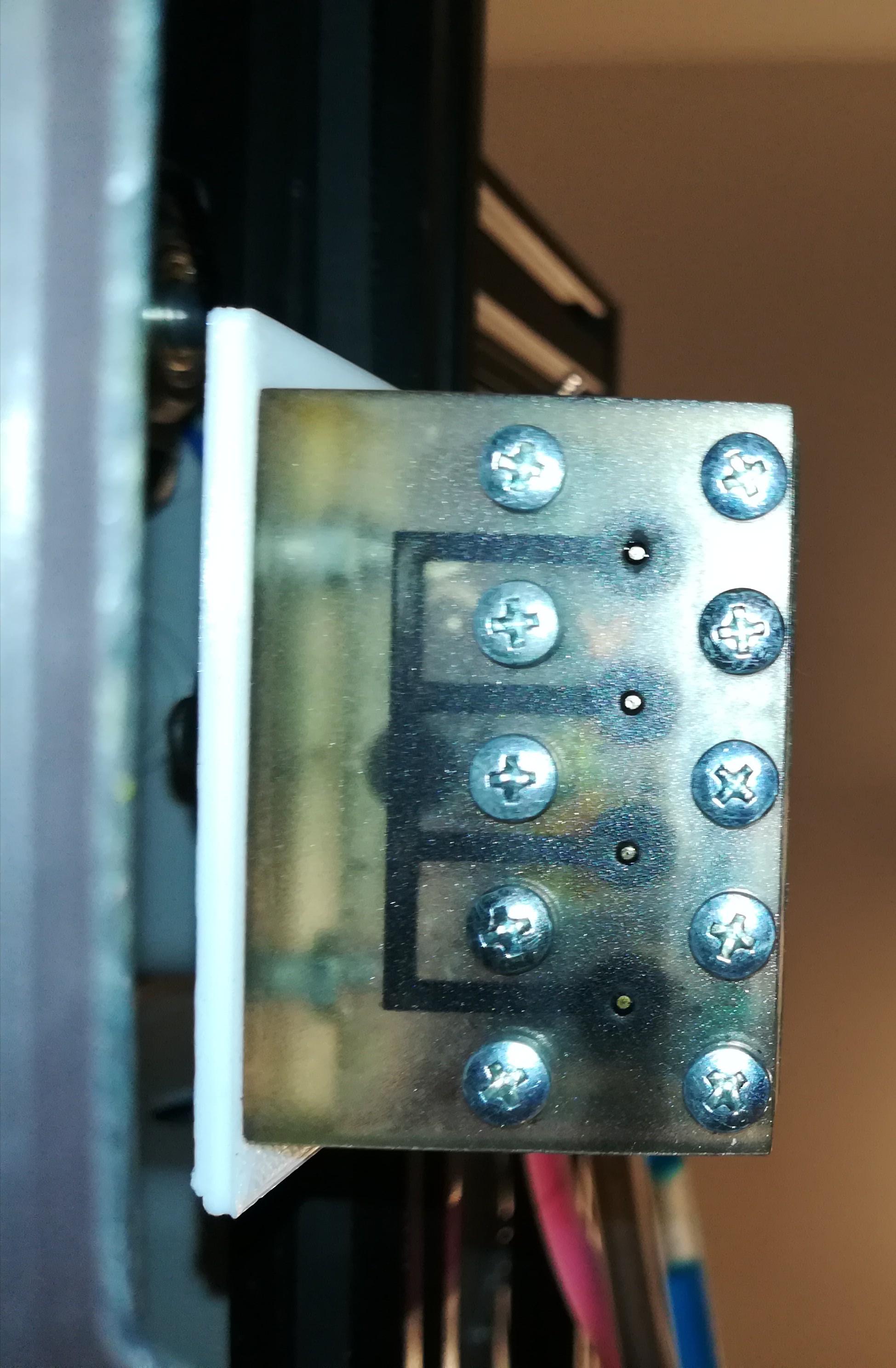
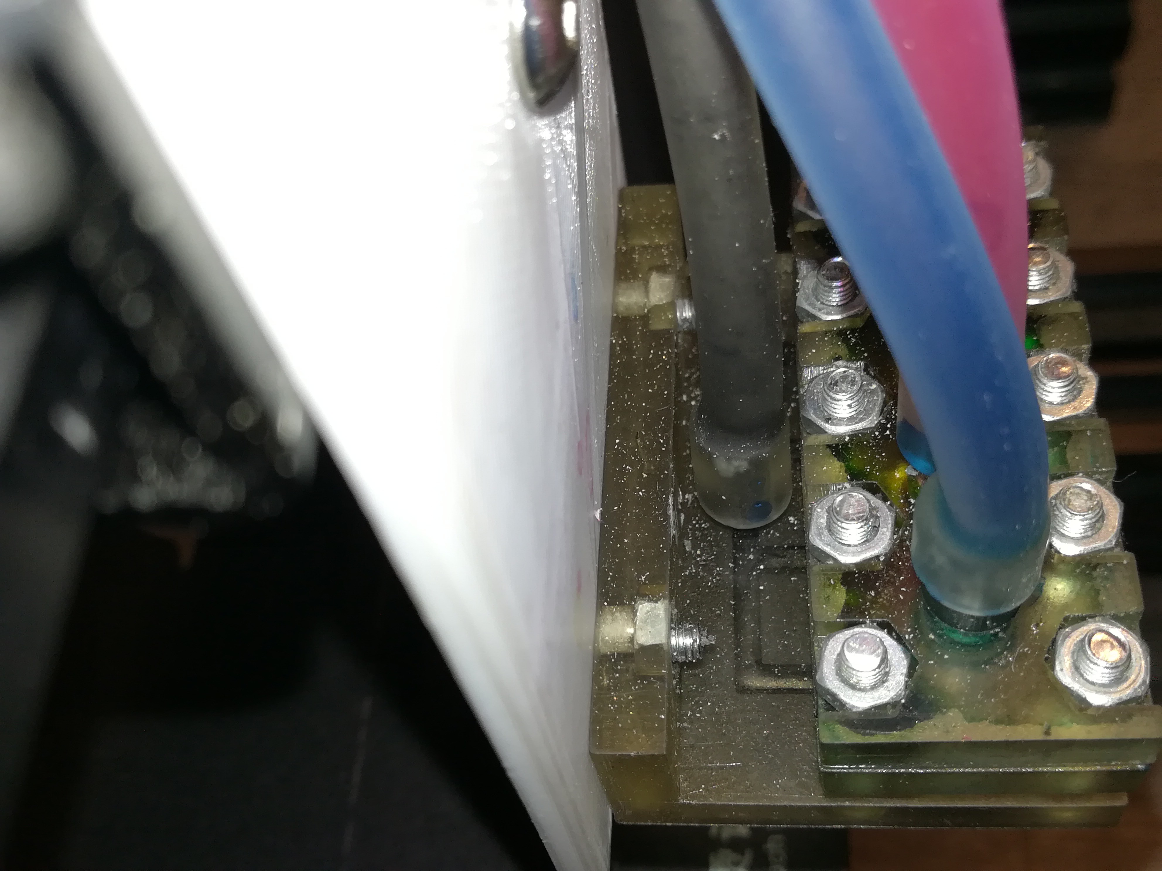
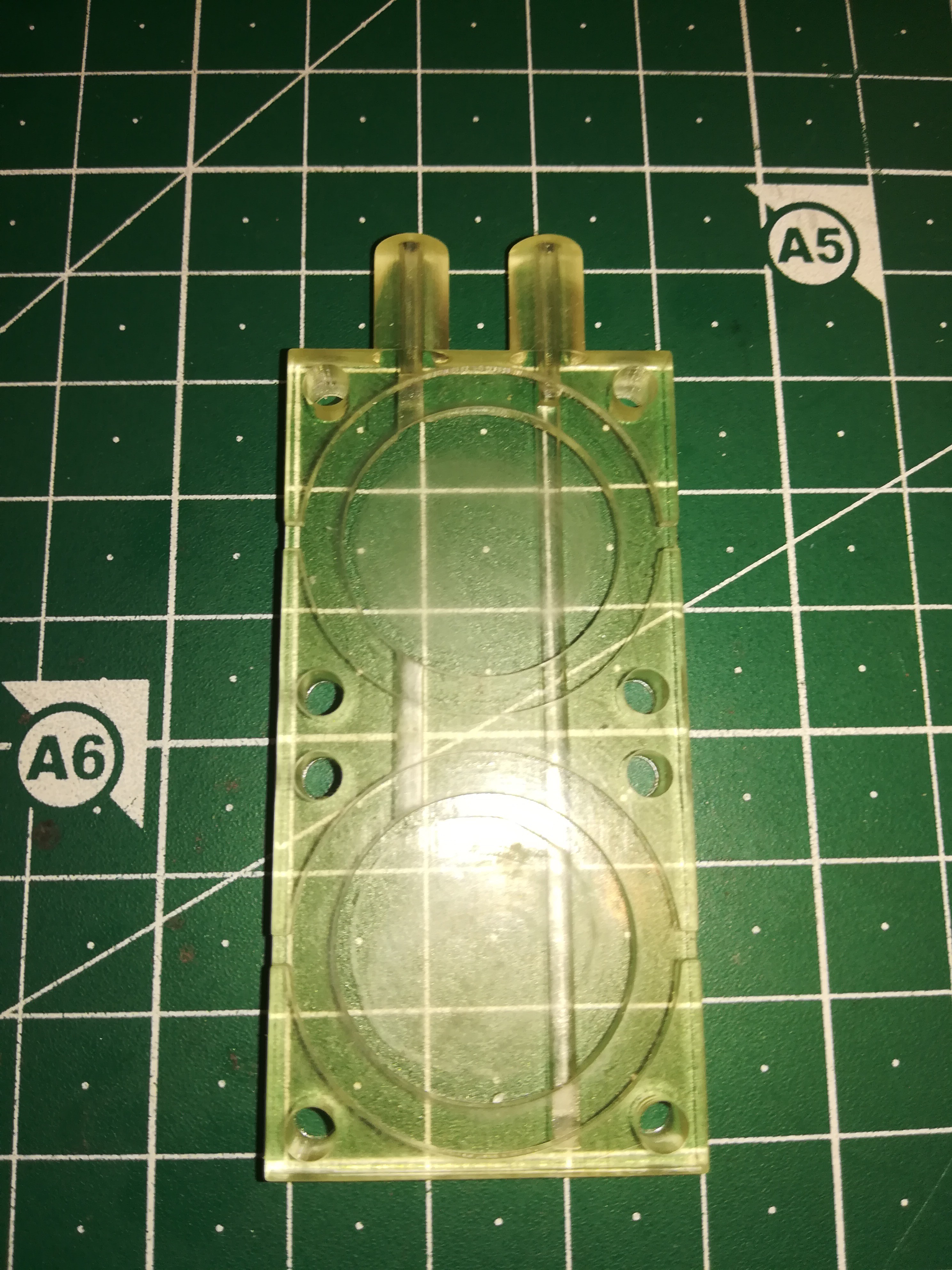
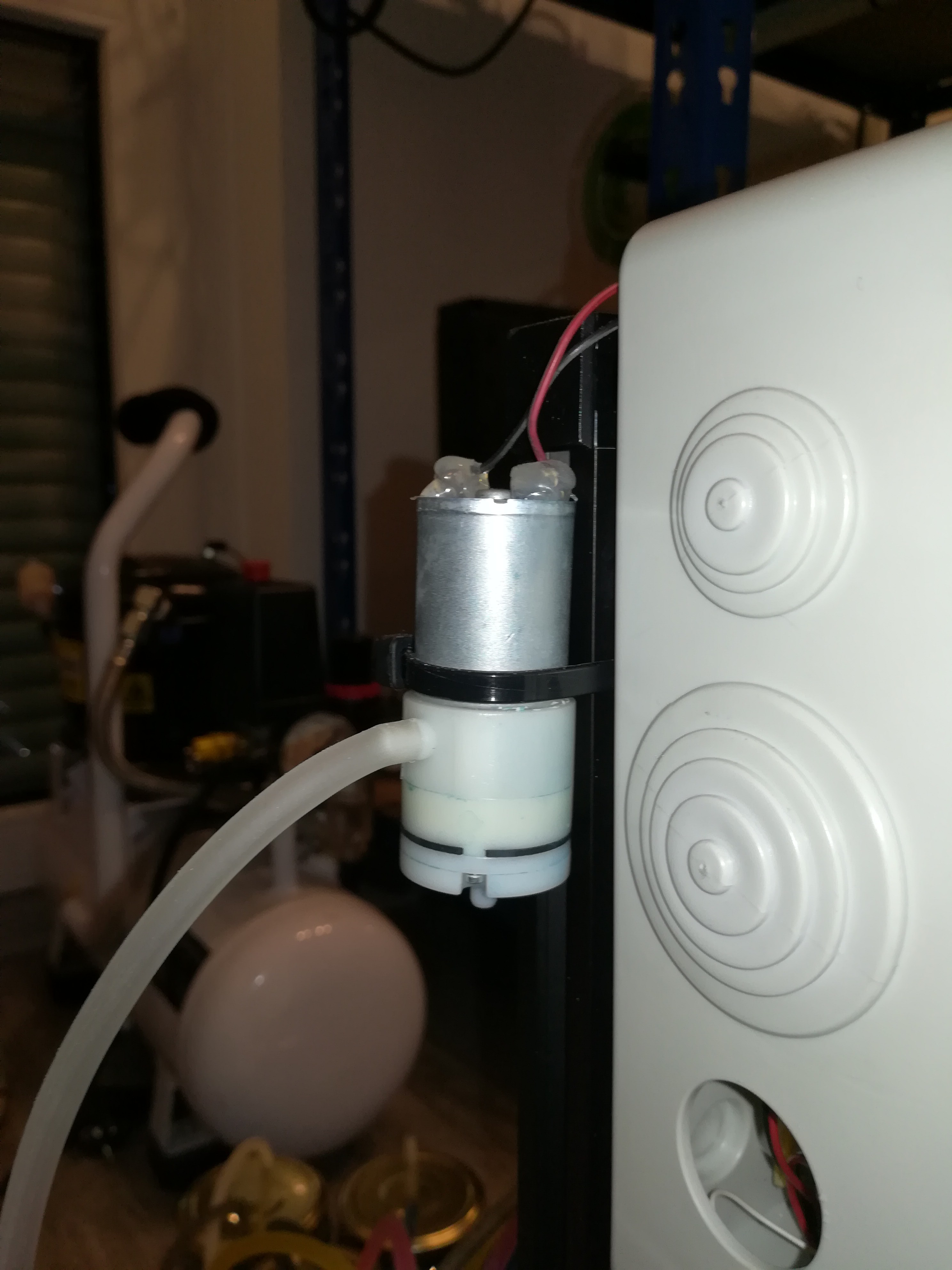
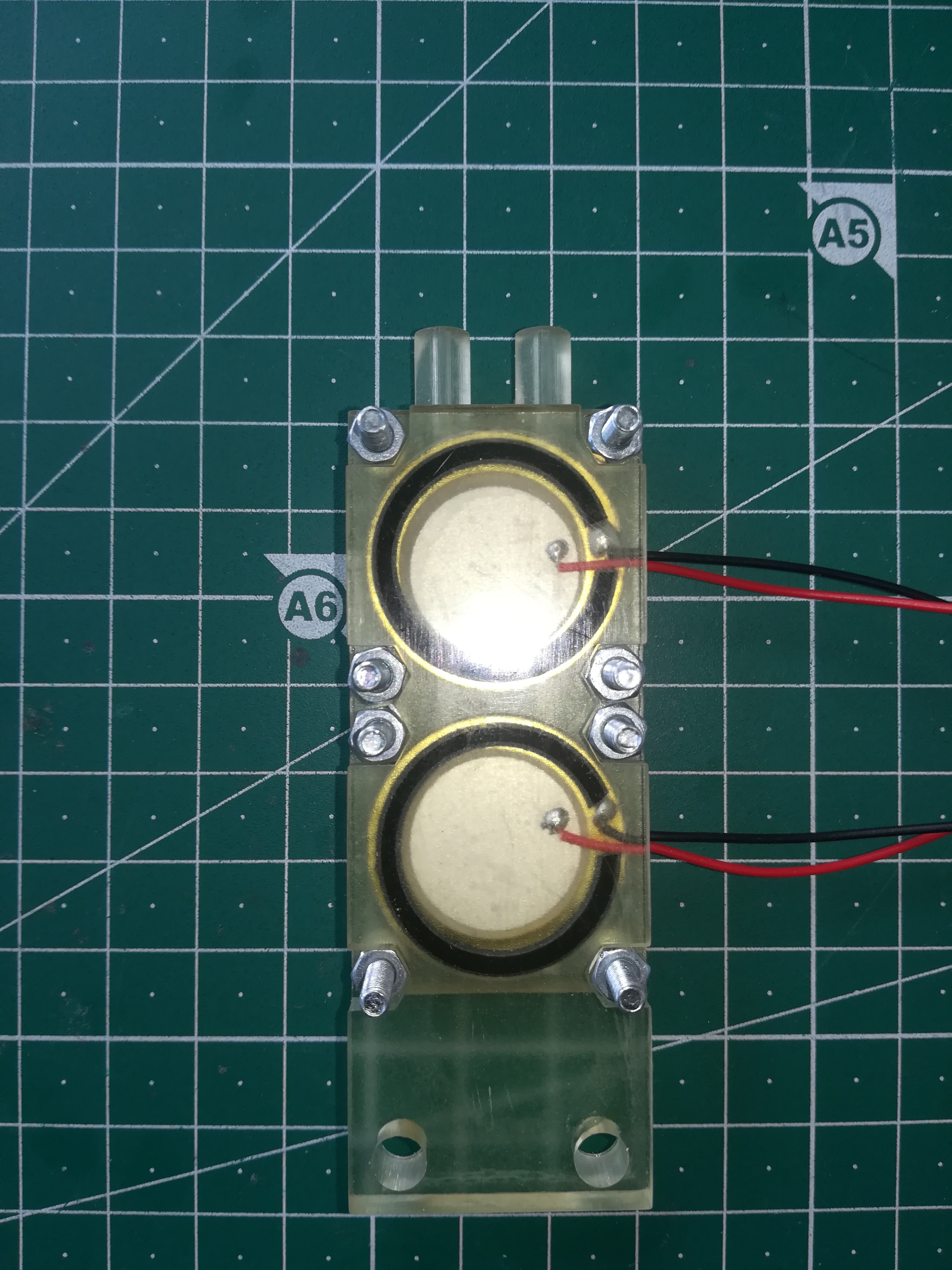
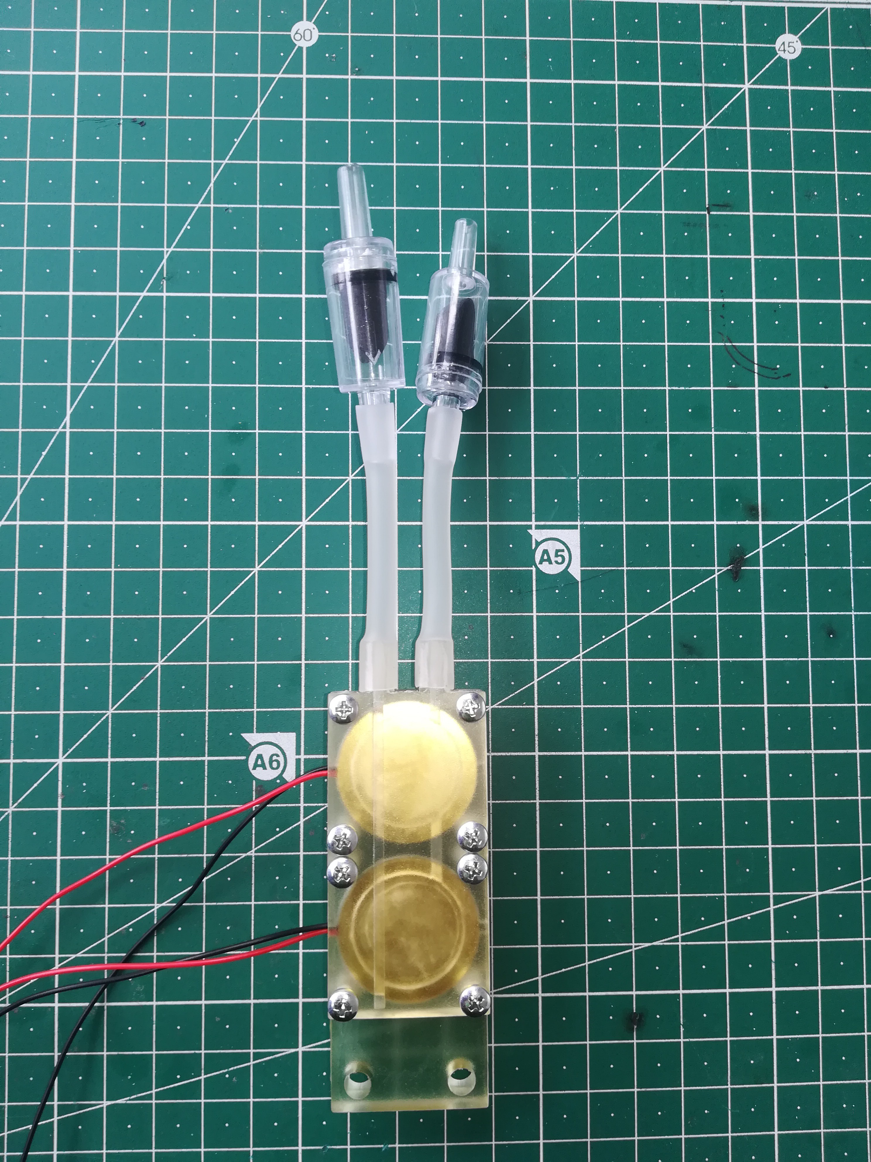
Assembling the Piezo Pumps
The heart of the machine are the four piezo pumps which are made of the following parts:
- piezo pump body
- piezo pump cover / mounting bracket
- 8x M3x20 screws
- 8x M3 nuts
- 2x O - ring 21x25x2mm
- 2x 27mm piezo disc
- 2x check valve
- petrol filter
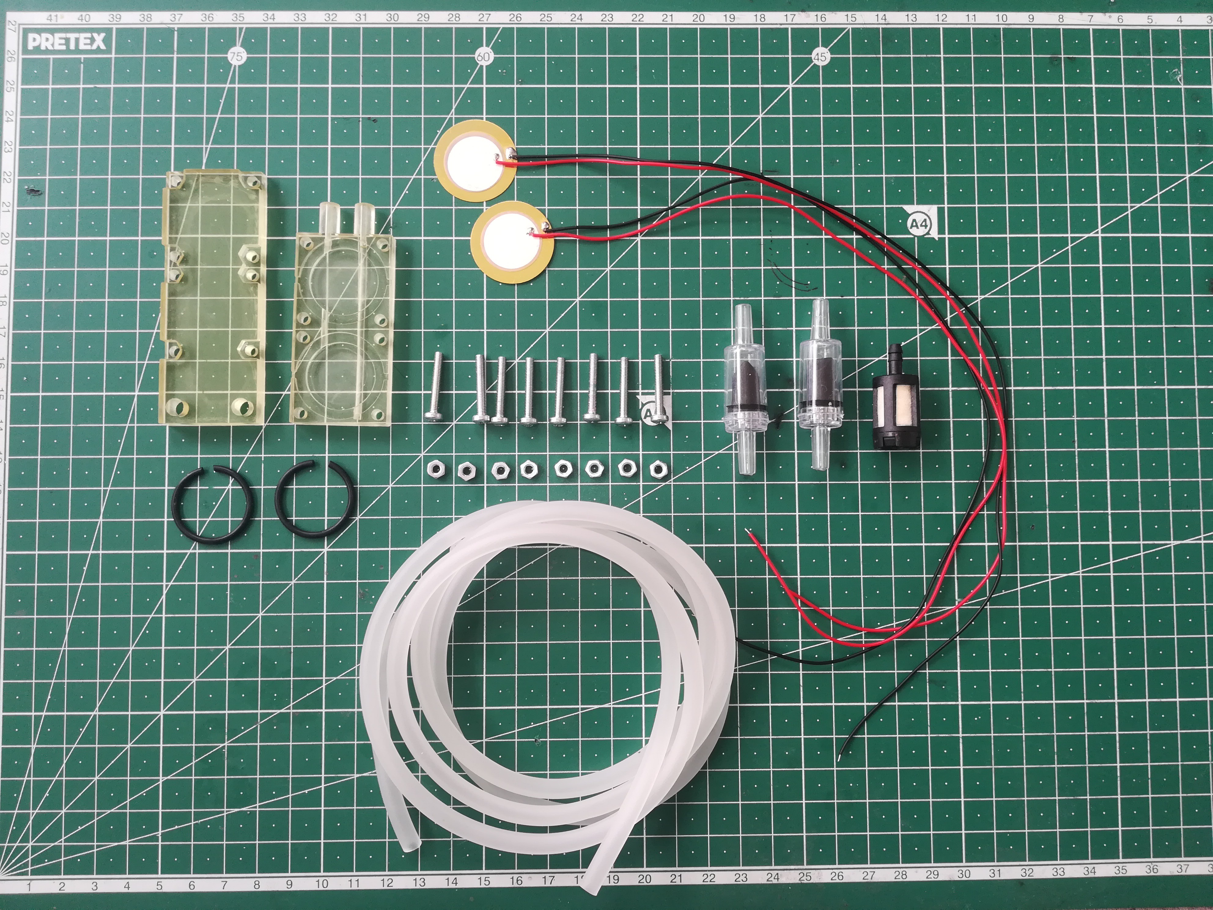
- 6mm silicone tubing
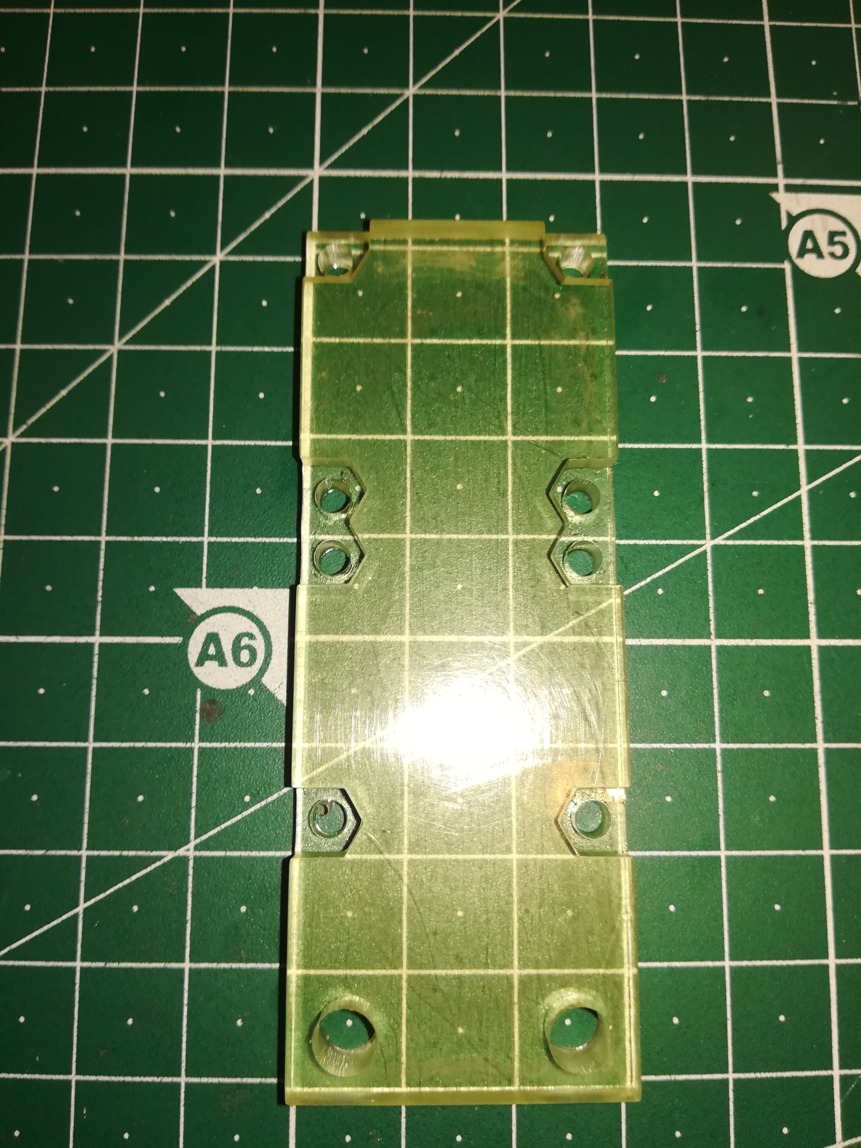
First, insert the screws from the bottom through the pump body and place the piezo discs with the O - ring in the pump chambers (cut out a piece of the o - ring for the solder connection on the piezo).
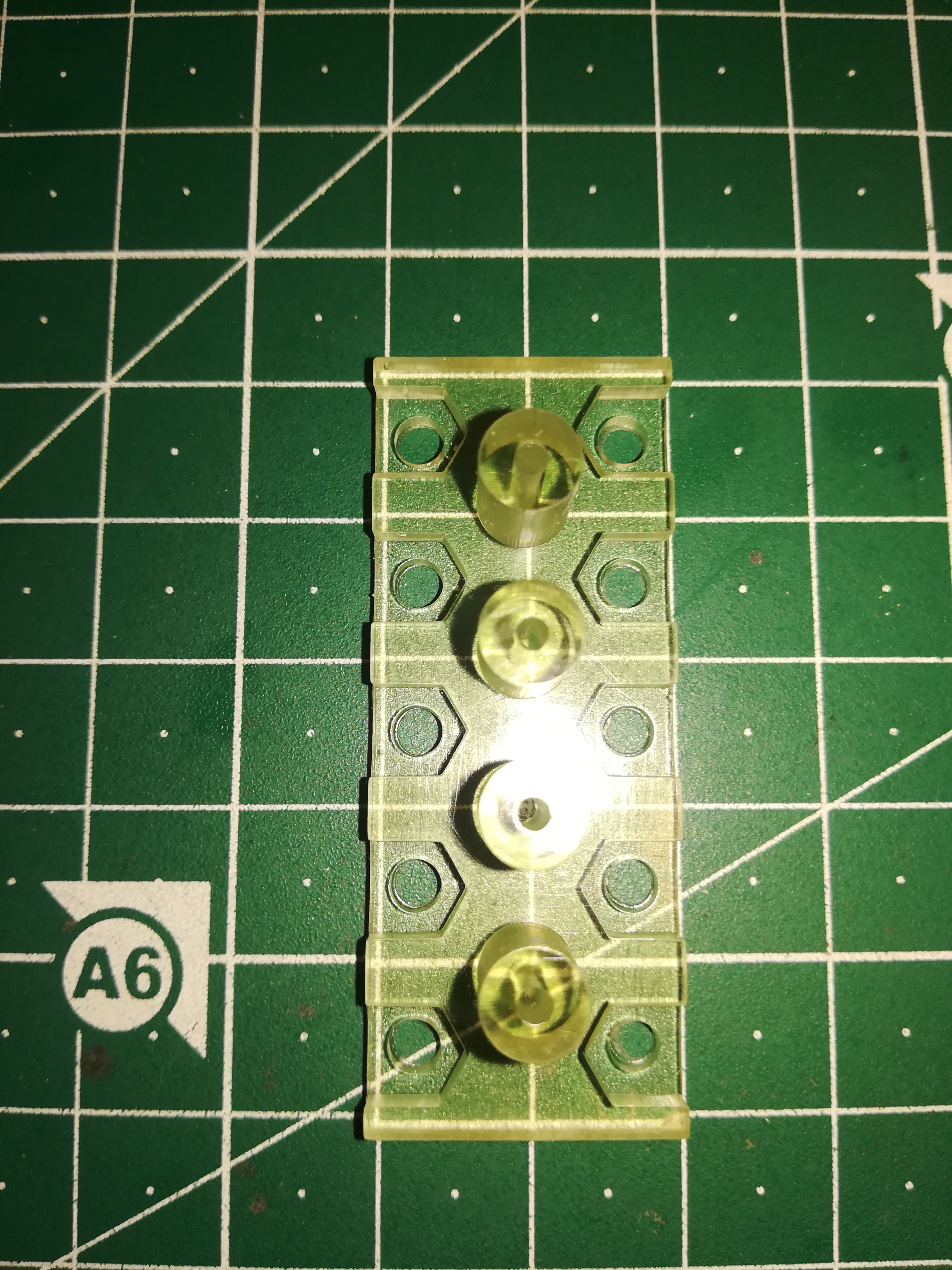
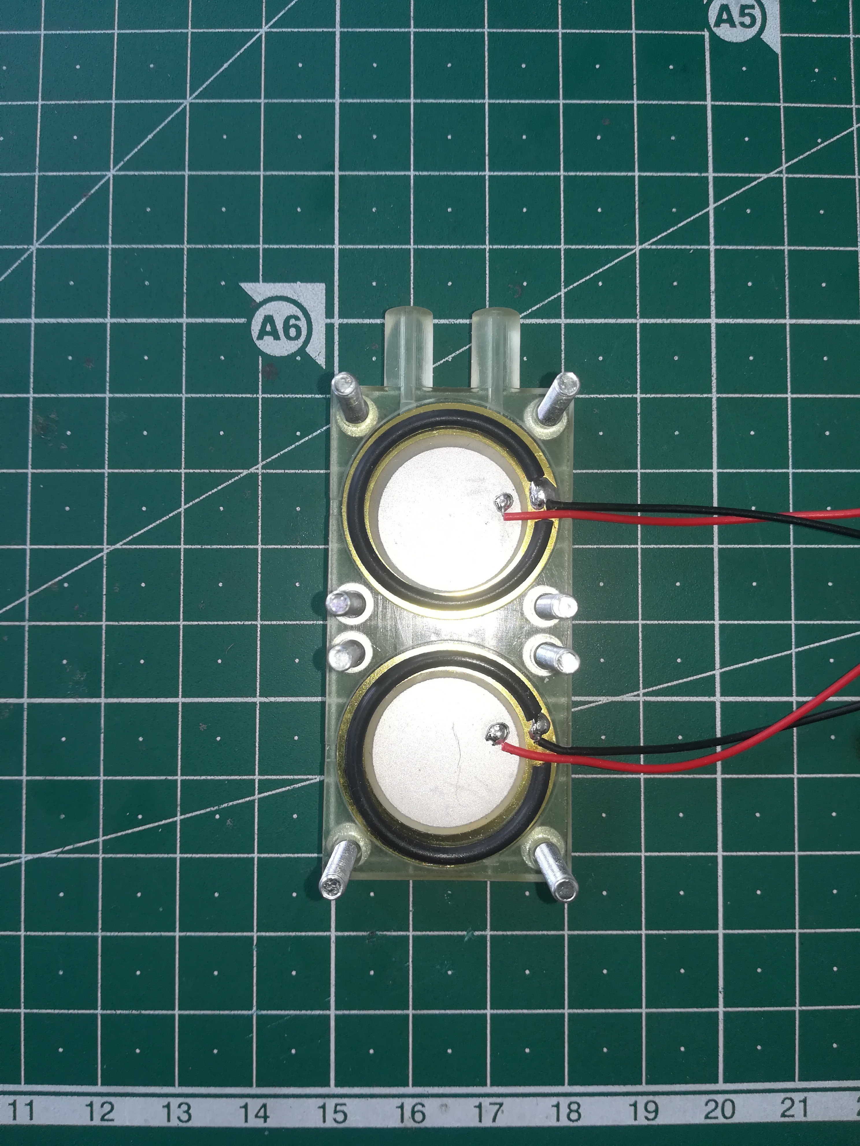
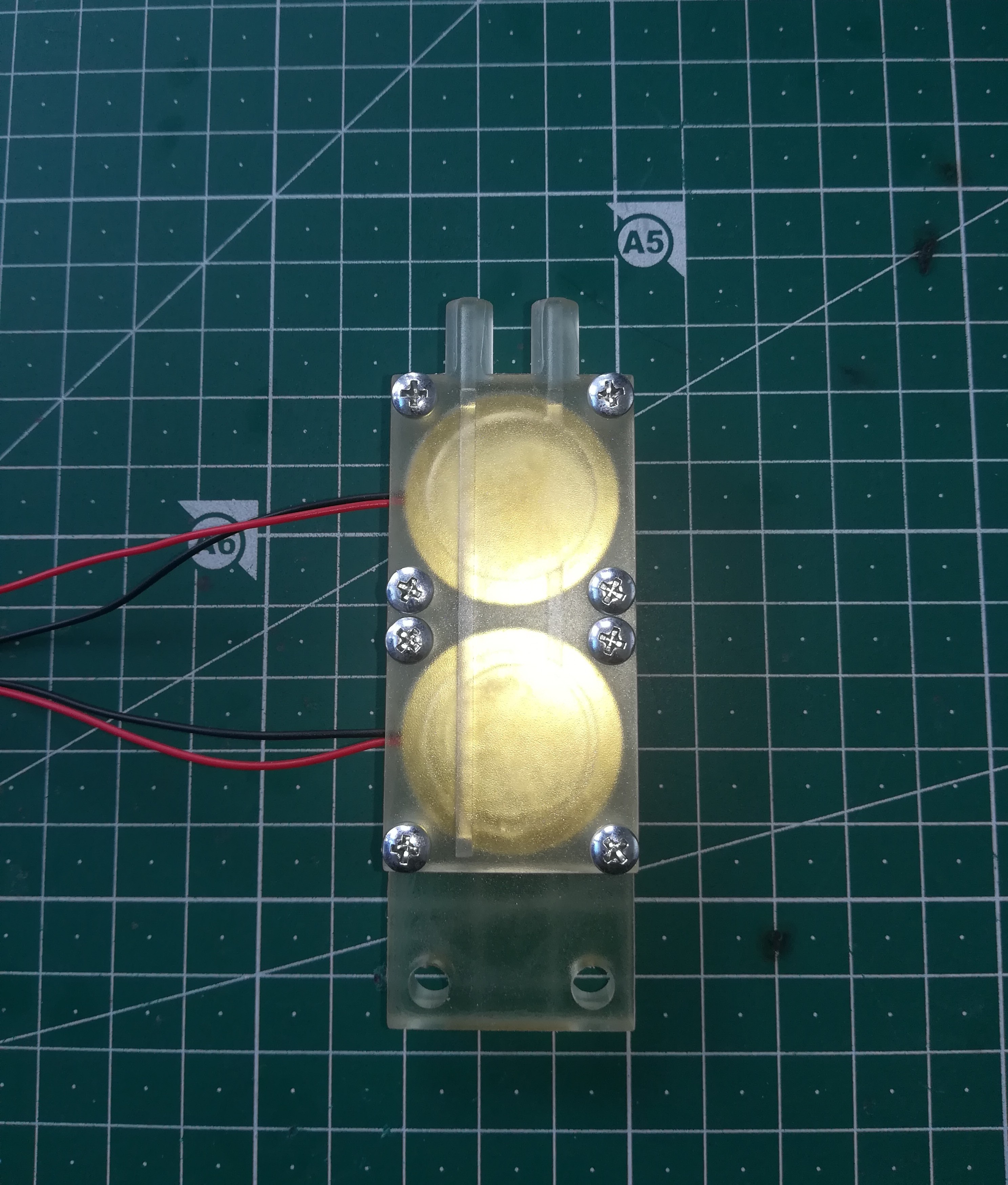
Put the pump cover on top of it...
and put the nuts onto the scews. Then carefully lift the parts and tighten the screws from the bottom.
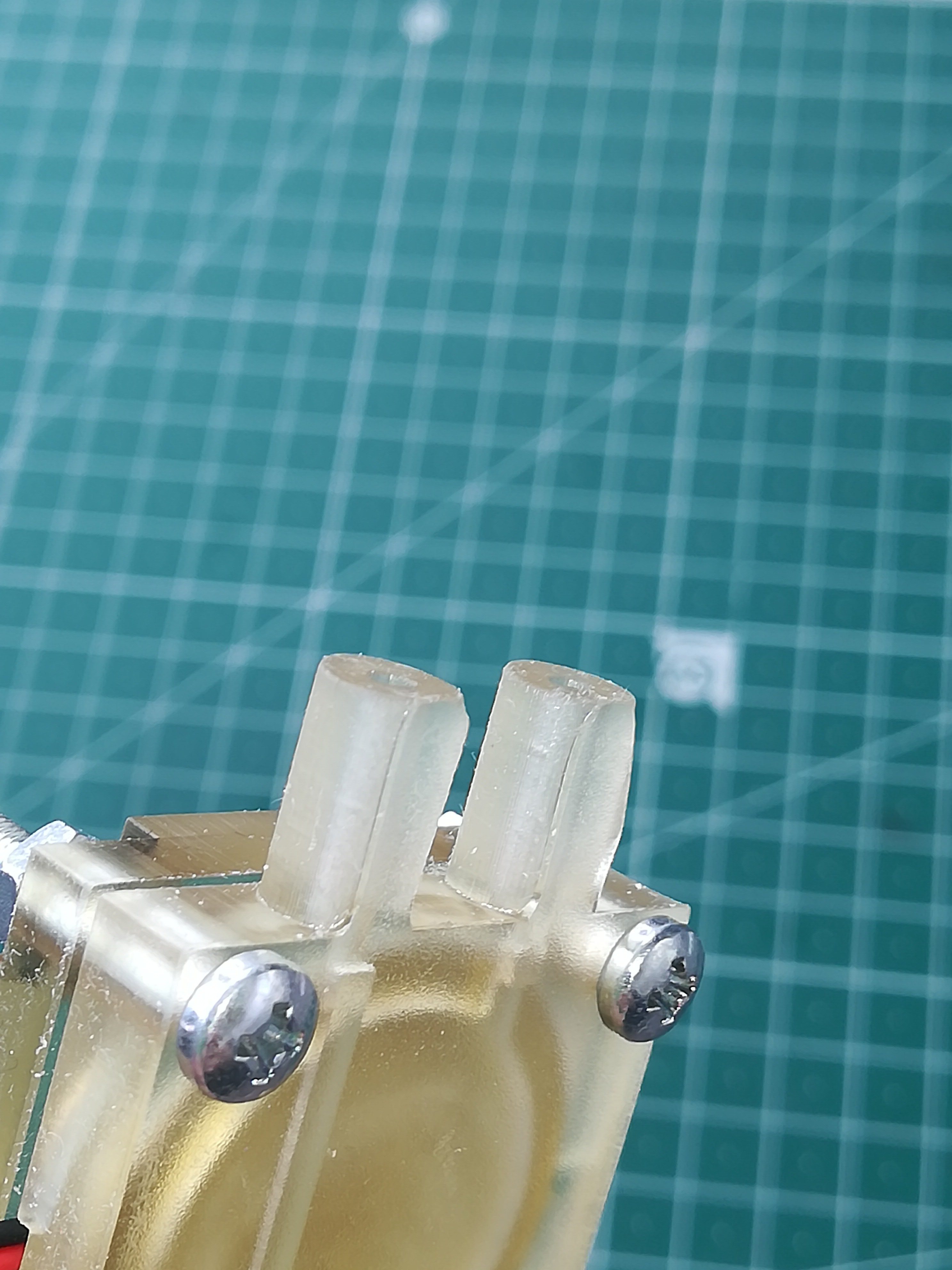
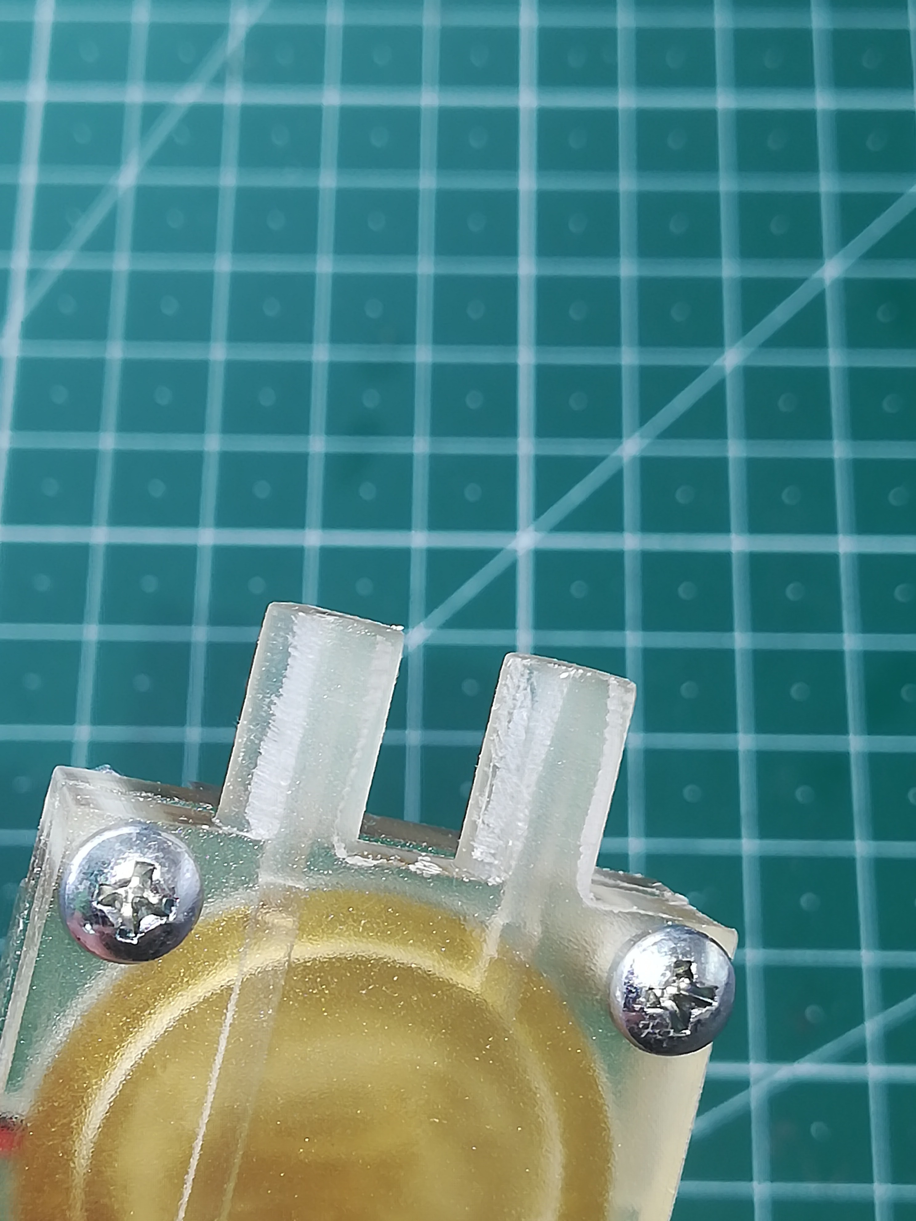
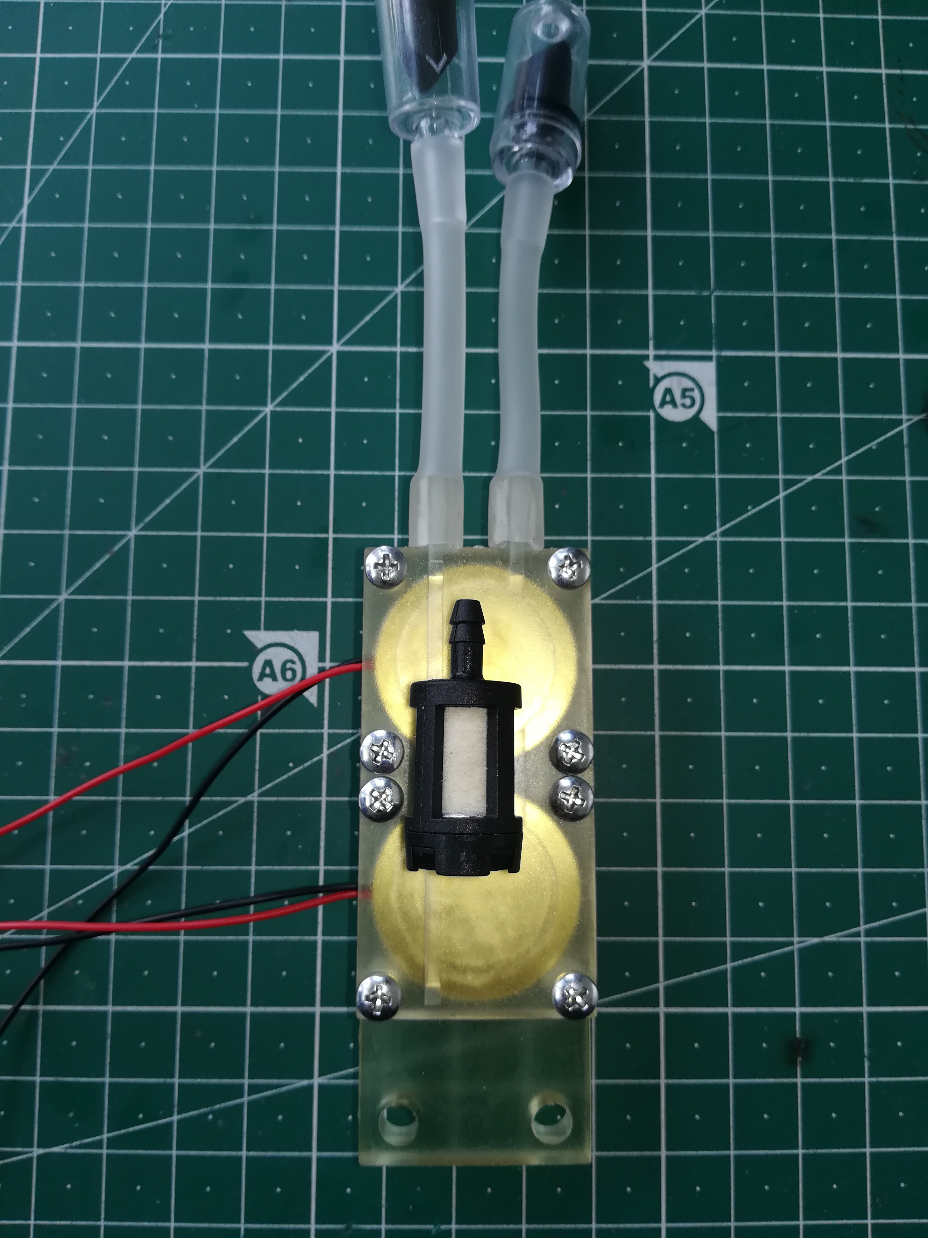
Next you need to put the tubes and check valves onto the connections. For that it could be necessary remove ridges at the connection by filing, to get a sealed connection.
After that you can add the check valves to the pump...
and connect the ink container and printhead to the pump.
For keeping the ink clean add the petrol filter to the tube in the ink container.
Mount the pump with two M5 screws and nuts to your machine and you have finished the assembly of the pump.
9
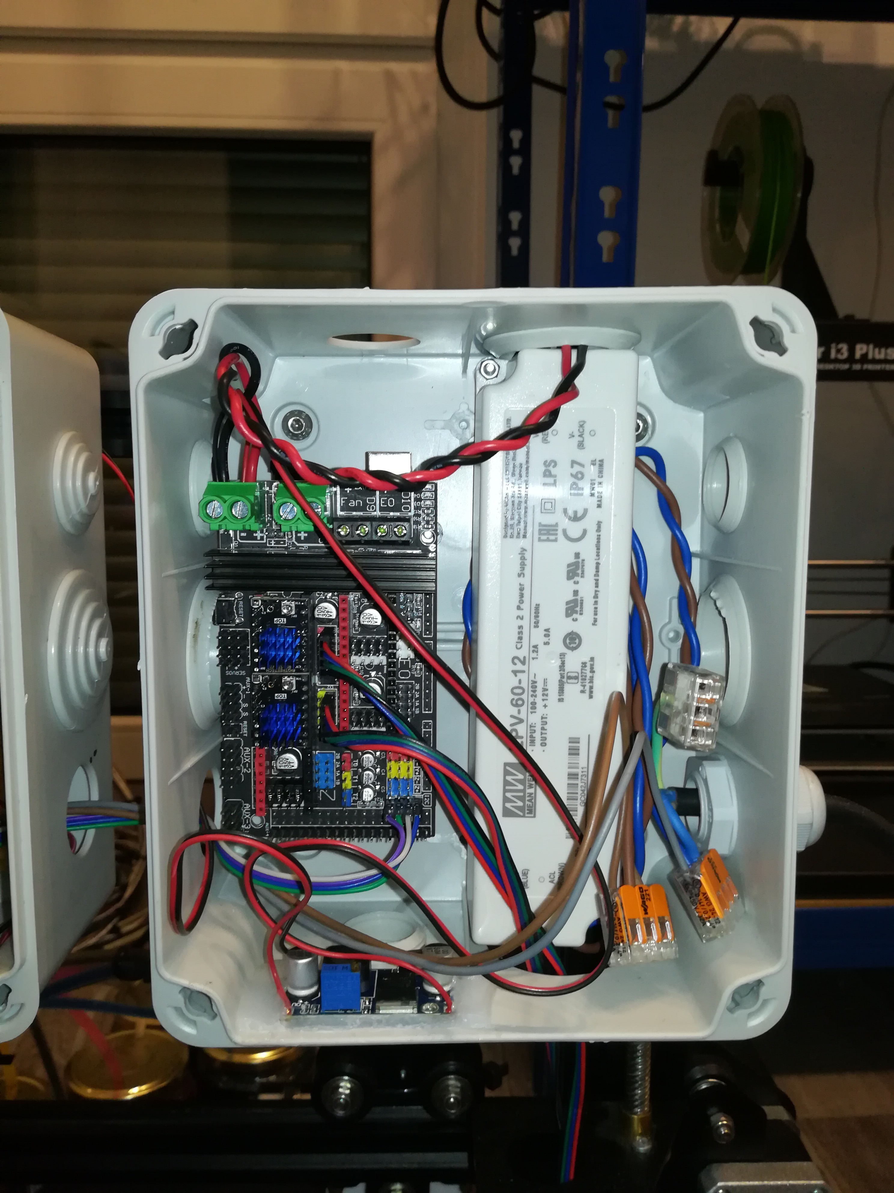
Machine Electronics
For controlling the machine I used an Arduino Mega 2560 + RAMPS 1.6+ with two TMC 2130 stepper drivers which is powered by a 12V 5A power supply.
The RAMPS is connected to the two stepper motors and also to an Arduino Nano via i2c, GND and 5V connection.
There is also an LM2596 wired to the 12V power supply which is connected to the vacuum pump to reduce the voltage for less noise - so it is just optional.
The mains power is distributed to the 12V power supply and the other electronics box via WAGO 221-413 terminals.
10
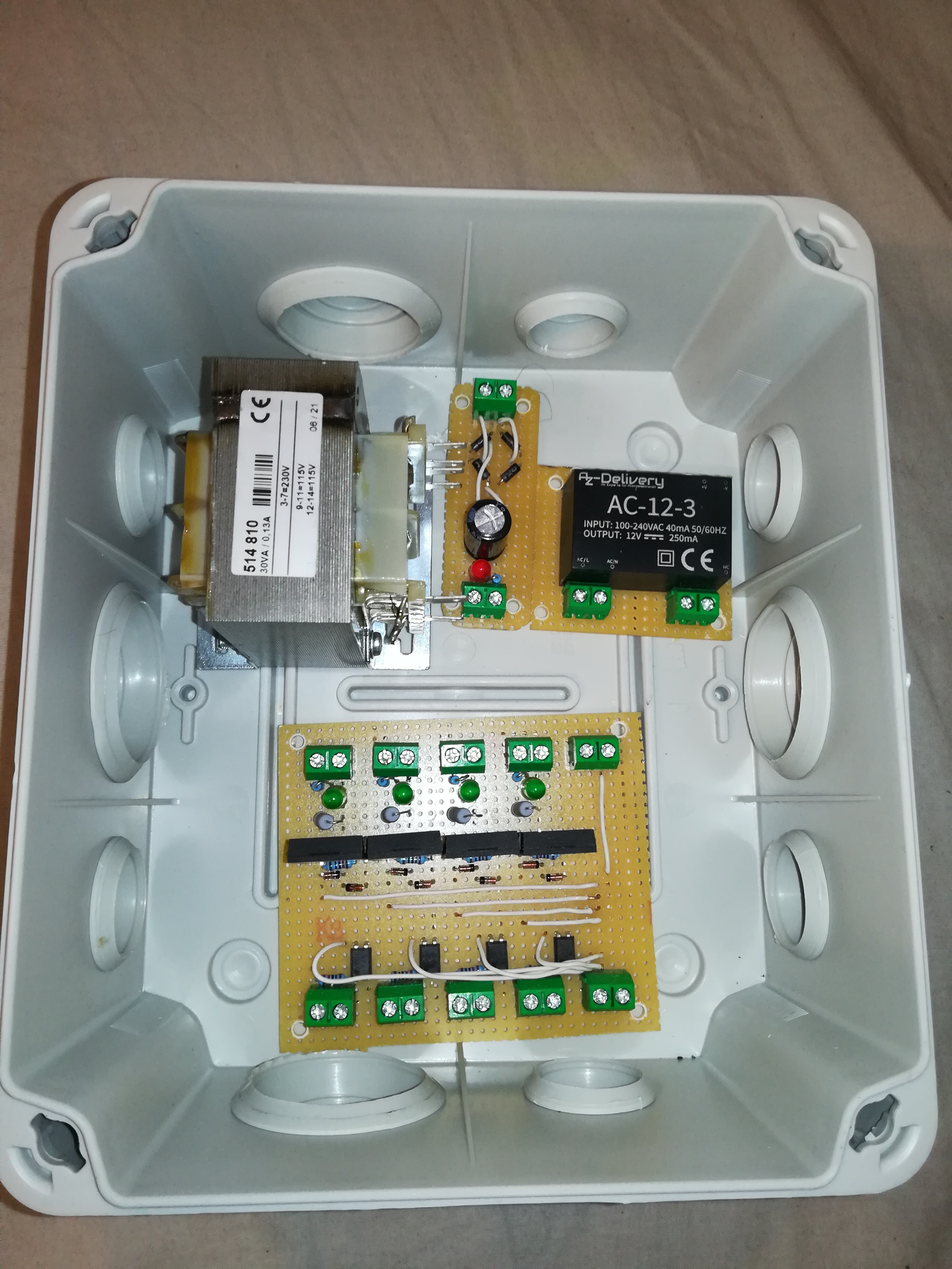
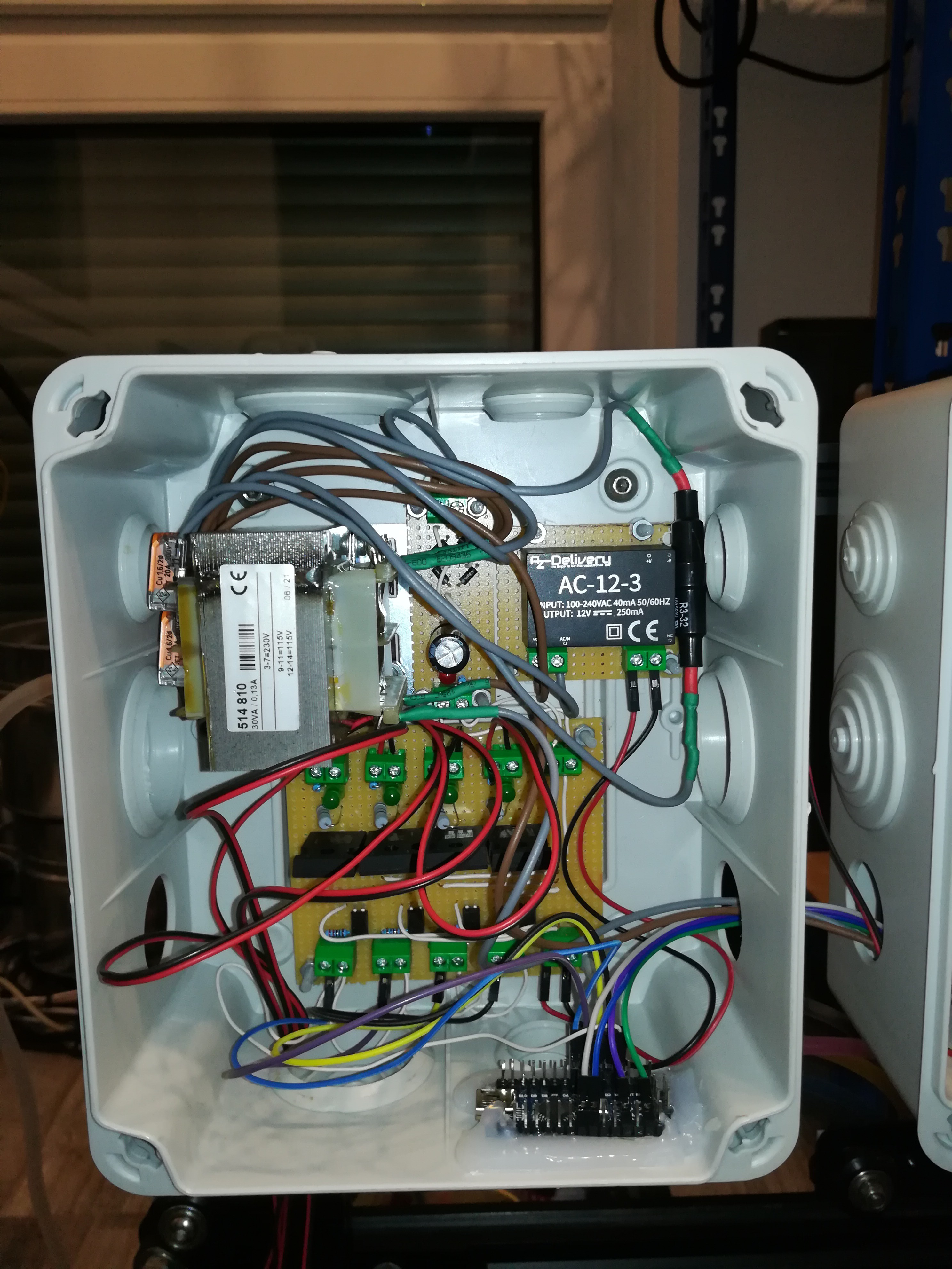
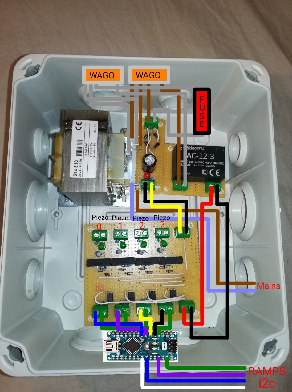
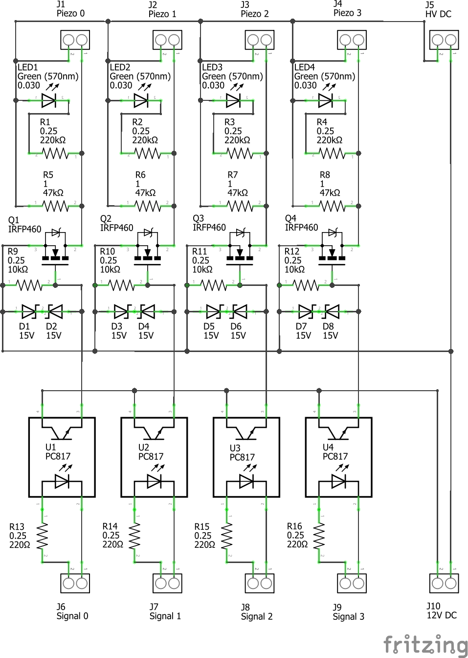
Piezo Pump Driver
The electronics of the piezo pump driver consist of the following parts:
A transformer for transforming 230VAC to 115VAC and isolating from mains.
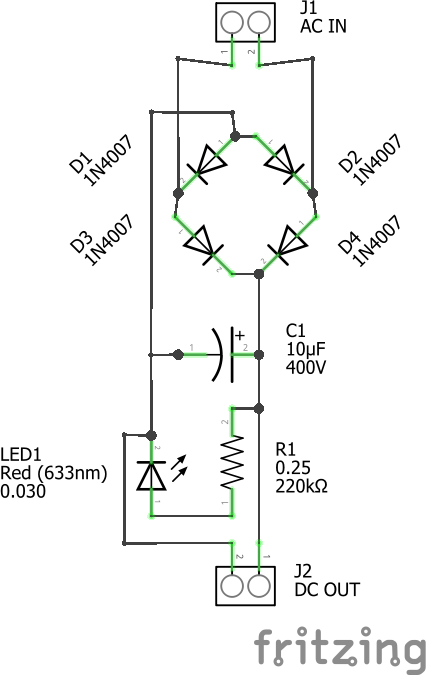
A rectifier for converting from AC to DC
A separate 12V power supply for driving the MOSFETS
An Arduino Nano to receive i2c data and switch the MOSFETS
A board with optocouplers, MOSFETS, and resistors for isolated switching and discharging the piezos.
 Dominik Meffert


Discussions
Become a Hackaday.io Member
Create an account to leave a comment. Already have an account? Log In.