-
1Order and Print Components
The first thing you’ll want to do is order and print all of the necessary components. The printed components are all available on Github here. After the initial design, I ultimately had to add a hole for the temp sensor on the fan enclosure and I didn’t modify the design to include this. I also found that the slots I made for mounting the fan enclosure to the fan with zip-ties weren’t big enough for some of my zip-ties, so you might want to check this measurement for yours
-
2Solder up the boards
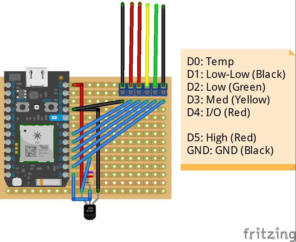
For the fan controller, I used a small PCB proto board and for the temp sensor I simply soldered the sensor directly to the Xenon. It’s all quite simple, but follow the schematic below for the fan controller and you shouldn’t have any issues
![]()
-
3Assemble both devices
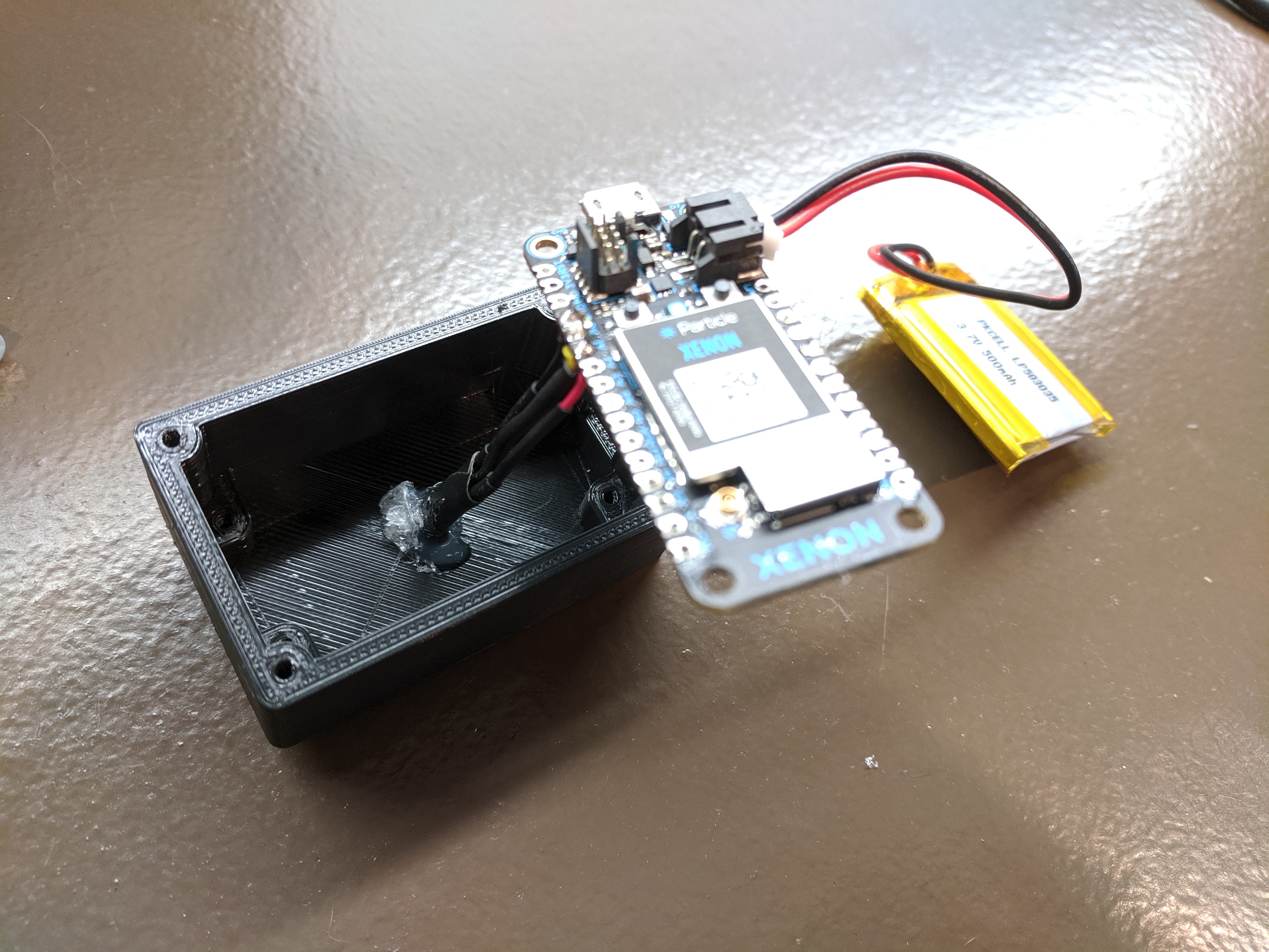
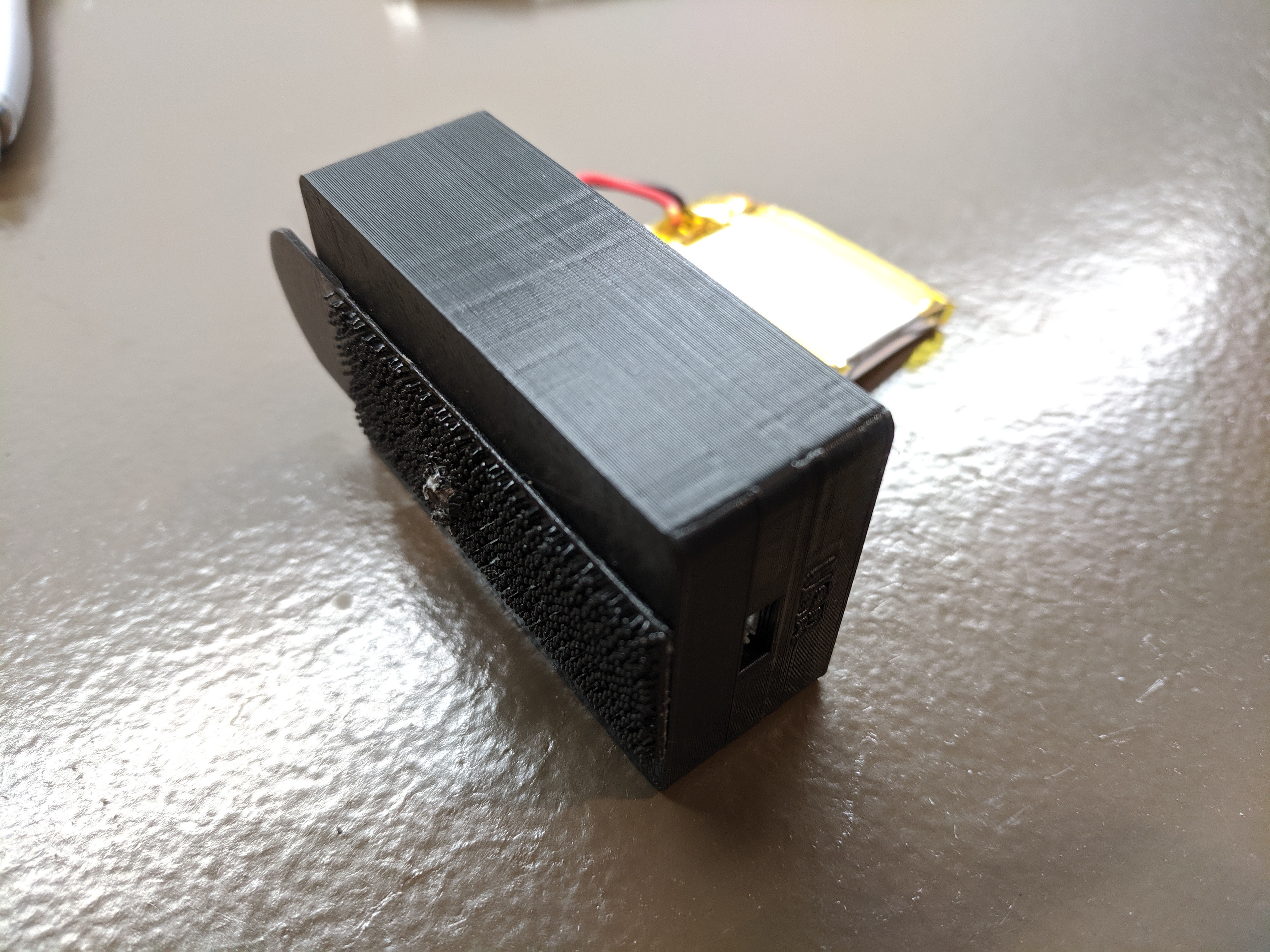
With the finished boards and the printed enclosures, assemble everything. I originally had intended to wrap the temp sensor on the back-side of the temp sensor enclosure. Unfortunately, I broke the leads doing this and ended up wedging a replacement one in the hole and securing it with hot glue. I then used a drill bit and by hand made small holes in both of the 3M Command strips I used to attach it to the back of the fireplace.
![]()
![]()
![]()
-
4Make the connections
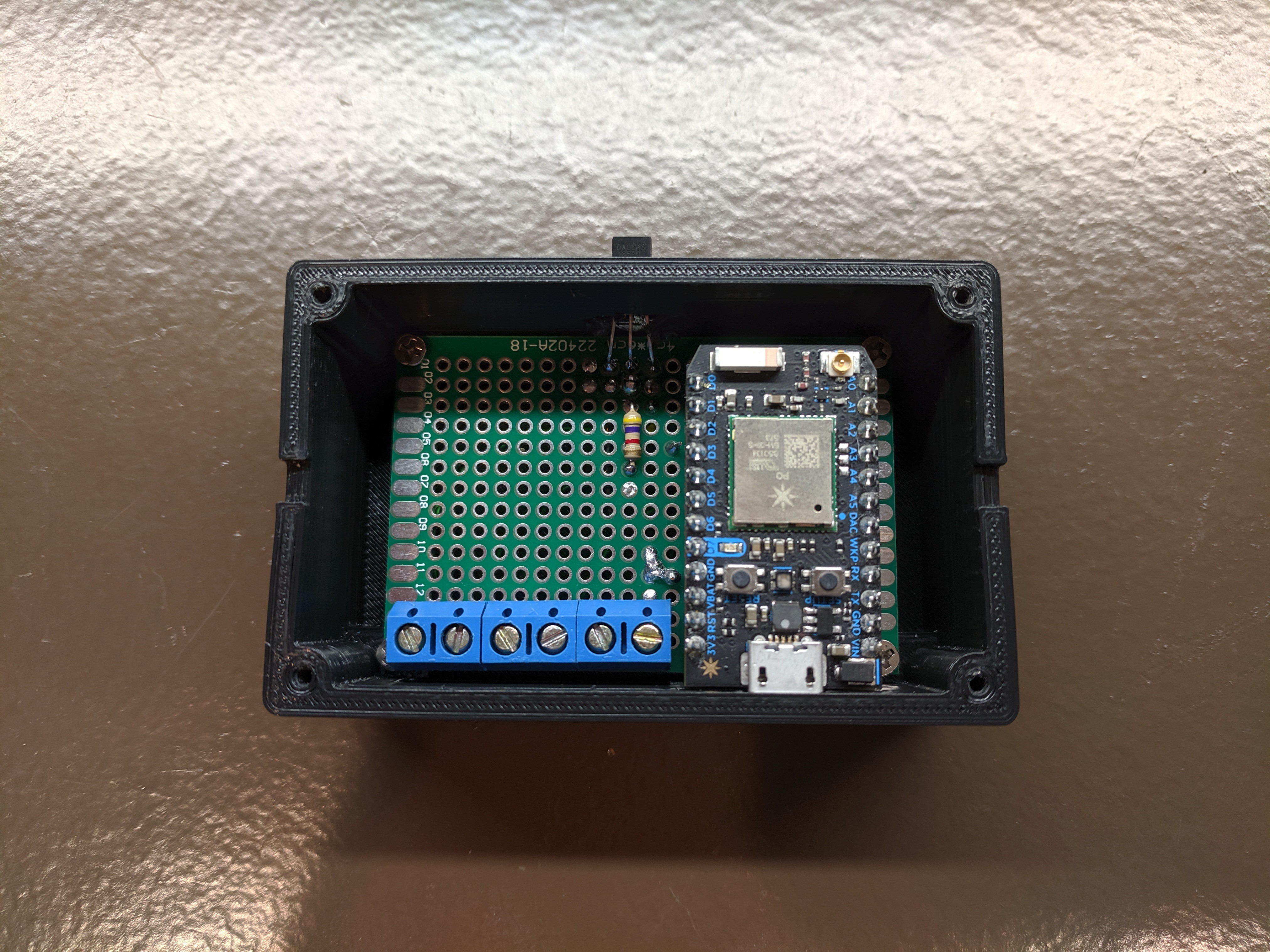
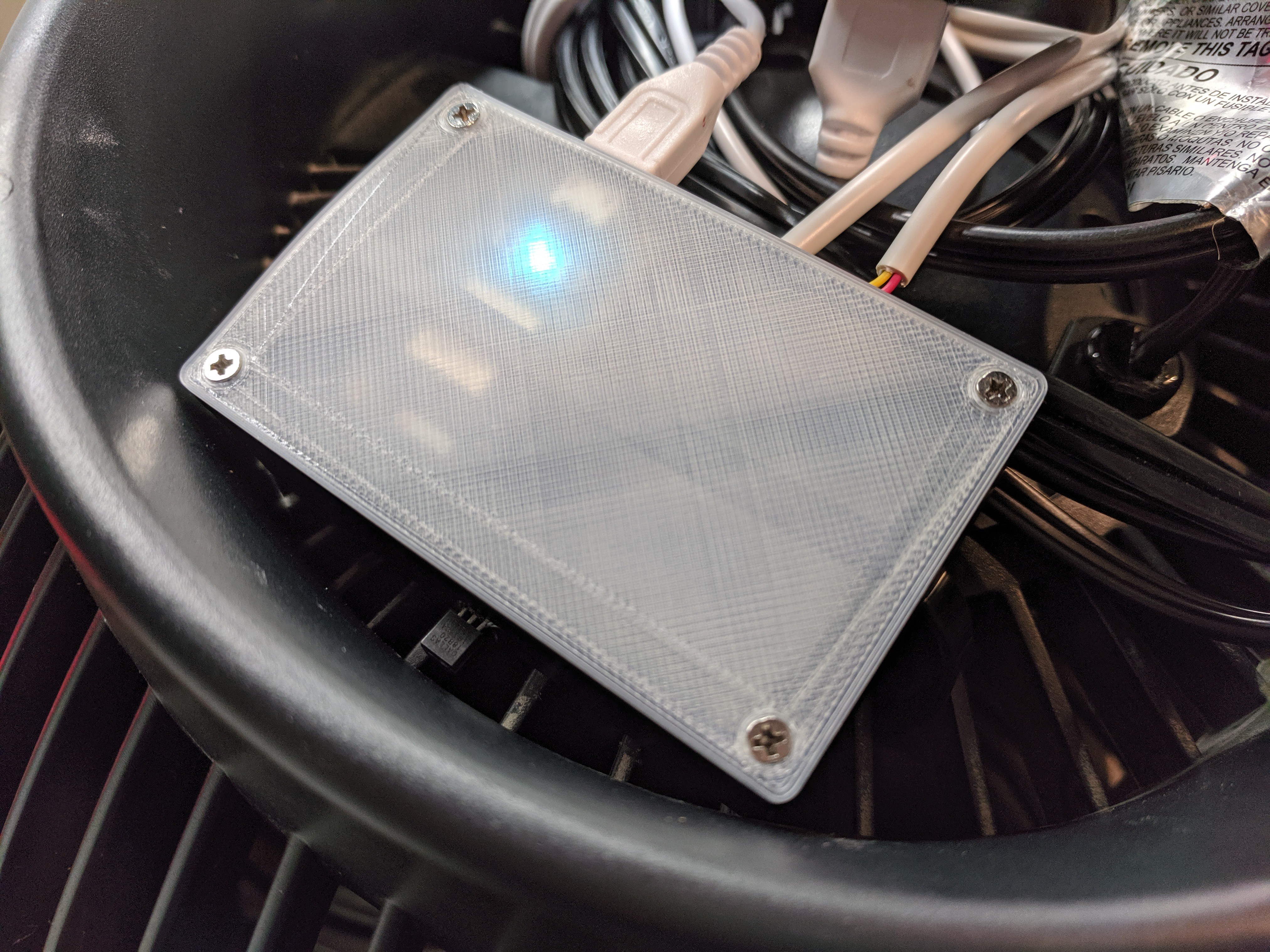
I’m going to assume that you’ve already made connections to your specific fan. All that’s left is to mount the fan controller enclosure to the fan and connect the wires you’ve now got for the fan.
![]()
-
5Power it all up and edit the code as needed
The code is located on Github here. It’s written for a Particle Photon for the fan controller and a Particle Xenon for the temperature sensor but should be easily edited to work on a similar Arduino.
-
6Set the mode
The fan controller starts up in ‘heating’ mode, but if it’s summer-time you’ll need to publish a ‘Fan_Command’ with data of ‘Cooling’.
Automated Fireplace Blower
Simple project to save energy and learn to work with Particle Mesh devices.
 Ben Brooks
Discussions
Become a Hackaday.io Member
Create an account to leave a comment. Already have an account? Log In.