Thomas
-
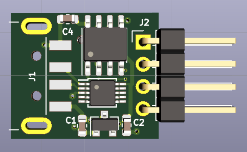
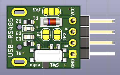
Making a USB-RS485 dongle that cuts the right edges
11/05/2019 at 20:39 • 0 commentsAs pointed out before, cheap Chinese "Green-Black USB-RS485 dongles" are cheats: what's the point in using an RS485 driver when driving just "ones" and replacing "zeros" with a bias circuit?
I decided to make another small board and order from @oshpark's excellent prototyping service.
![]()
![]()
This RS485 adapter even has an "echo" switch, which makes using RS485 for the STM8 eForth two-wire interface possible.
Using it as a simple RS232-TTL adapter for 3-wire or 2-wire configuration is also a configuration option. More details are in theRS485-CH340E repo on GitHub.
-
Building STM8 eForth for MODBUS boards
10/26/2019 at 06:51 • 0 commentsSTM8 eForth supports a range of boards. and provides a method for building new ones. The problem is that the new board needs to be added to the STM8 eForth repository or a fork of it.
This has changed with the pre-release STM8 eForth 2.2.24.pre1: the source code is part of the release archive, and maintaining a board configuration in a "downstream" project is possible:
The STM8 eForth MODBUS repository now has a first "board folder", and building a Forth binary for the STM8S001J3RS485 board is as simple as cloning the repository and running the following:
make -f forth.mk BOARD=STM8S001J3RS485 flashOf course, you also need to install STM8FLASH and the SDCC tool chain (or use a docker-sdcc).
Work on variant build in downstream projects, and auto-build of STM8 eForth isn't complete (providing binaries with MODBUS code needs some chainges), but the main building blocks are in place. -
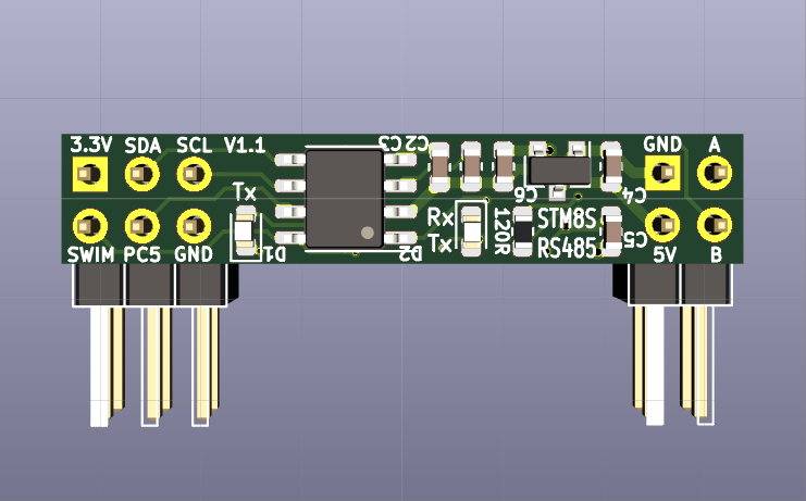
STM8S001J3RS485 MODBUS Sensor Board V1.1
10/13/2019 at 19:51 • 0 commentsWhen doing hand soldering I learned "first hand" that the orientation of 0603 components matters, and consequently I worked a bit on the component placement of the tiny STM8S001J3RS485 PCB. Using 8 mil signal track width, 6 mil clearance and 10 mil via drills made it a lot easier compared to sticking with the KiCad defaults. The power supply now forms a rail from left to right, switching the side of the PCB about in he middle.
The text on the silcscreen is friendlier, too (even if they make good use of the 400DPI silcscreen that @oshpark provides (i.e. the print is tiny):
![]()
The 0603 components on the back side now are also easier to populate.
![]()
The new board is available on the @oshpark shared project pages, and the GitHub repo has been updated.
-
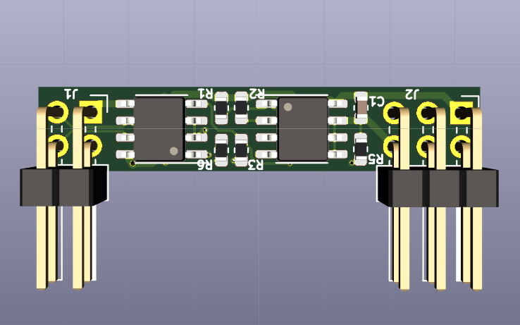
STM8S001J3M3 RS485 Mini-MODBUS PCB Rework
10/11/2019 at 21:01 • 0 commentsI found the first version of Mini-MODBUS PCB a bit difficult to populate by hand (using a fine tip shouldn't be necessary). The component placement around the power supply was all but ugly, and pin description and other information were missing on the silkscreen.
The reworked design is a lot nicer (and also easier to assemble). Making better use of the limits of @oshpark design rules (vias, drill diameter, clearance and track witdh) was helpful. Schematics and size remained unchanged.
-
First test of the STM8S001J3RS485 Mini-MODBUS "board"
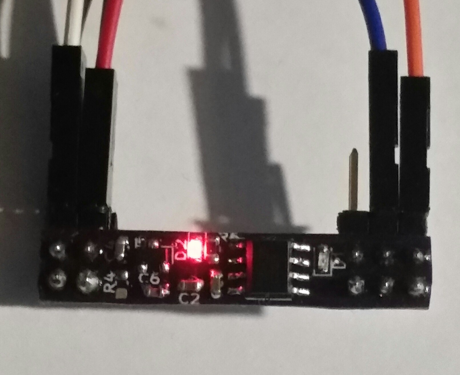
10/08/2019 at 20:22 • 0 commentsPopulating a 6x34mm PCB with 0603 components on both sides isn't easy and the result isn't pretty. For the next batch of 5 PCBs I'll try some sort of reflow process.
![]()
Bidirectional RS485 communication works (i.e. the Forth command line via RS485). I didn't populate and test the DS1621S chip - a little suspense can't do any harm ;-)
Cables from left to right: RS485 (B is white), power supply (+5V), simulated UART for primary console (PC5), SWIM (PD1). Using SWIM while PD5 is in "half-duplex UART Rx mode" works fine.
-
PCBs for Tiny MODBUS Nodes
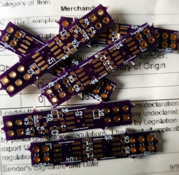
09/17/2019 at 17:58 • 0 commentsFree delivery from the USA is fast enough for people with a daytime job - the PCBs lingered for 5 days in the German customs, so in a world without trade barriers it would have taken just 12 days from uploading the KiCad files to delivery!
![]()
The PCBs look quite good. Fortunately the 4k7 0603 SMD resistors did also arrive today. I hope to get the first tiny MODBUS node working
by the end of the comming weekend. -
Finding the culprit
09/08/2019 at 12:41 • 2 commentsMy MODUS implementation on the STM8 eForth platform works. It was the RS485 communication that left me frustrated for a couple of months.
Since recently "designed" a small PCB to bring SO8 STM8S001J3M3 to good use, and now RS485 testing should better work.
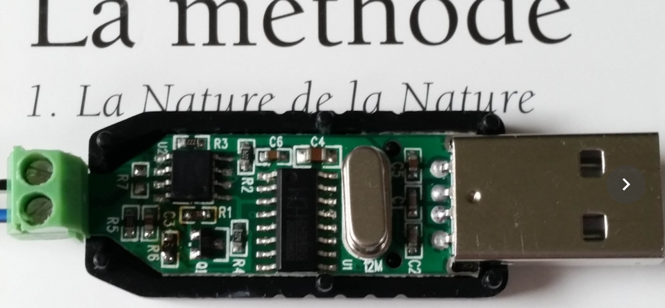
The problem is that the one USB to RS485 adapter that I own, a Green+Black $0.80 gadget, doesn't play nice with my Ubuntu PC. In fact, it's able to receive things but transmitting leads nowhere. Besides, it makes as well Picocom, e4thcom and my JAMOD test hang on exit.
The PCB of the board has YYH-256 stamped on the back. The circuit appears to be simple enough:
![]()
It's based on a CH340G, the venerable Chinese USB RS232 interface chip. Has a full set of hardware handshake signals that potentially could be used for switching between Rx and Tx mode. Potentially, because there is no documentation whatsoever.
I first started playing with Picocom DTR toggling but stopped doing that (and felt a bit silly) when I remembered the Linux kernel USB-serial non-features.
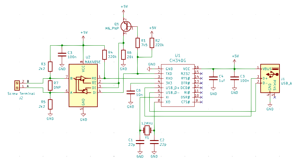
Next I started to think how cool it would be to have a circuit diagram of that simple thing. I fired up KiCad, and with the help of my trusty multimeter, I came up with this:
![]()
There is no DTR, no RTS, and thus no elaborate RS232 hardware handshake. Instead I find a *really optimistic* Tx based direction control. I would at least have expected a capacitor to prevent direction switching during transmission of a single character (!). No wonder that RS485-A is biased GND and RS485-B to 5V: the RS485 driver is only driving one polarity! The other one is just the 2.2k resistors doing their work (good luck with the promised 1 km) Is this how the CAN bus was invented?
I don't mean to say that such a circuit won't work under certain circumstances, but mine never did.
The next attempt was checking TxD for signs of life (pin2 of the CH340G), but again nothing.
A quick comparison of the circuit with a CH340G based standard USB-to-TTL adapter didn't reveal any difference: the inputs, besides RxD are N.C. as well (besides, I figured out why the same USB-to-TTL board never worked with the STM8 eForth two-wire-interface - some docs will have to be changed).
There can be just one conclusion: the CH340G on the RS485 Black+Green adapter must be broken.
EDIT: Today a new "RS485 Green and Black" dongle for $0.82 (including postage!) arrived. It worked as expected, but of course because of the design it's only usable for testing or configuring a device on the bench.
MODBUS Things with STM8 eForth
Projects (and mishaps) for talking MODBUS to STM8 eForth