 Andrew
Wiring:
- QMC5883L: 3v or 5v, GND, D1 (SCL), D2 (SDA)
- Reed Switch: GND, D7 Relay: D8 (you can modify the pin # on V2, or physically cut D1 pin and add bodge wire)
- Voltage Divider: GND (if not shared ground), A0
Voltage divider and reed switch terminal are soldered to a shared proto board
Initial Prototype:

As I’d suspected, when a vehicle or other large ferrous object (or even a hand placed closely) passed above the magnetometer, its readings would change significantly. Basic tests proved that I would be able to use this for my detection. After some hacking in ESPHome I eventually landed on creating a sensor with a 15 second moving average of heading readings, and triggering my relay if the current heading reading varied from the average for more than 3 seconds. Some additional logic was introduced to filter out sporadic bad readings and prevent gate from actuating too often (or closing on a car passing through!).
The below is what I came up with:
- Create sensor with average of last 15 heading headings (taken at 1s intervals)
- Create “automation safety” binary input to prevent rapid firing of gate open from readings
- If current reading varies ± 2.5° from average turn on internal binary sensor
- If binary sensor on for more than 3 seconds AND gate is closed AND our “automation safety” binary sensor is off: trigger the relay and turn automation safety on for 120s
In the above we have ensured that:
- Something (presumably a large metal object) has caused a change in heading and has stayed for some time
- The gate is closed and probably needs opening
- We won’t accidentally close the gate on a car passing through since our automation will only fire if the gate is closed.
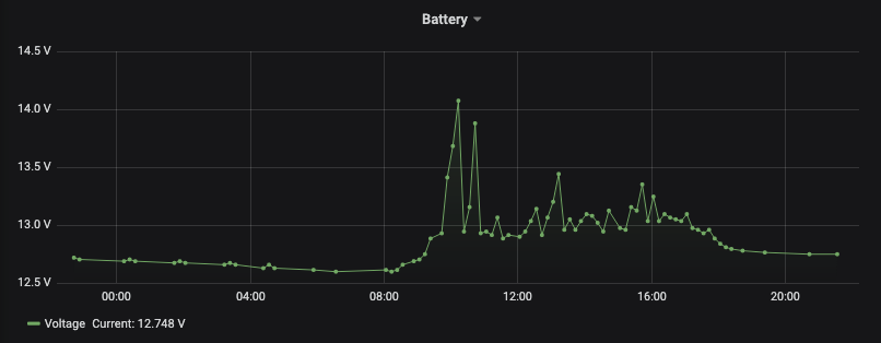
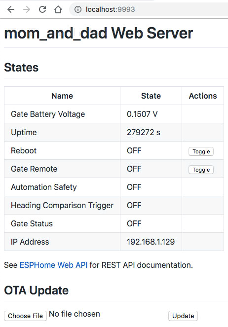
In addition to vehicle detection there is a gate status sensor (open/closed), battery sensor (gate and microcontroller run on 12V battery), and functionality to open/close gate via app/MQTT. I wanted to be sure this could operate independently (I run Home Assistant at home but they live far away) and have built it so that no external connectivity is required but if present will add additional functionality.
The vehicle detection was worked out in code and functioning as expected and then I dove into the gate and battery status sensors. The gate status was easy, just a simple reed switch. The battery sensor required an additional voltage divider. The D1 Mini has a voltage divider already but cannot accept the voltage of the gate's battery (12V deep cycle). I added an additional voltage divider and wired it to A0. With the additional divider I expect to see a voltage ~15.43 times less than the real voltage.
Prototype 2:

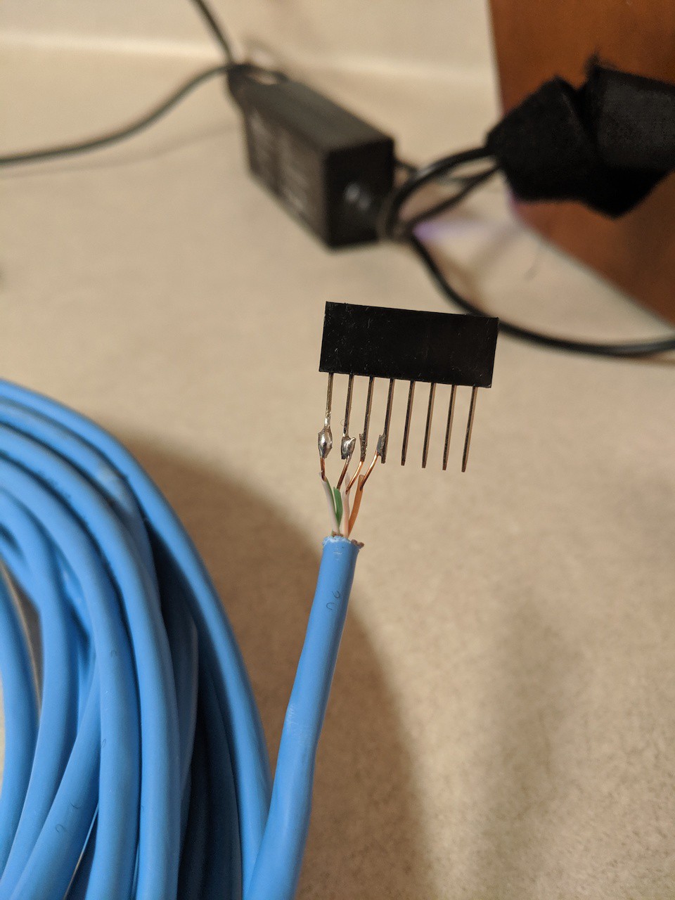
QMC5883L was connected to proto board via 2 pairs inside CAT5:
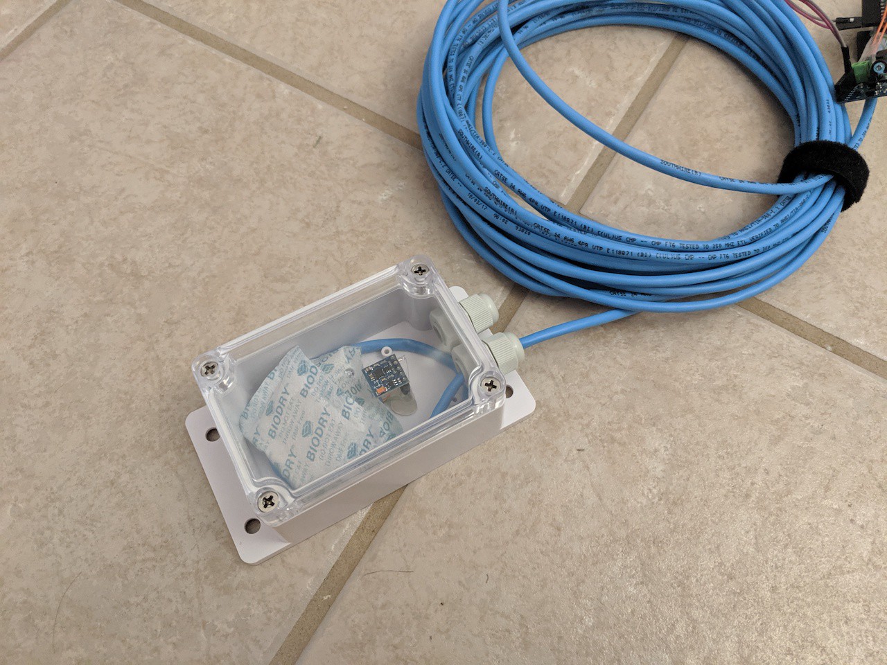
Magnetometer mounted inside Sonoff IP66 junction box. This was buried underground inside 4" PVC for protection under rock driveway. (moisture absorbing packets optional, hopefully not needed!)
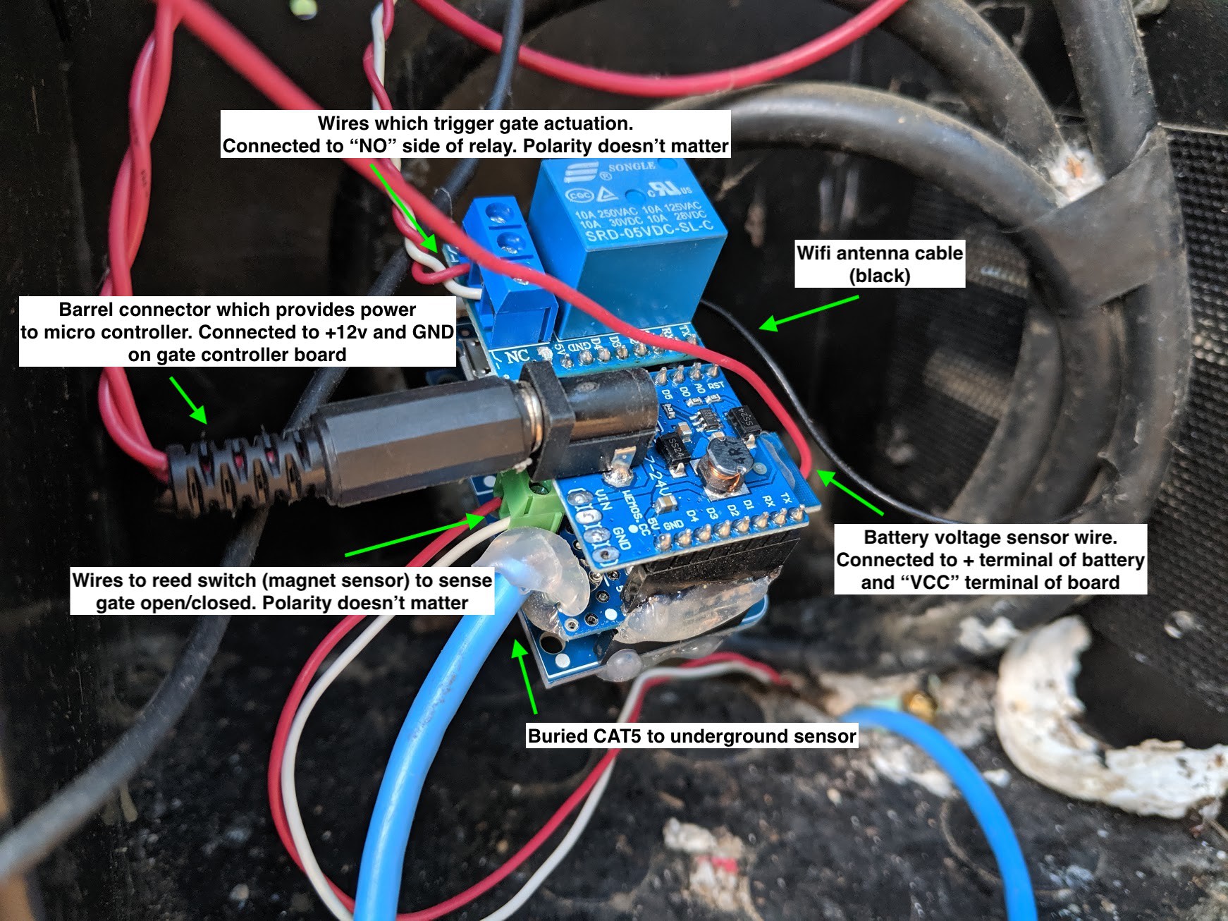
Completed Front:
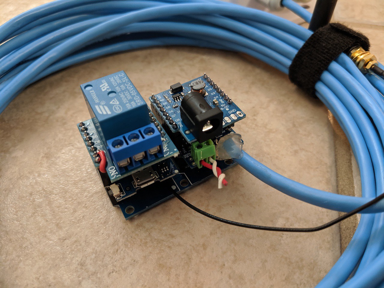
Completed Back:
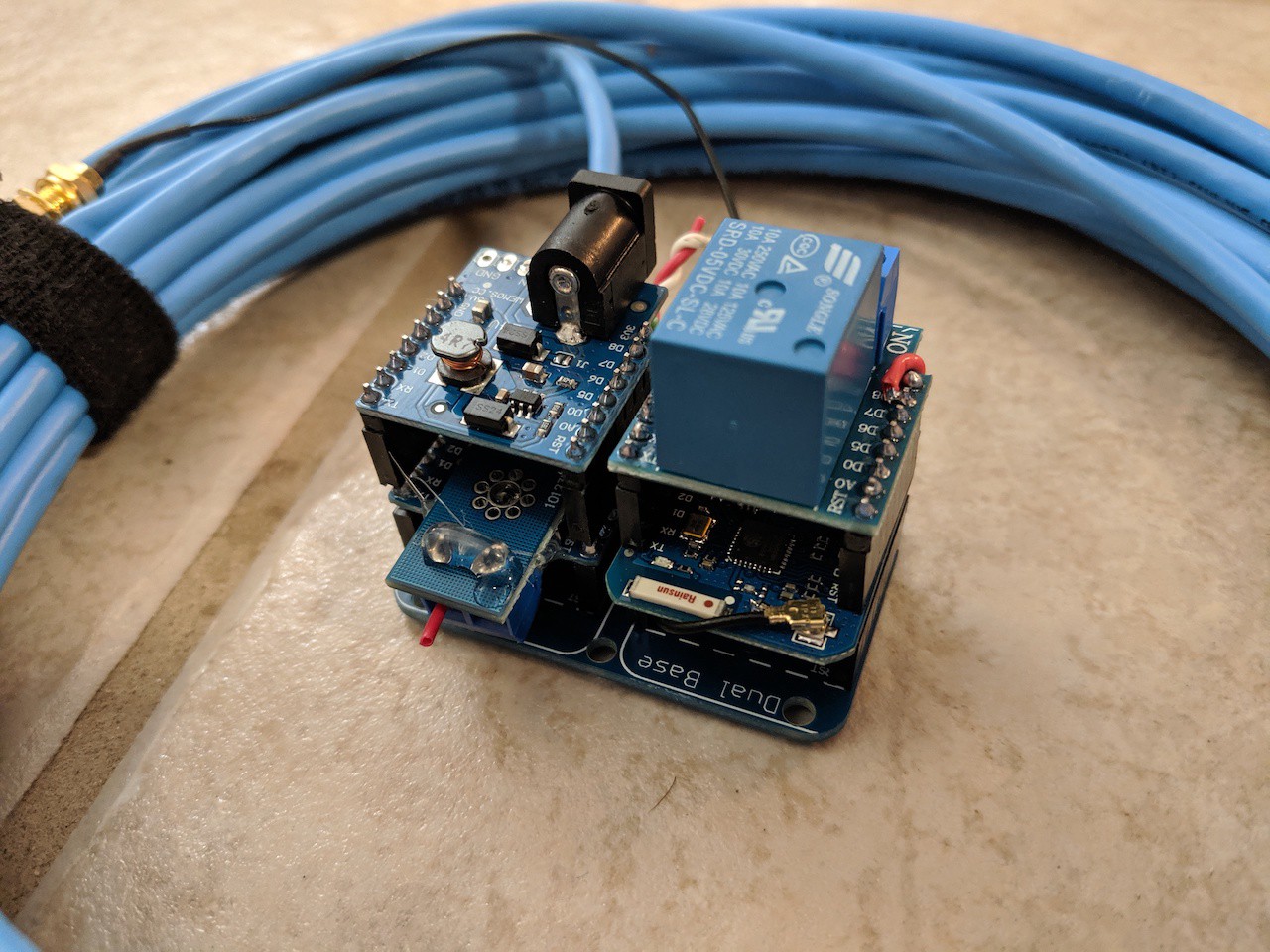
Installed in gate controller housing:
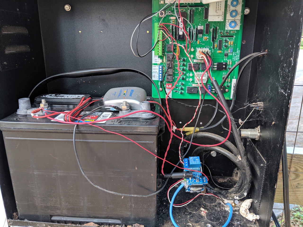
Wiring:
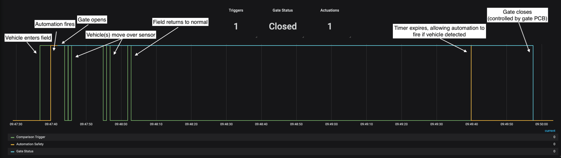
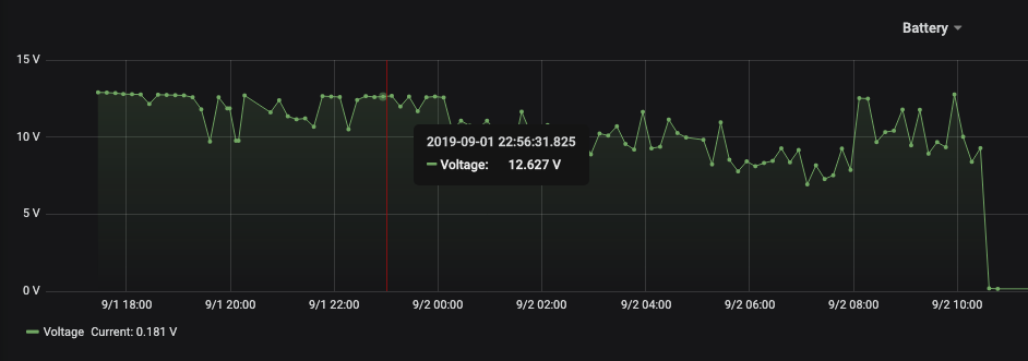
While the device is self contained and doesn't require a network connection, if it does have a connection it will send data over MQTT. The above image is from Grafana. In it we can see the full flow of a vehicle entering the detection zone, the heading deviating from average, automation firing, gate opening, vehicles passing over sensor, timer expiring, and gate closing. This works exactly as intended!

How long is the cable you use for the cat5 to interface the d1 with the compass sensor? I can't seem to get mine to work for more than a few feet which I get is a limitation of i2c but I'm hoping there is something to do to extend that as I don't get wifi down where I need the sensor.