-
Getting to neo-blinky
10/03/2019 at 06:44 • 0 commentsThe next step is hooking up some WS2812B LEDs (neo-pixels).
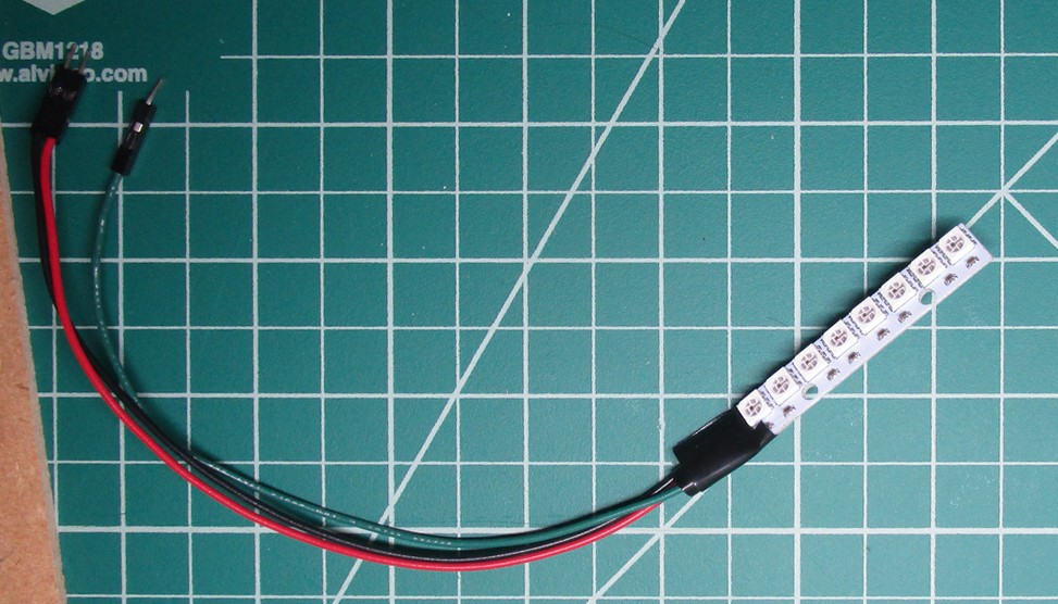
Normally that's a matter of getting one of these prefab strips, plugging it in and doing a quick copy & paste job from some example code
However, my final circuit is a custom PCB, so I need to figure out how to hook things up without using a prefab strip.
First step is to grab some WS2812B chips, solder on some leads, and then put a nice blob of hot glue over the solder joints so that the wires don't rip out halfway through setting up the circuit board.
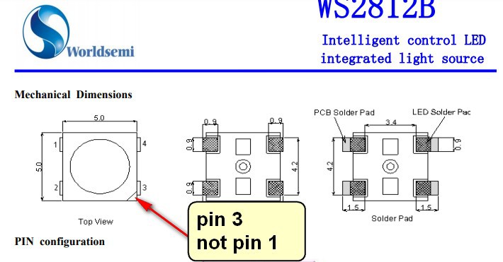
Second step is to take a second look at the data sheet and notice that the corner with the little triangle mark is pin 3 (not pin 1). Fortunately, these chips don't seem to be particularly fragile.
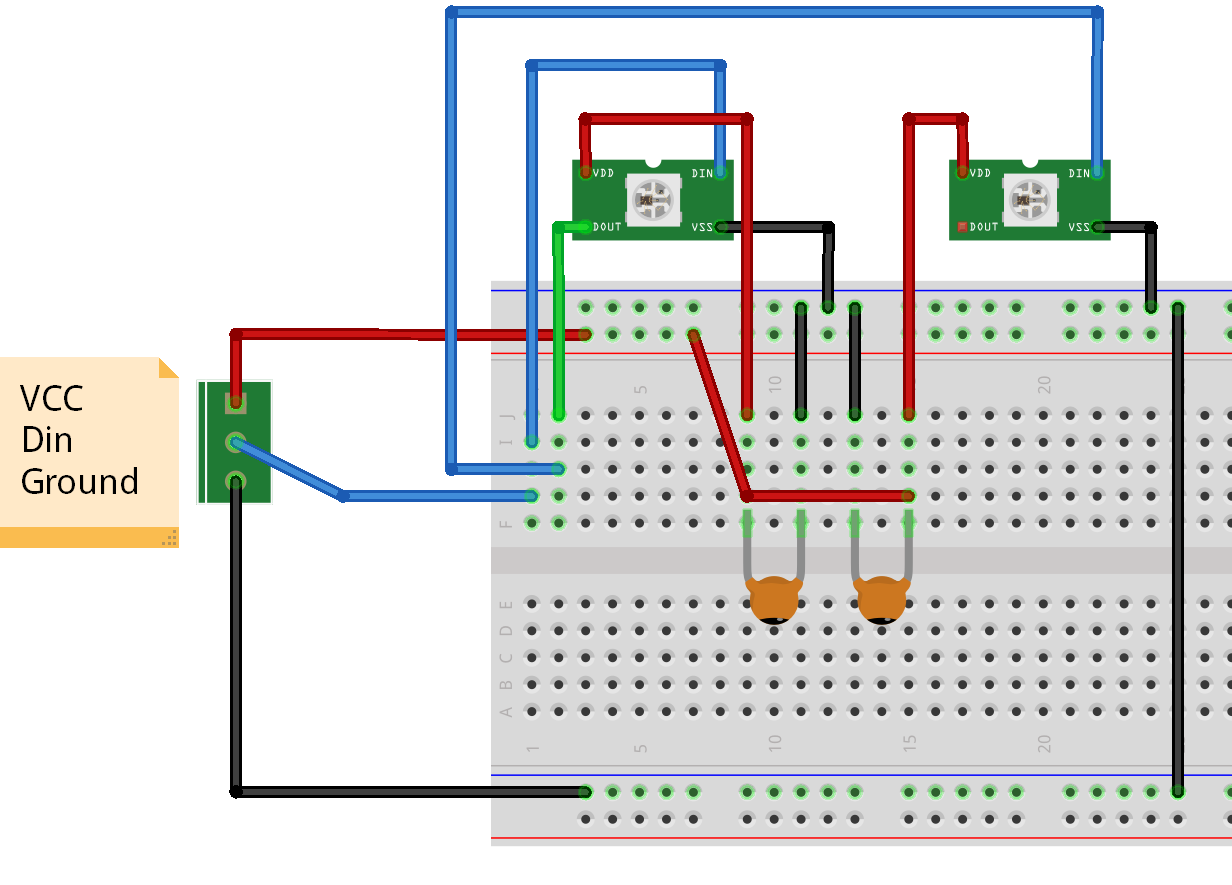
Wiring these up looks a little like this
![]()
I'm unclear as to the details of exactly why capacitors get placed in specific locations on circuit boards, so I'm trying to duplicate behavior from known working boards rather than trying to come up with the best wiring setup.
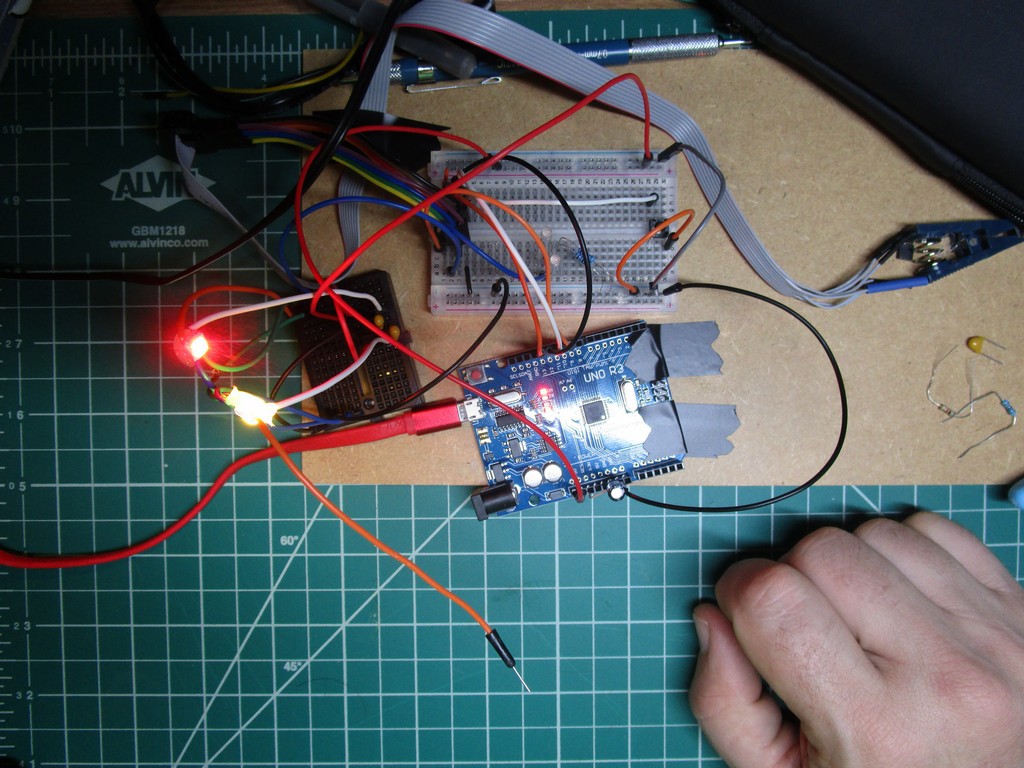
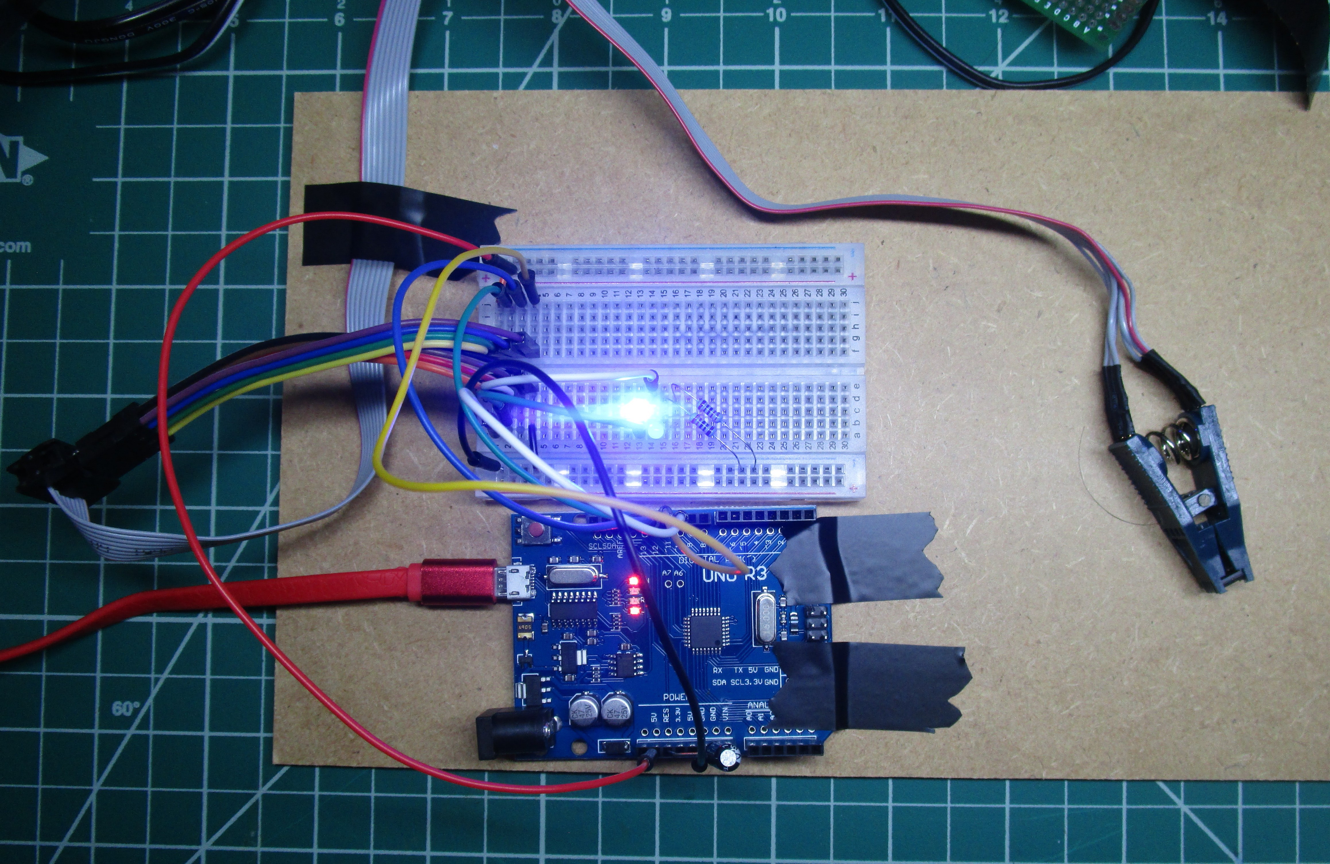
And after re-checking my wiring I have some color changing LEDs. Hooray!
-
Another lesson
10/02/2019 at 04:16 • 0 commentsIt seems I was using the clamp upside down.
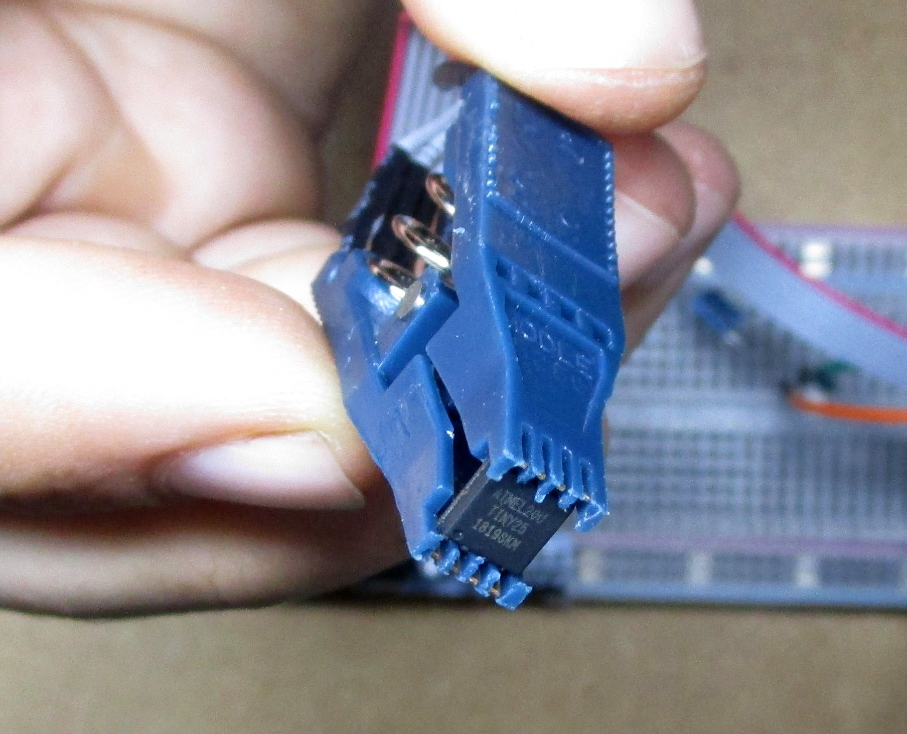
If you put the chip in with the pins facing up then the clamp does a much better job holding the chip.
![]()
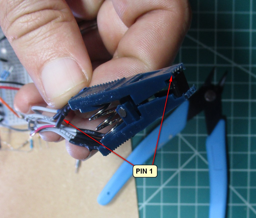
Then the red wire lines up with pin 1 on the chip.
-
Today I learned
09/22/2019 at 06:32 • 0 commentsWhen using the clamp on programmer the chip can twist so that the pin contacts are intermittent. If avrdude suddenly starts reporting bizarre device signatures (or just 0x00000000 or 0xffffffff) check to make sure the chip is parallel with the clamp jaws.
-
Getting to Blinky
09/11/2019 at 06:26 • 0 commentsThe first step is getting the ATtiny25 to be a blinky.
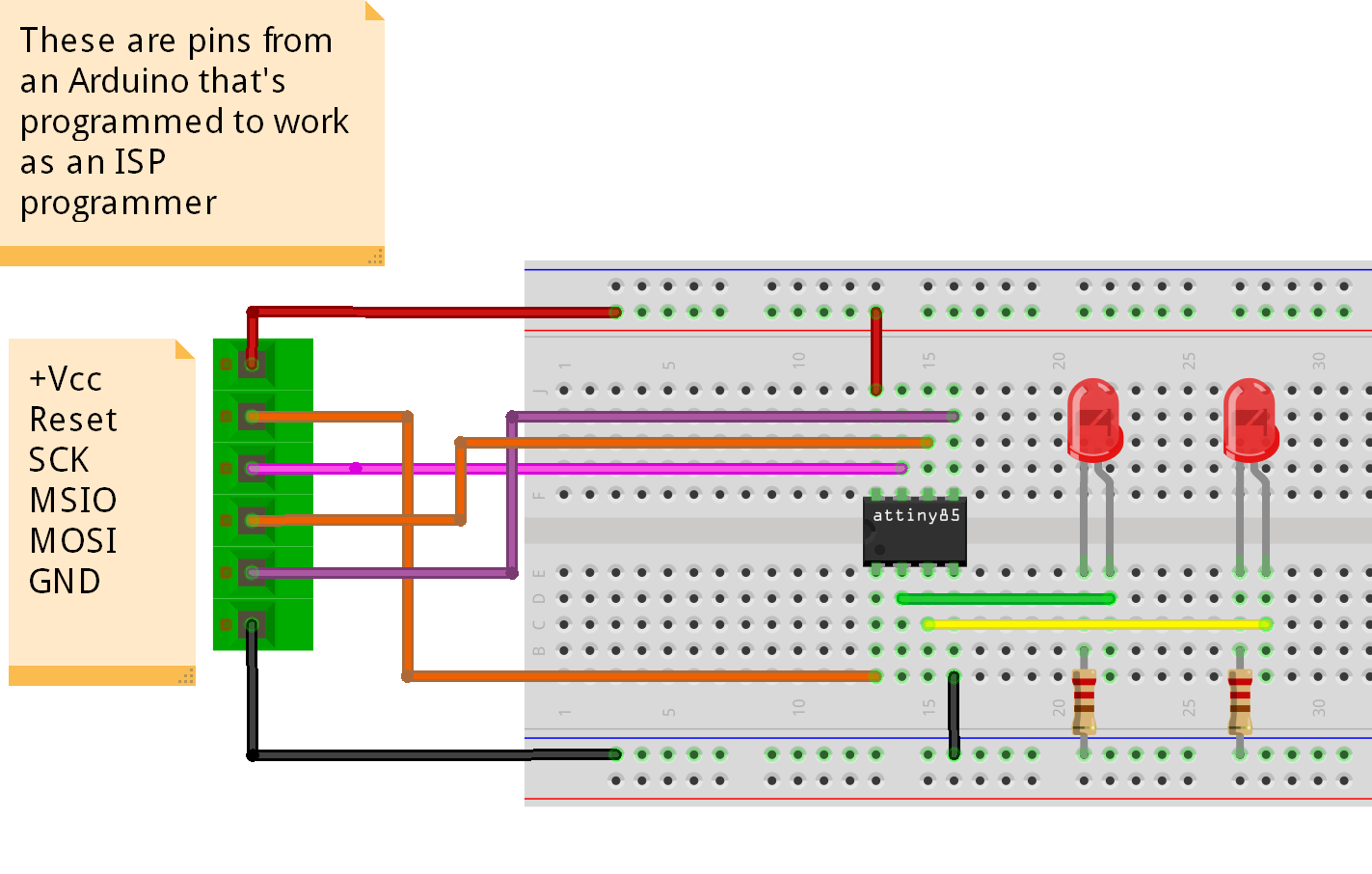
In theory that looks something like this:
![]()
However, rather than the DIP8 format I have a surface mountable ATTINY25-20SU, so it's going to go in this clamping gizmo that I bought off ebay.
When the clamp tightened down it felt like the pins bent. Hopefully the chip will still be usable later.
Burning the bootloader worked perfectly and the chip should be running at 8Mhz. Modifying the Blink sample to toggle pins PB3 and PB4 seems to be working.
 Matthew Reeves