Design
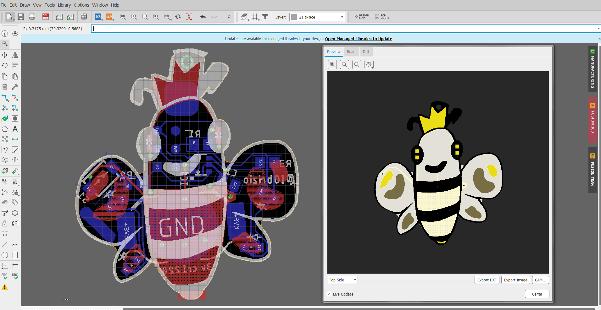
I started drawing the character on paper then imported to inkscape.
Autodesk Fusion 360 was helpful to get the PCB outline.

Electronics
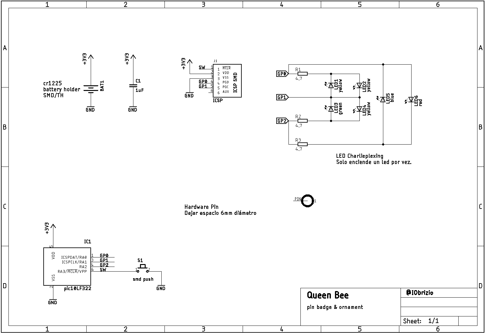
The circuit was captured on Autodesk EAGLE, this is based on low power & low pin count mcu, a pic10LF322.
This mcu has 4 GPIOS , 1 of them is just input.
•Operation Voltage 1.8V – 3.6V
•Up to 512 Words of Flash Program Memory
• 64 Bytes Data Memory
The electronics is powered by a cr1220/25 battery so this has to be power saving.
Manufacturing
I send to manufacture 2 versions of this board , one with HASL finish and the other one with ENIG finish , both came out gorgeous .
When you prototype with Seeed Fusion, they can definitely provide Free DFA and Free functional tests for you! Check out their website to know about their manufacturing capabilities and service.
Function
The LEDs are controlled by charlieplexing technique ,so 1 LED is running at time,this POV feature save power and works great with low pin count mcu.
The Queen Bee badge stills sleep in low power mode until you wake her up pressing the push button.
Pressing the button will change the LEDs animation until go to sleep again.
Aesthetics
- Use this as a Pin or on Necklace
- The PCB has ENIG finish , this gives to our Queen a real Golden Crown.
- Black silkscreen on whithe soldermask
- Light weight, so the pcb thickness is 0.8mm
- Small size, 30 x 35mm
- PCB was used as a light diffuser
Assembling - The fun part :D
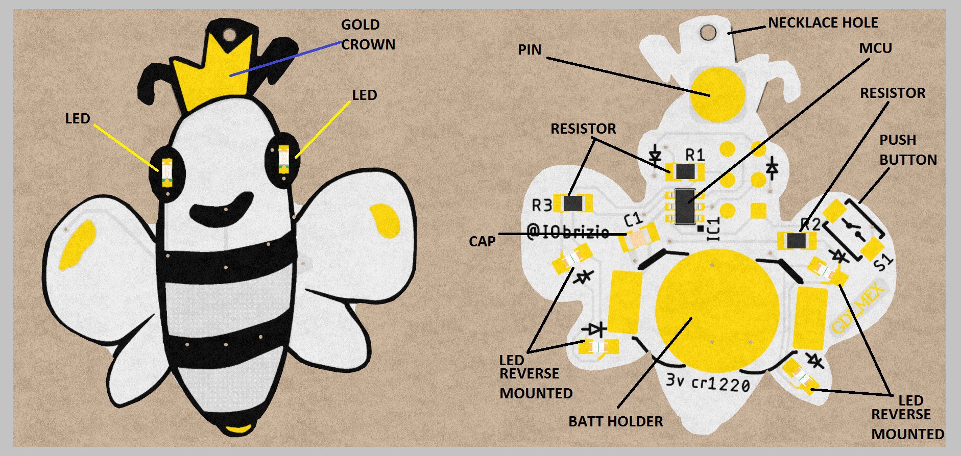
- On top there's just two LED s, I select yellow color for the eyes to not blind.
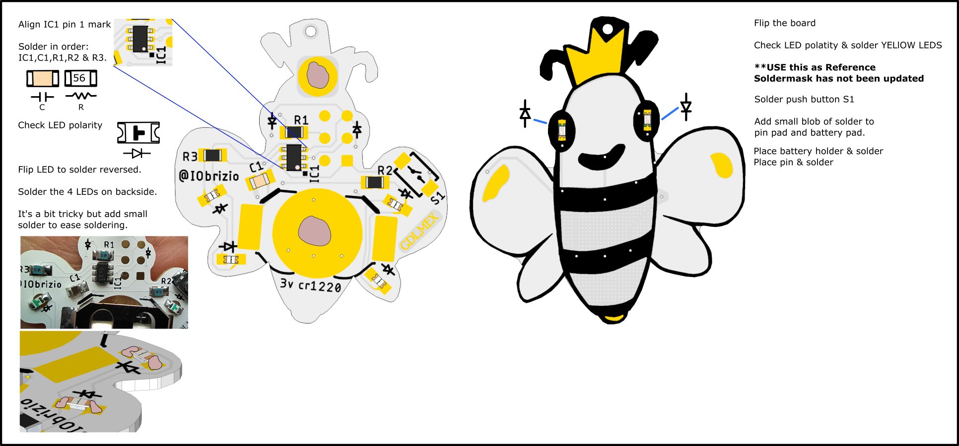
- On backside you can find 4 LEDs reverse mounted, this is to get a light effect ,looks cool.
- The components were distribuited to ease the soldering and optimize the space.
- I think the hardest part to solder is the mcu,it's a sot23-6 package,nothing special :P
A video or pictures hand assembling will be here
Tools required :
- Soldering iron / pliers / solder wire / flux
Where will it be sold?
- Selling them on Tindie -> (https://www.tindie.com/stores/gadgetfun/)
 Fabrizio
 potblitd
 davedarko
 Bob Baddeley