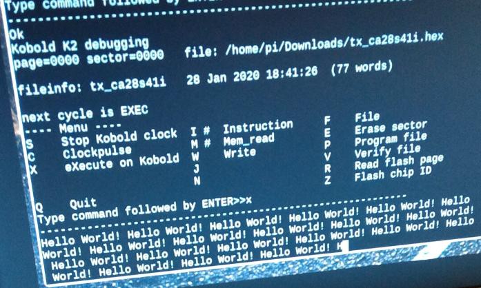
A milestone for every CPU project: print "Hello World !" !

SERIAL PROTOCOL
Having text output could have been a project all on it's own... but here I use the Raspberry Pi as terminal. On the main board of the Kobold, the connector to the RPi has two pins that are used here:
- signal SPI_CS3/ pin 11, RPi GPIO 11, clock signal coming from Kobold
- signal SPI_MOSI / RPI_DATA pin 2, RPi GPIO 13, bidirectional data
A simple synchronous protocol is used. The Kobold sends a clock signal, and on the data line it puts the character, complete with a startbit (low) and a few stopbits (high). It is intended that the RPi will be able to send data back over the same line, using the other edge of the clock signal. So the RPi can be the terminal for Rx and Tx, as long as there is no other way to do this.
The Python script at the RPi side got an extra section, started with the 'X' command, to receive the characters and put them on screen.
FILENAMES
A remark about the filename, you see on the screenshot that the TX program is named tx_ca28s41i. The reason is, that when you download the file from the webpage, you will get 3 files:
- TXT file with source code
- HEX file to put in the Flash
- LST file that shows the assembled source code
During debugging, you will download a lot of times. By always downloading the source at the same time, with the same timestamp (ca28s41i), you can always trace the source that belongs to an executable. And when replacing the binary file in the Python script, you only have to type the four last characters (thats the time-of-day) to replace the binary file with a newer one.
HELLO WORLD PROGRAM
And here is the program, dominated by the section for serial transmit:
; Kobold K2
; program name: TX
; character TX to RPi
; 20200128

start:
 nop
 movp 0,wp ; set wp page to zero
 movp 0x20,a2 ; A2 output address:
;
; A2+16 spi_cs3 low (char clk)
; A2+18 spi_cs3 high (char clk)
; A2+24 MOSI low
; A2+26 MOSI high
;
; A2+28 led on
; A2+30 led off

reset:
 mov data,A3
 jmp there

loop:
 mov D3,A3 ; restore A3
 add 2,A3  ; every char is in a word !
 mov (A3),D3
 add 0xffff,D3 ; test for zero
 brnc reset


there:
 mov (A3),D0
 mov A3,D3 ; save A3 in D3

;-- function for char transmit --
; input char in D0
; return address N/A
; I/O register addr in A2
; first comes a startbit (low)
; then data, highest bit comes first
; then comes stopbit (high)
tx:
 mov 0xfff4,A3 ; bit counter
 shl D0
 shl D0
 shl D0
 shl D0
 shl D0
 shl D0
 shl D0 ; now shifted 7 times
 ; put start and stopbits
 add 0x007F,D0 ; stopbits high. startbit already ok.

; set data line high or low depending
;     on bit shifted out of registerD0
bitloop:
 mov D2,(A2+24) ; data low
 shl D0
 brnc bitlow
 mov D2,(A2+26) ; data high
bitlow:

; delay section
 movc 6,D2 ; bit timer
bitdly1:
 add 4,D2
 brnc bitdly1
 mov D2,(A2+18) ; clk high

; delay section
 movc 6,D2 ; bit timer
bitdly2:
 add 4,D2
 brnc bitdly2
 mov D2,(A2+16) ; clk low
; count number of bits to transmit
 add 1,A3
 brnc bitloop

; small delay after character
 mov 0,D2 ; bit timer
dly1:
 add 20,D2
 brnc dly1

; mov D0,PC ; ret

 jmp loop  ; do next character

 data section

data:
; dw newline
 dw 'H'
 dw 'e'
 dw 'l'
 dw 'l'
 dw 'o'
 dw ' '
 dw 'W'
 dw 'o'
 dw 'r'
 dw 'l'
 dw 'd'
 dw '!'
 dw ' '
 dw 0
I had to avoid the NOR instruction, that has an error in one of the 16 result bits. I expect that won't be difficult to trace.
There is still no RAM mounted. All the data required for the "Hello World" program could be kept in registers.
Discussions
Become a Hackaday.io Member
Create an account to leave a comment. Already have an account? Log In.
Great progress!
Are you sure? yes | no
Thank you Ed!
Are you sure? yes | no