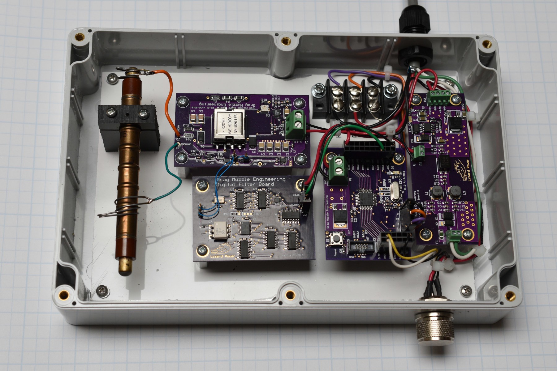
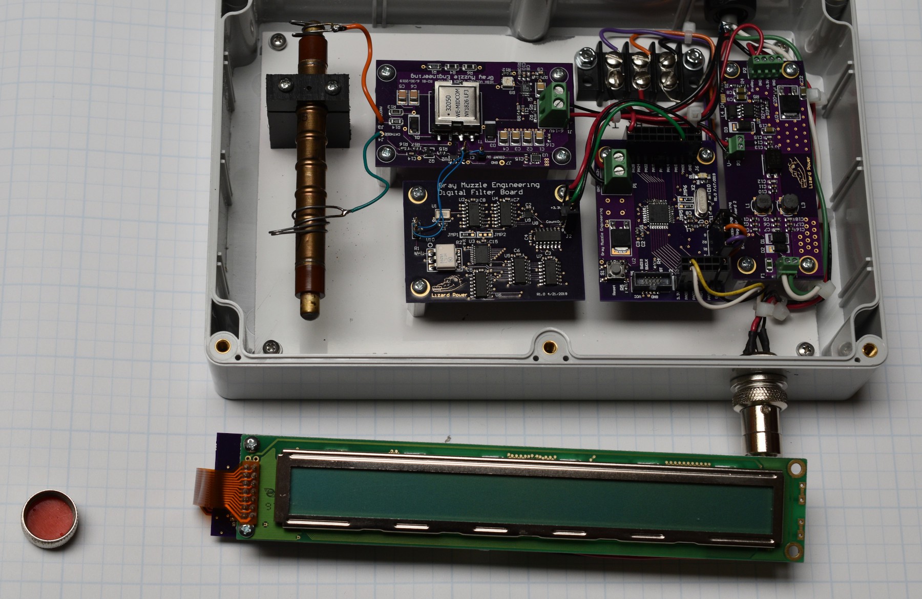
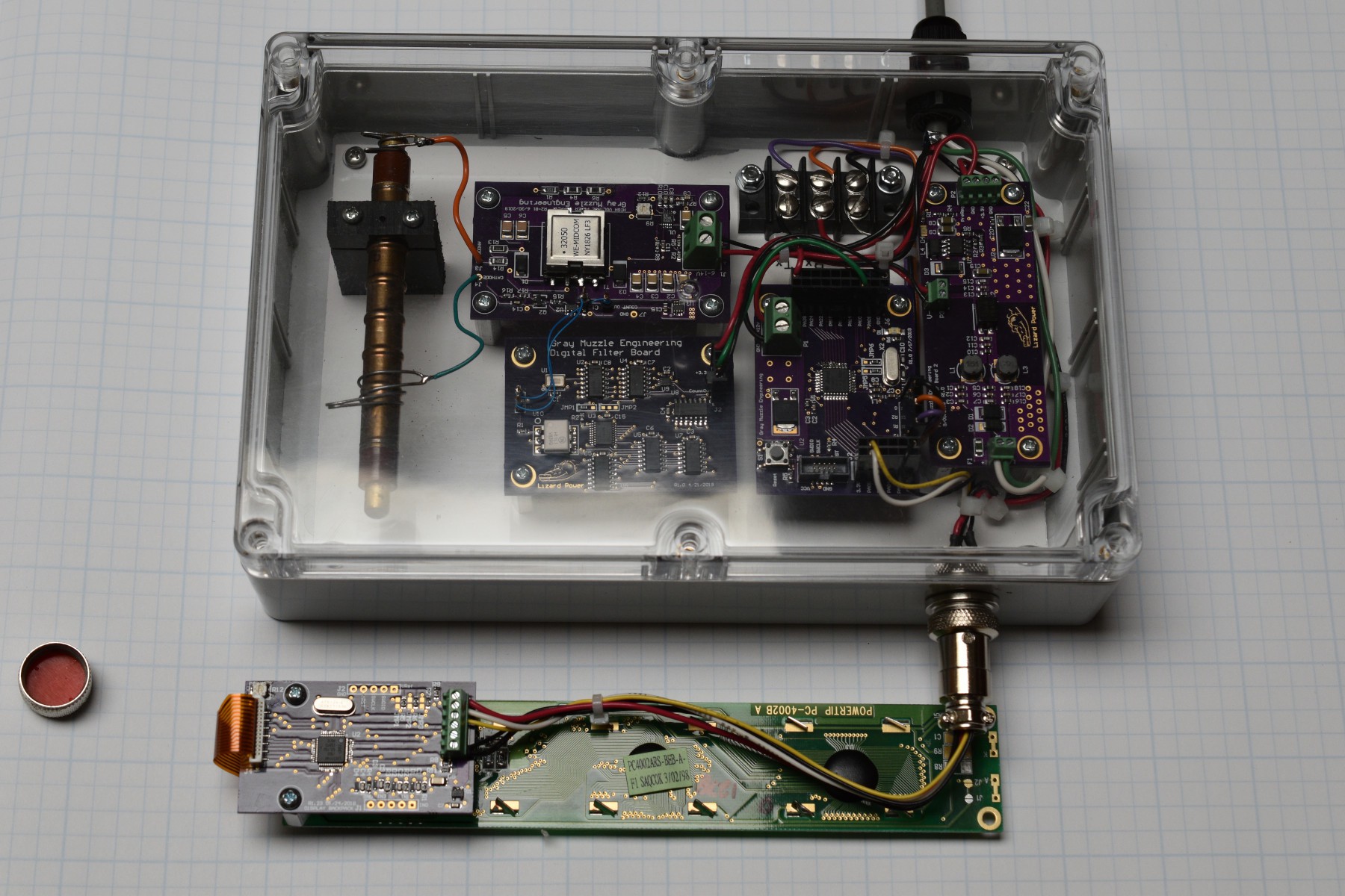
As you can see from the picture of the testbench for this project, it is buillt in several smaller blocks. I have been building small circuits for a while, as a chance to play with them and learn about better PCB layout techniques. This also results in having small building blocks to create larger projects from. This method also works well for incorporating manufacturers eval boards into a project. Because this project uses high enough voltage to destroy digital boards and tools, I put all of the boards on a metal breadboard setup to keep them from floating around and shorting together. Since this project is designed to go into a fixed location data acquisition system, there is no reason to build all the modules on a single PCB, so it will stay in this format. The completed system configuration will go into a weatherproof polycarbonate box, and the metal baseplate to mount all of the boards to is fabricated.
The modules used are:
1) HV Power supply and Geiger Mueller tube analog stuff.
2) Low pass digital filter.
3) MCU Board.
4) LCD Display and serial backpack.
5) Incoming power filter and pre-regulator board.
6) RS422 driver. May or may not incorporate.
All of the purple (OSHPark) boards in the picture are previous or current projects. Schematics for all of these boards are in the files section.
The Power Supply was the first block built for this project. I wanted a (sort of) high voltage power supply that I could use for other stuff like playing with Nixie tubes or EL wire in addition to this Geiger counter project. I picked the Linear Tech LT3757 chip, running in flyback mode. The output voltage from this circuit is adjustable from about 150VDC to about 425VDC. I have played with driving Nixie tubes with this supply, and it works well in this role.
My first iteration of the power supply board was very close to the LT data sheet design for the LT3757, including the RC snubber on the switch node. Messing with this circuit showed that the snubber was dissipating a noticeable amount of power and had problems with both the resistor and the cap surviving. Replacing the RC snubber with a diode snubber resulted in a much cleaner supply with lower power consumption and less smoke problems.
The Geiger Mueller tube is a metal sleeve (cathode) with a wire (anode) down the center, and it is filled with low pressure gas. When no radiation is being detected, the tube looks like an open circuit from the sleeve to the wire. When a particle of ionizing radiation passes into the tube (through the sleeve side), the gas ionizes and the tube conducts current from the sleeve to the wire. As long as the voltage across the tube is below the "self avalanche" level, the tube will stop conducting after about 30uS. This is an extremely hand-wavey explanation, if you want a better one, see Wikipedia: https://en.wikipedia.org/wiki/Geiger%E2%80%93M%C3%BCller_tube .
There is a 4.5M resistor between the HV power supply output + and the anode of the tube. A voltage divider between the tube cathode and ground gives an output signal to drive the base of a grounded emitter NPN transistor. The collector of the transistor is pulled up to 3.3V through a 4.7K resistor to give a 0 - 3.3V output signal from the tube. This signal is cleaned up with a Schmidt trigger inverter to give a well behaved logic signal output. One of the things that this project highlighted to me is that resistors have a voltage rating as well as a resistance value. Exceeding that voltage rating will cause bad things to happen!
I went through several iterations of PCB layout to get the flyback converter HV output as clean as possible. There are still some high frequency noise that shows up in the output. A simple 1 bit, digital low pass filter was implemented to clean this up. I though about trying to do this in the MCU software, but opted for the hardware approach.
The digital filter is a simple 8 bit shift register followed by some logic and a...
Read more » Bharbour



 Aleksa
 Cliffweb03
images seem to be broken (thanks, HaD) so I can't really see what the HV inverter looks like. Anyway, I built a radiation detector that ran continuously on 3 AA cells for > 1 1/2 years using a CCFL inverter transformer, along with a TS555 as comparator with hysteresis. Schematics: https://twitter.com/MisterHW/status/1321177043548209152