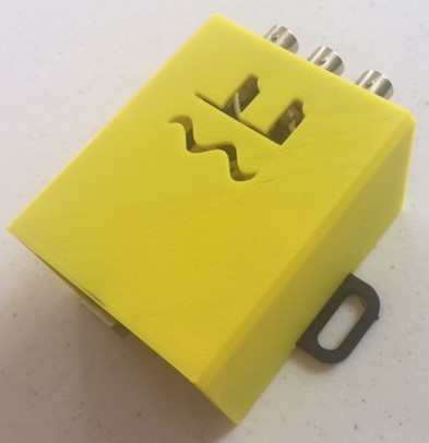
3D print the base and lid of the enclosure using the .stl files from the SignalBuddy github repo. The unit of the parts is inches.
2
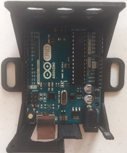
mount Arduino
The Arduino can snap into the base as shown here.
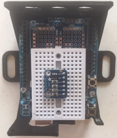
Now snap the prototyping shield (like this one, or similar) into the Arduino, and insert the MCP4725 into the breadboard.
3
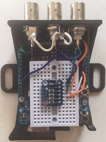
add BNC jacks and wire everything up!
Mount the BNC jacks into the side panel. Solder wires connecting the ground terminals of the BNC jacks to each other, and another connecting them to the ground on the shield. The gold pin on the 3 BNC jacks should be connected to Pin 2 (this is the external trigger input), VOUT of the MCP4725 (this is the analog output), and Pin 11 (this is the digital / PWM output).
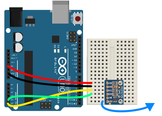
On the MCP4725, connect GND to ground, VDD to 5V, SCL to A5 on the shield, and SDA to A4 on the shield, like this:
4
add (optional) goodies
If you want to make SignalBuddy truly happy, you can add the following bells / whistles:
Tap the 4 holes in the base for M2.5 screws to screw-mount the Arduino.
Tap the 4 holes in the inner brackets of the lid so the box can be securely closed with M2.5 screws.
Add a button to the cutout near the USB jack. Wire it such that pressing it causes the trigger pin to go high, making SignalBuddy deliver signals with the push of a button.
Add LEDs to the holes beneath the BNC jacks. Splitting the PWM output of analog output to a pair of LEDs will cause them to light up as signals are delivered to external devices.
5
upload code
Download the code and follow the instructions on the SignalBuddy github repo to generate your signals!
Discussions
Become a Hackaday.io Member
Create an account to leave a comment. Already have an account? Log In.