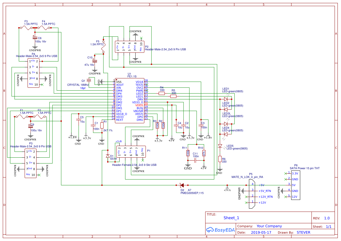
Looking around online I found several schematics that were close to what I wanted but no cigar. The hub needed to plug onto an internal USB header with optional power to it, with a pass through of the unused port of the header. The hub needed to have pins rather than sockets to suit accessories intended for internal connection.
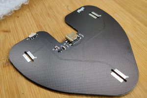
I messed up the mk1 pcb by missing 3 components, these were bodge wired on to get it working, the other issue was that it obstructed the 2nd motherboard USB header requiring a move.
The hub chips do not monitor the actual current as when powered it is external to them so I included PPTC fuses on the power outputs, equally when unpowered 100uf caps are there just in case. Due to headers not having the same spacing as sockets it is only necessary to have one cap per header :)
I am uploading just the schematic as that is working, ( the MK umpteen pcb's are in the post ), actually 2 versions, one with the motherboard connection central and the other offset.
The PWR suffix on the schematic is used in the design rules for auto routing with a track width of 1 or 2mm, non PWR tracks are .3mm wide, the latest pcb is manually routed and far more tidy than the early auto routed version.
Track impedance of the differential pairs (90 ohms for usb2) was done using https://www.eeweb.com/tools/edge-coupled-stripline-impedance
 electronicsworkshops
 Wim Van Gool