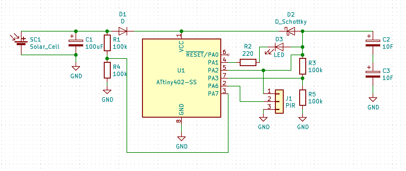
How about this?
- The solar PV charges C1 to whatever it can manage. If it's above 1.8V + Vf of D1, the ATtiny turns on and measures that voltage between R1 and R4.
- Then it measures R3-R5 . If the solar cell - Vf for D1 is higher than the voltage across C2-C3, the ATtiny turns PA2 OUTPUT HIGH (maybe PWM) and, turning the resistor divider on again, waits until C1 drops to a given value or by a given amount.
- Then it turns PA2 to INPUT and notes the timestamp. It waits until C1 voltage recovers by a certain amount or to a certain level and then compares the time to the timestamp. From doing this at a few voltage ranges/drops, it may be possible to approximate an MPP for the solar cell.
- I should explain the LED and the PIR connector. The LED will be a night light, so PA1 will be kept as an INPUT until the LED is needed, when PA1 will be turned to OUTPUT LOW. The PIR sensor is monitored, perhaps with an interrupt or just polling. When R1-R4 indicates the solar panel is not able to generate, the ATtiny will assume the room is dark and any PIR trigger on PA6 will result in it turning the LED on.
 Simon Merrett
Discussions
Become a Hackaday.io Member
Create an account to leave a comment. Already have an account? Log In.
Cool!
- Assuming this is indoors, you will likely need a boost converter to maximize power from the solar cell. THis could be implemented as a switch and inductor, switch driven by U1. Will allow you to draw power from the solar cell even when its output voltage is below 1.8V.
- Leakage from 100K resistors are likely to be large contributors if the device is on infrequently. You may want to change R1/R4, R3/R5 to >1M to minimize leakage
- Consider a resistor on the PA2 output to limit max current draw into the caps
Are you sure? yes | no