0%
0%
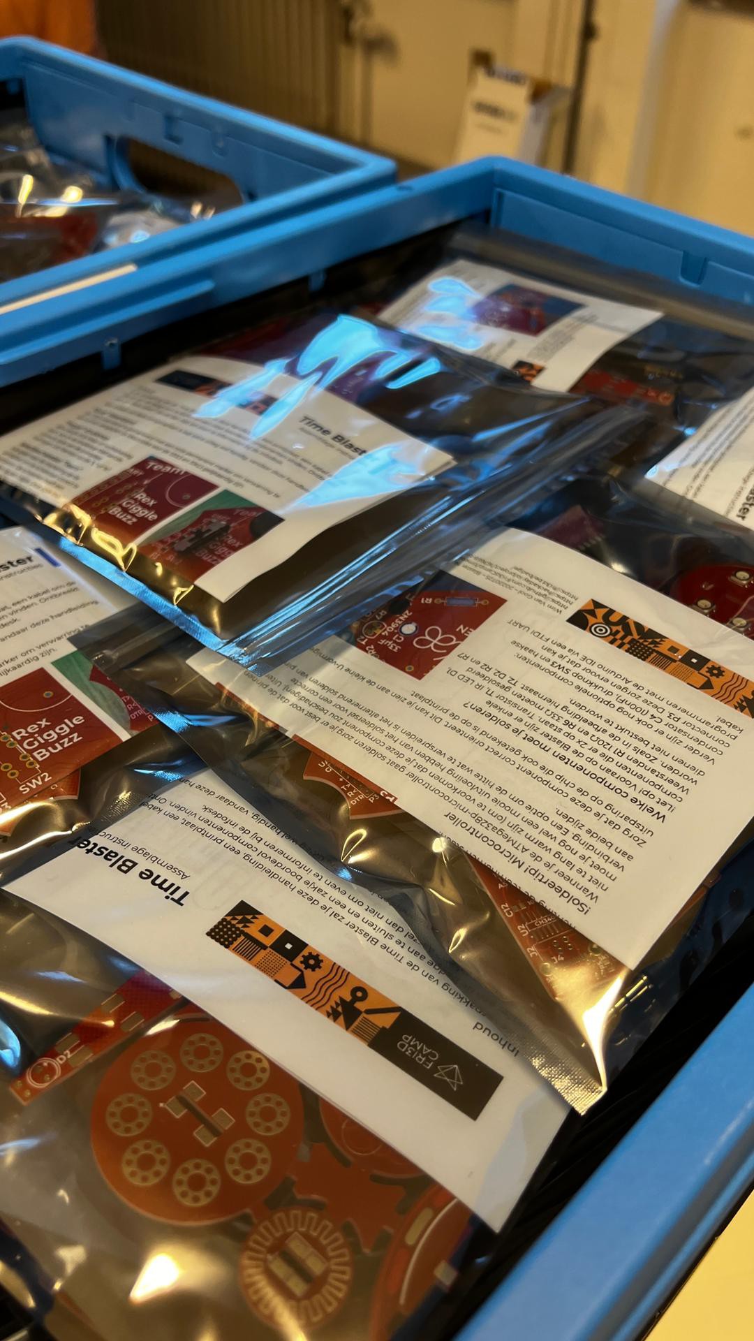
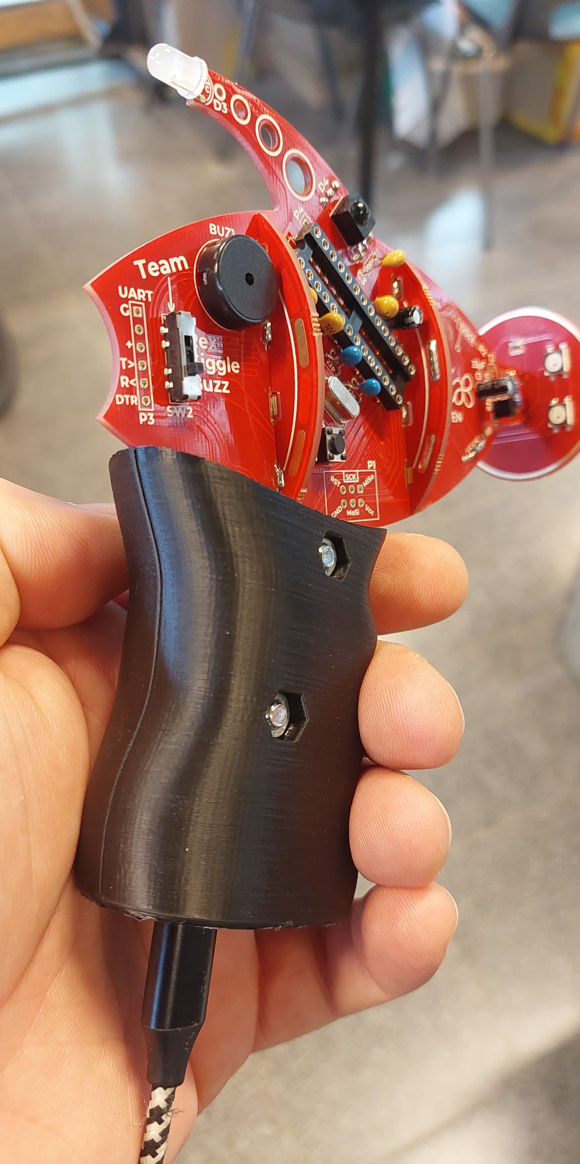
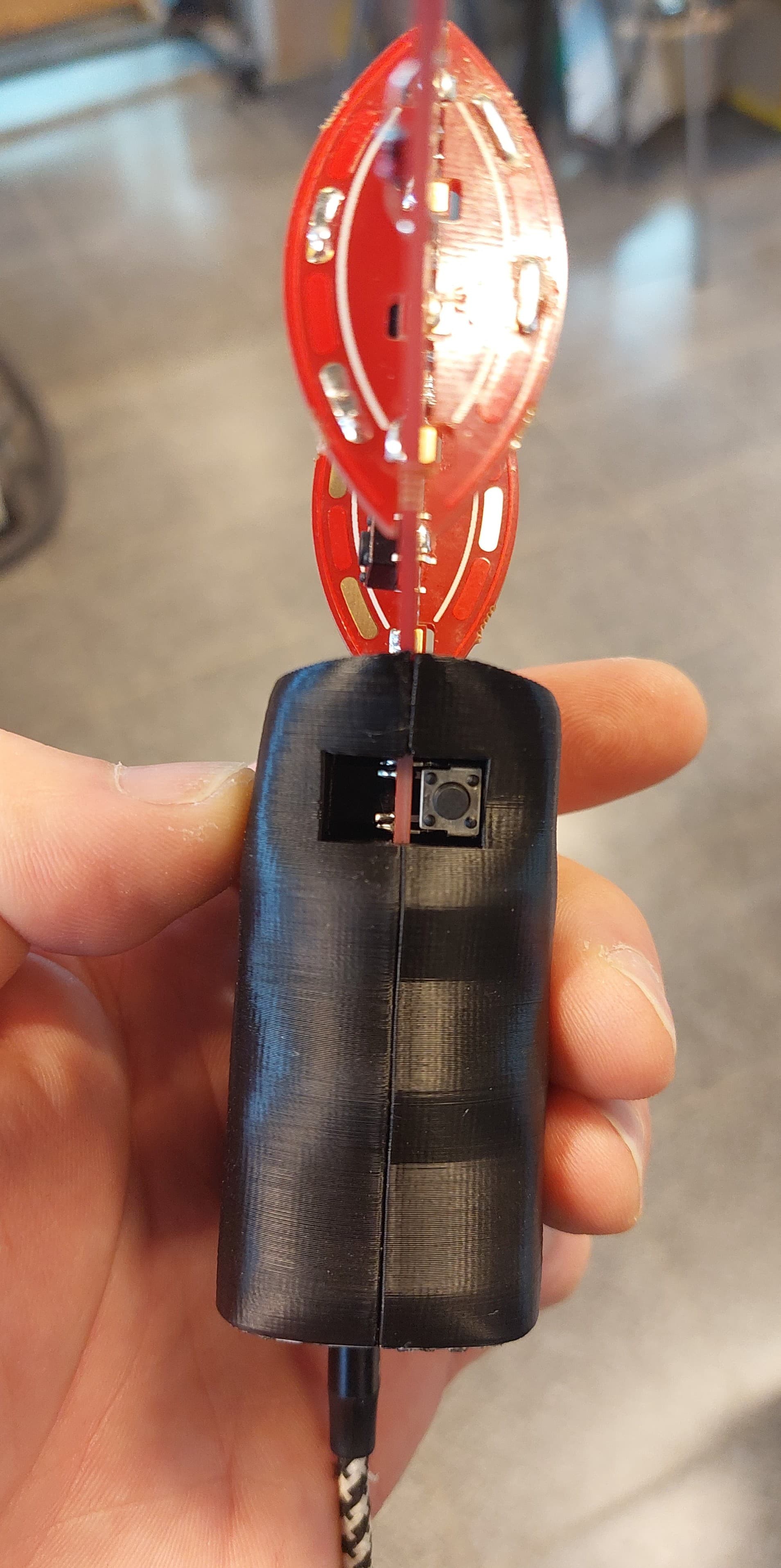
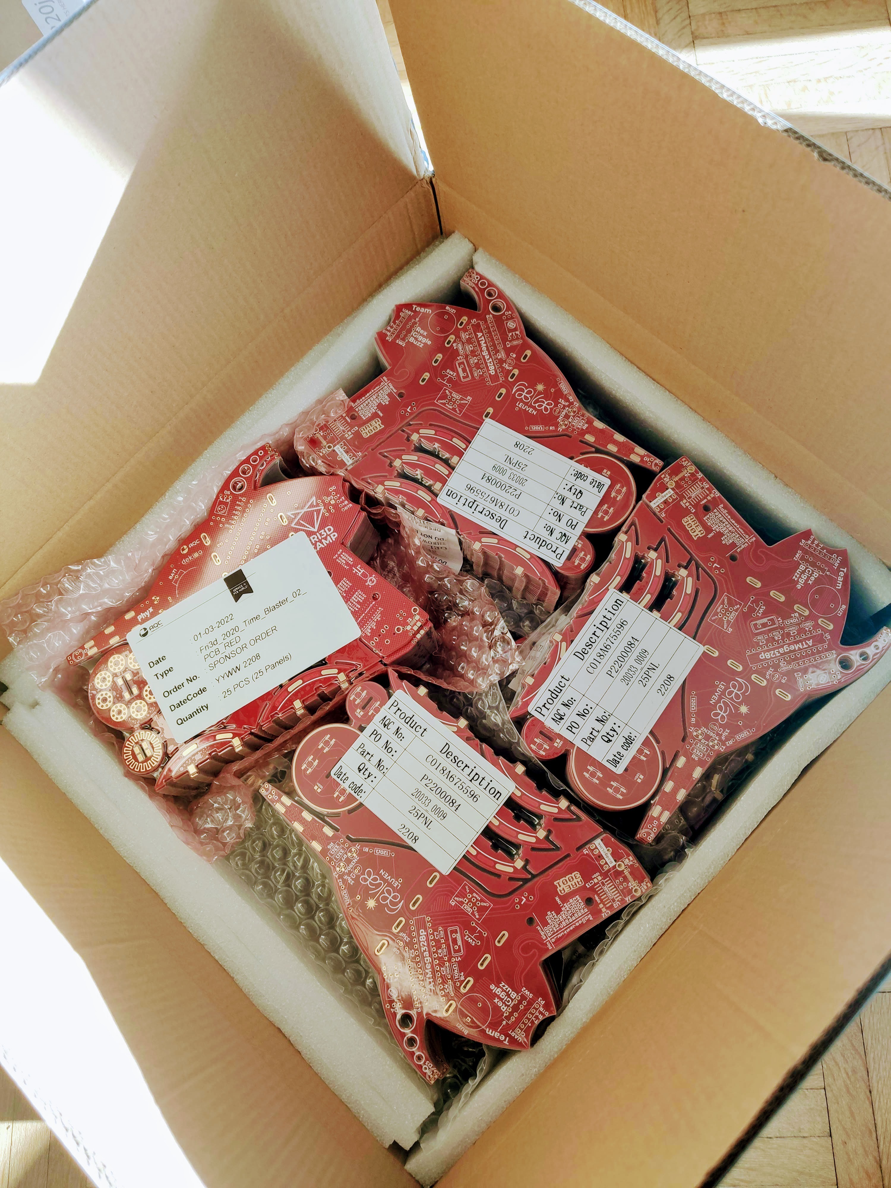
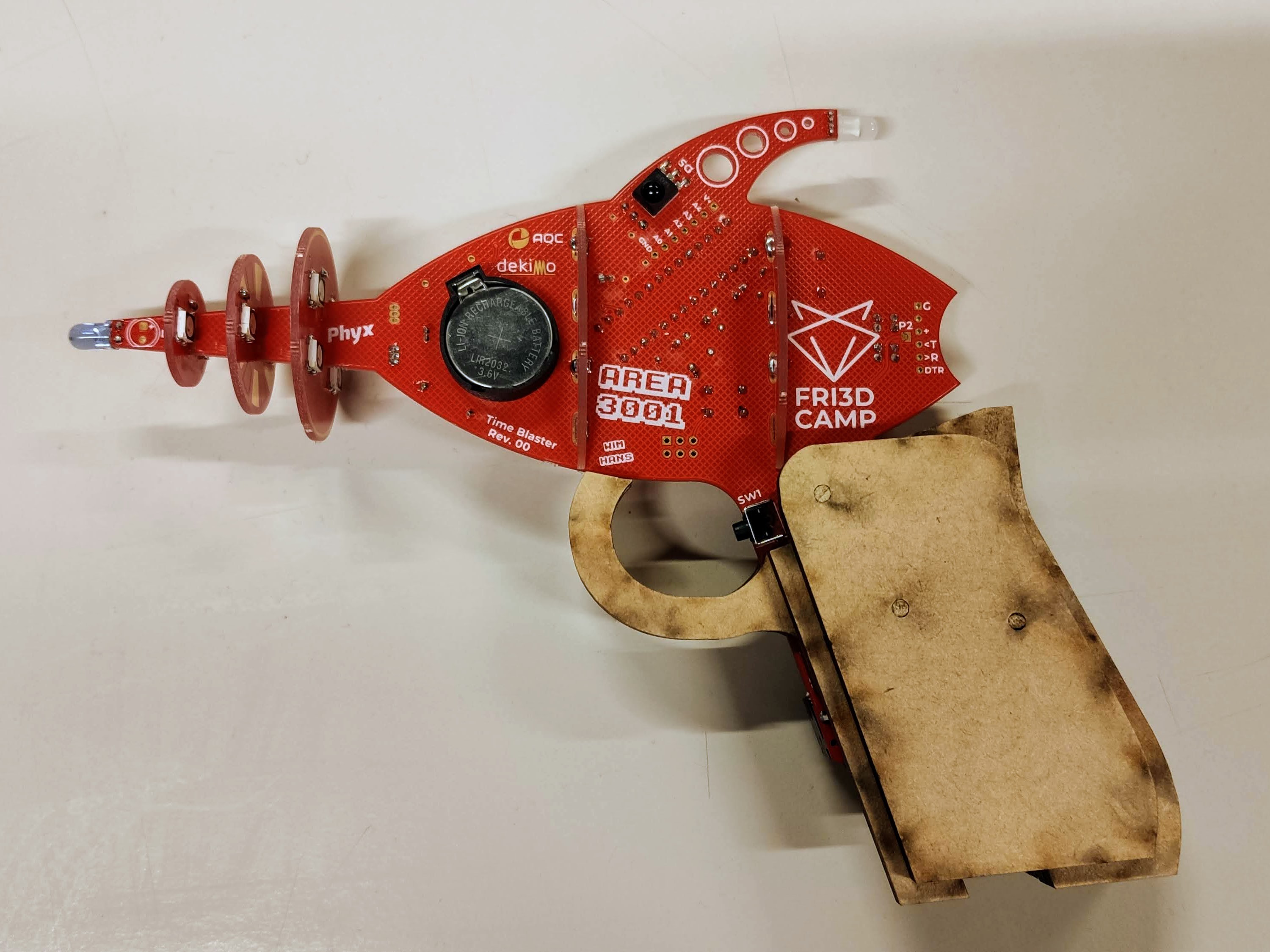
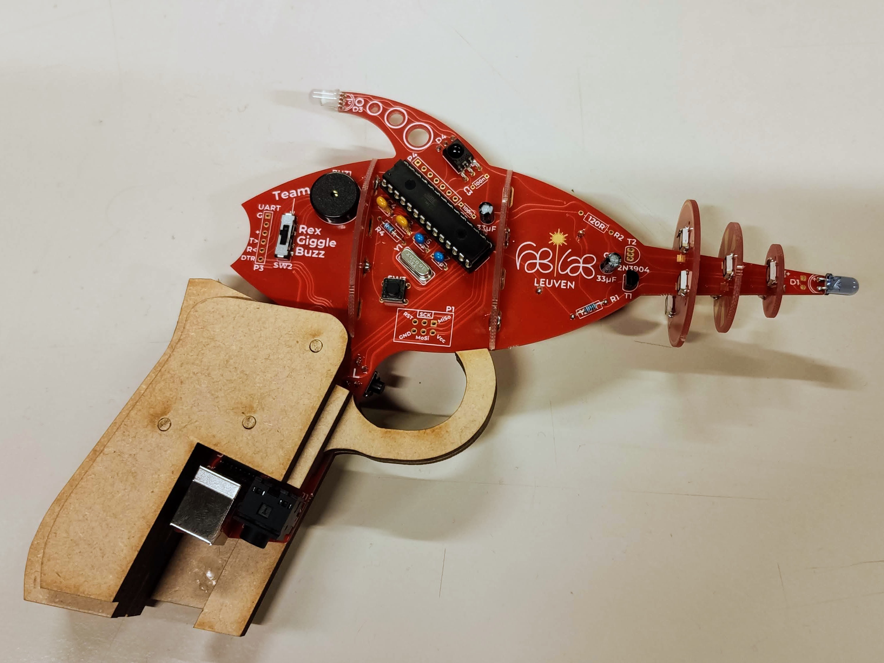
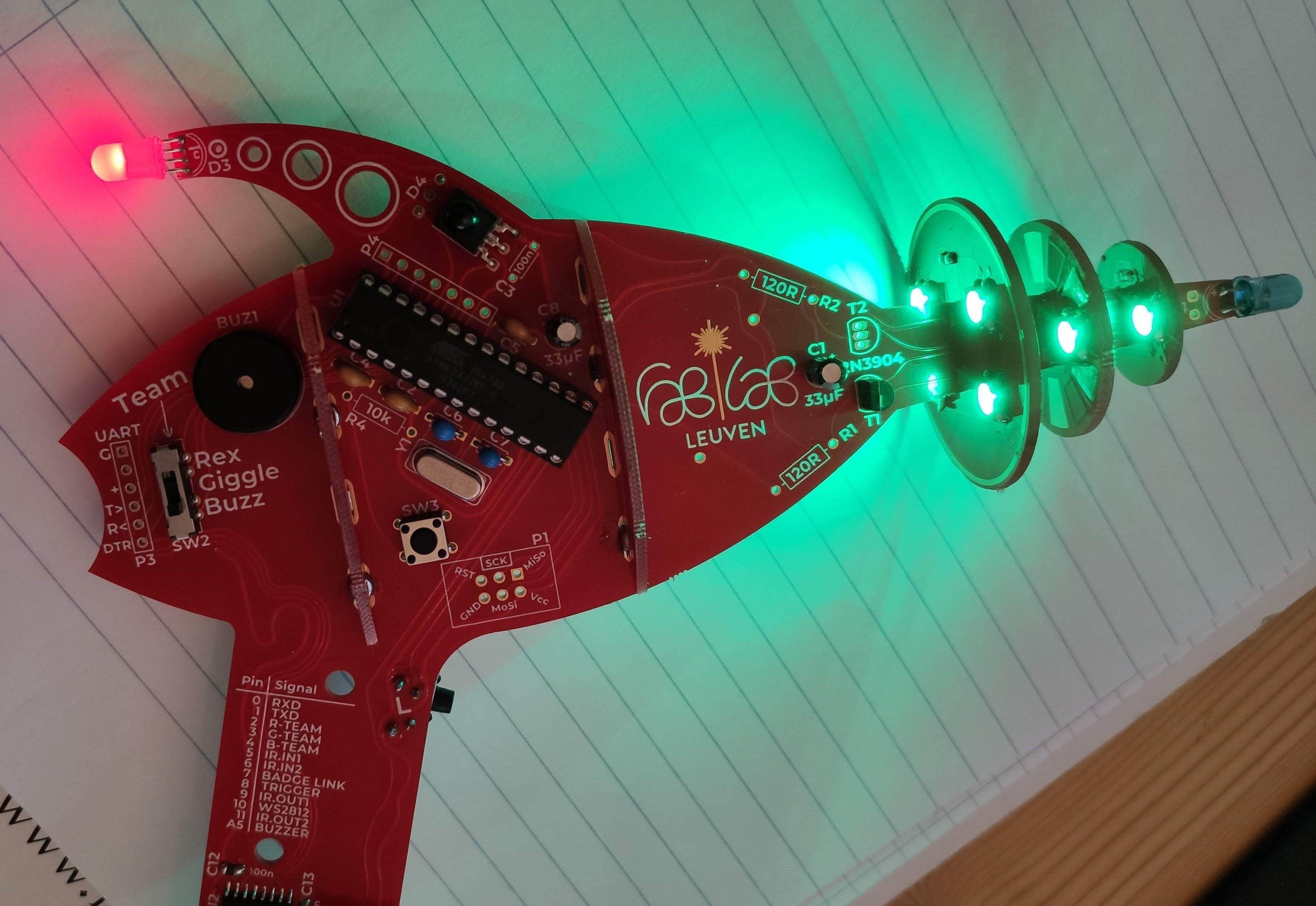
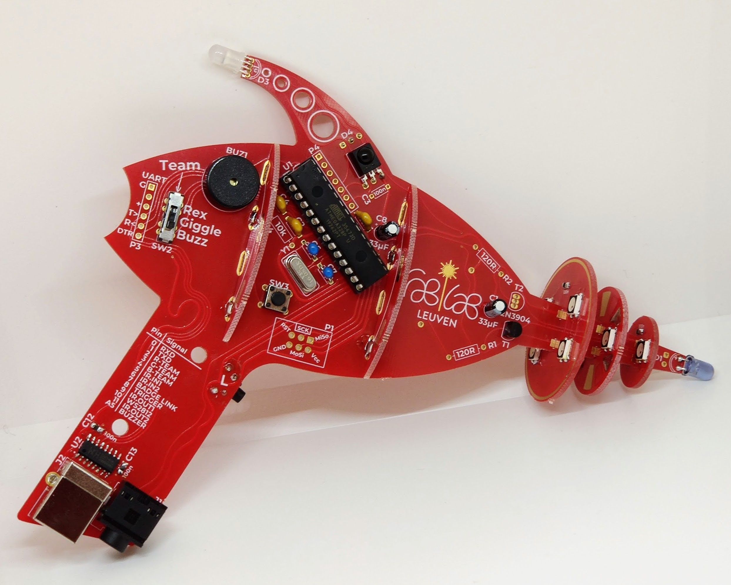
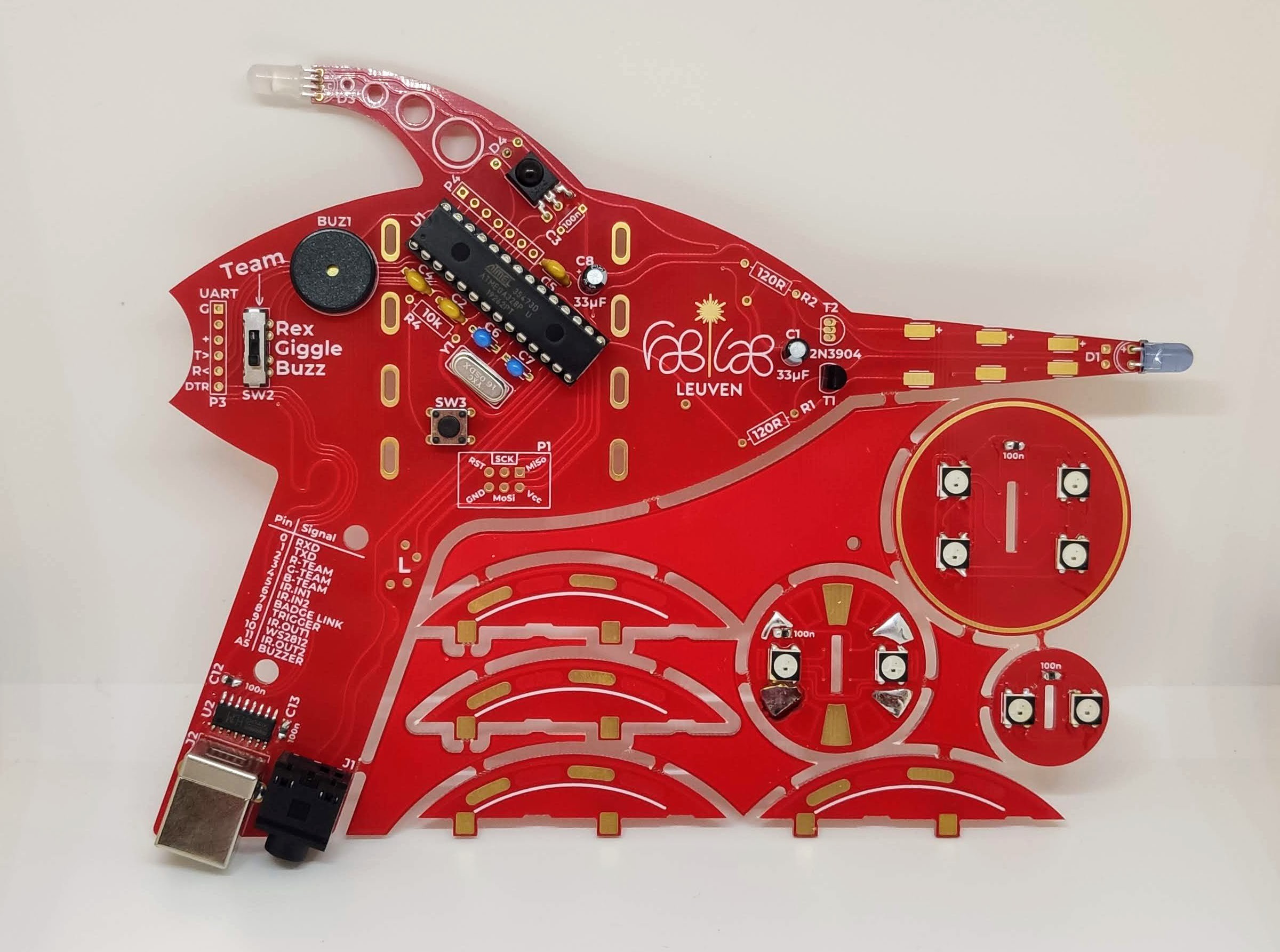
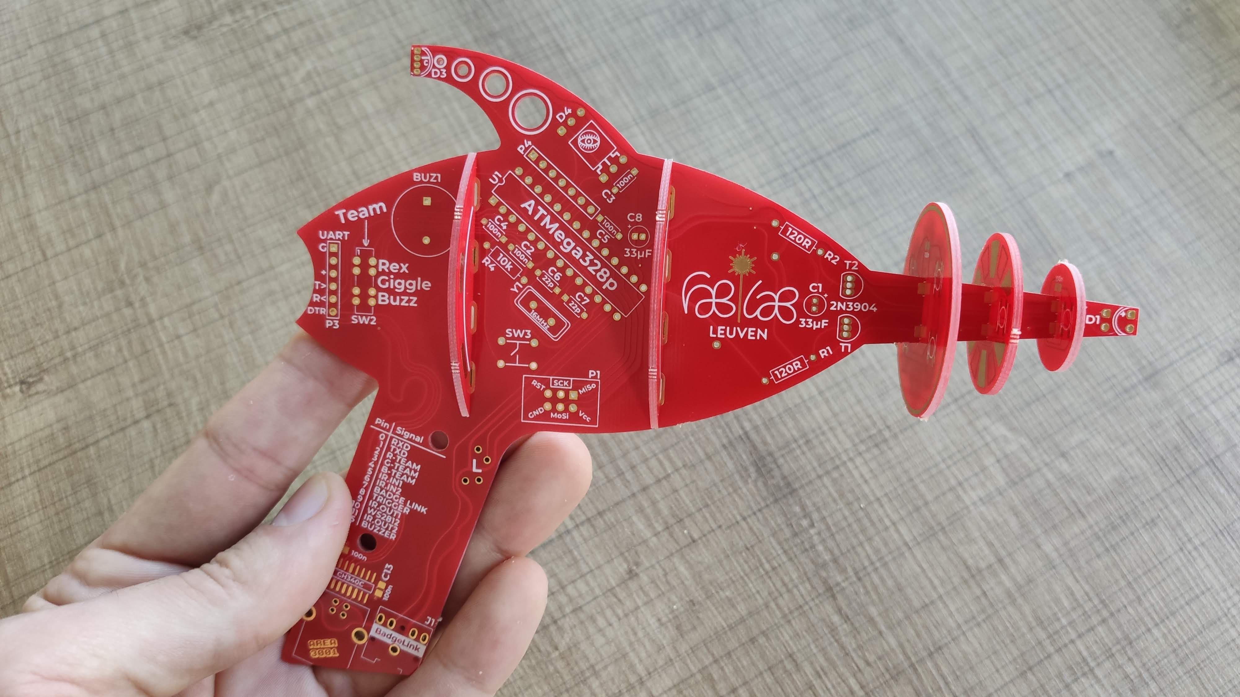
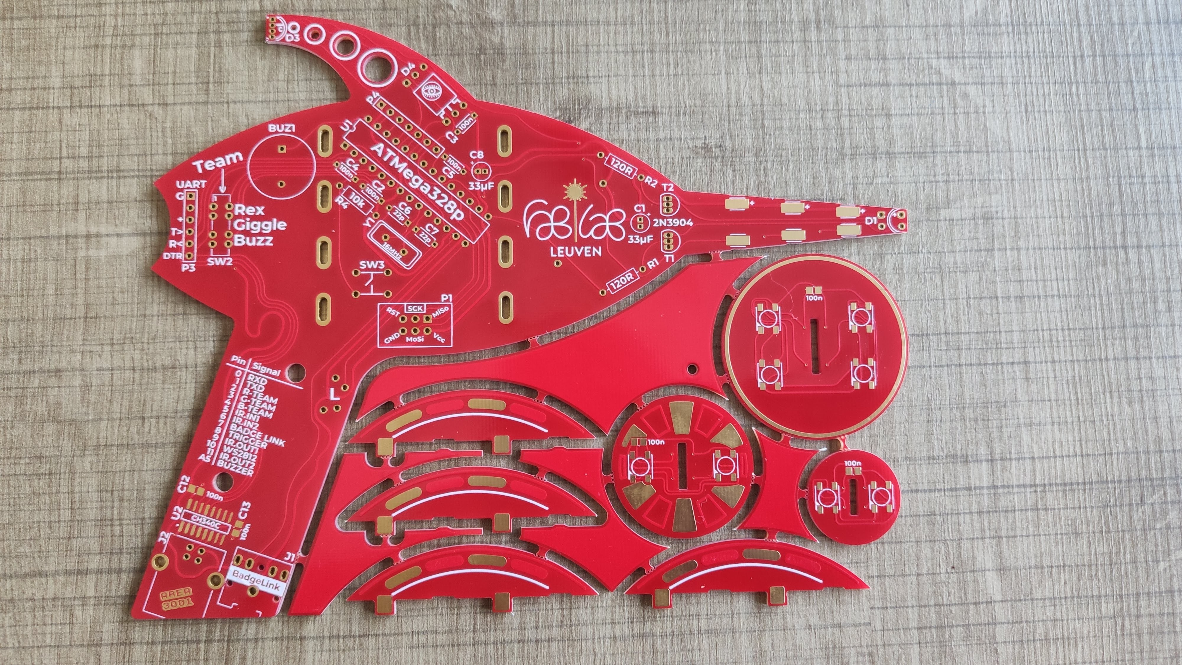
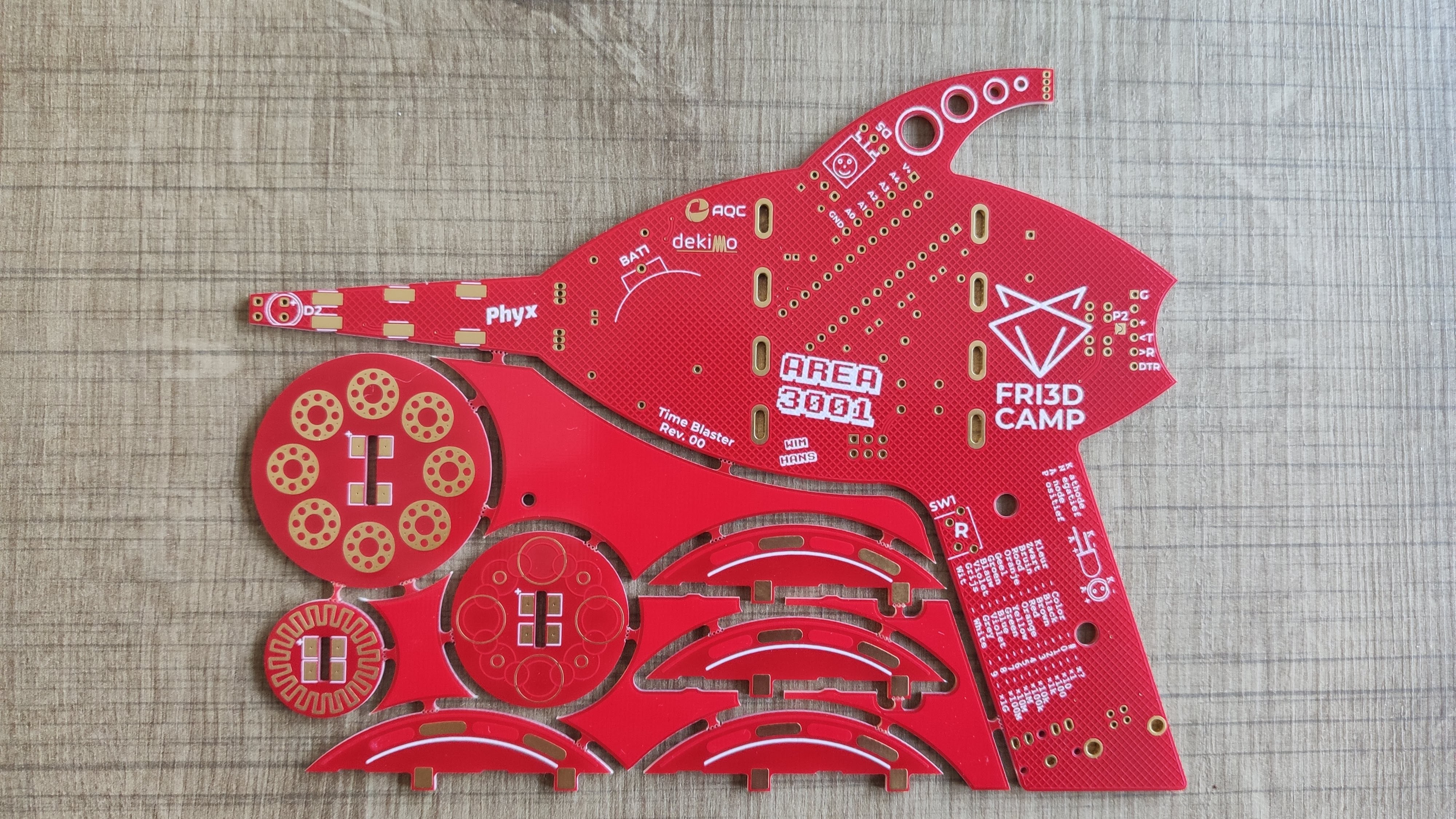
Time Blaster
IR blaster to be used with the Fri3dcamp 2020 badge
 Wim Van Gool
Become a Hackaday.io member
Already have an account? Log in.
Just one more thing
To make the experience fit your profile, pick a username and tell us what interests you.
Pick an awesome username
hackaday.io/
Your profile's URL: hackaday.io/username. Max 25 alphanumeric characters.
Pick a few interests
Projects that share your interests
People that share your interests


 Paul Stoffregen
 Stephen Holdaway
 Sam Ettinger
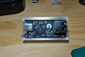
 Thomas Bladykas
hi. not clear to me which is the receiver